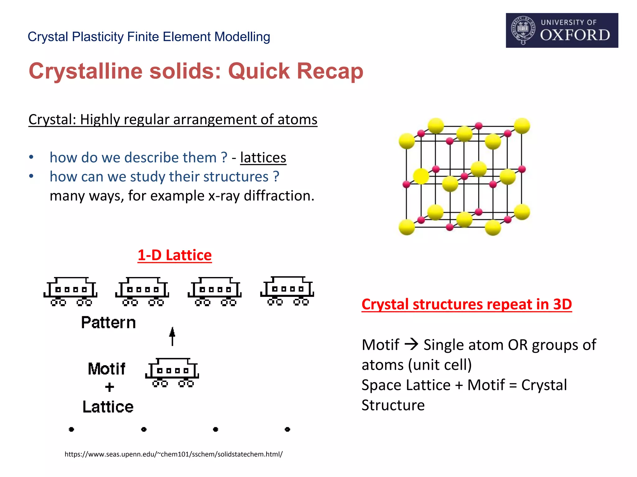
This document provides an overview of crystal plasticity finite element modelling (CPFE). It begins with a recap of important concepts in crystal plasticity including crystalline structures, plasticity occurring through dislocation glide, slip systems, and factors like Schmid factor and critically resolved shear stress that determine when slip occurs. It then discusses why CPFE is needed to model plastic deformation at the crystal level since continuum models do not consider dislocation slip. The key aspects CPFE aims to model are then outlined, including resolving loads onto slip systems, calculating slip and resulting strains, lattice rotation, and dislocation density evolution. Constitutive laws for calculating slip rates are also briefly introduced.


![Crystal Plasticity Finite Element Modelling
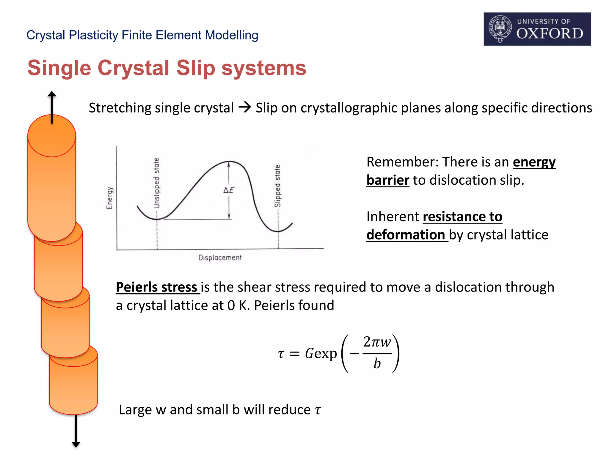
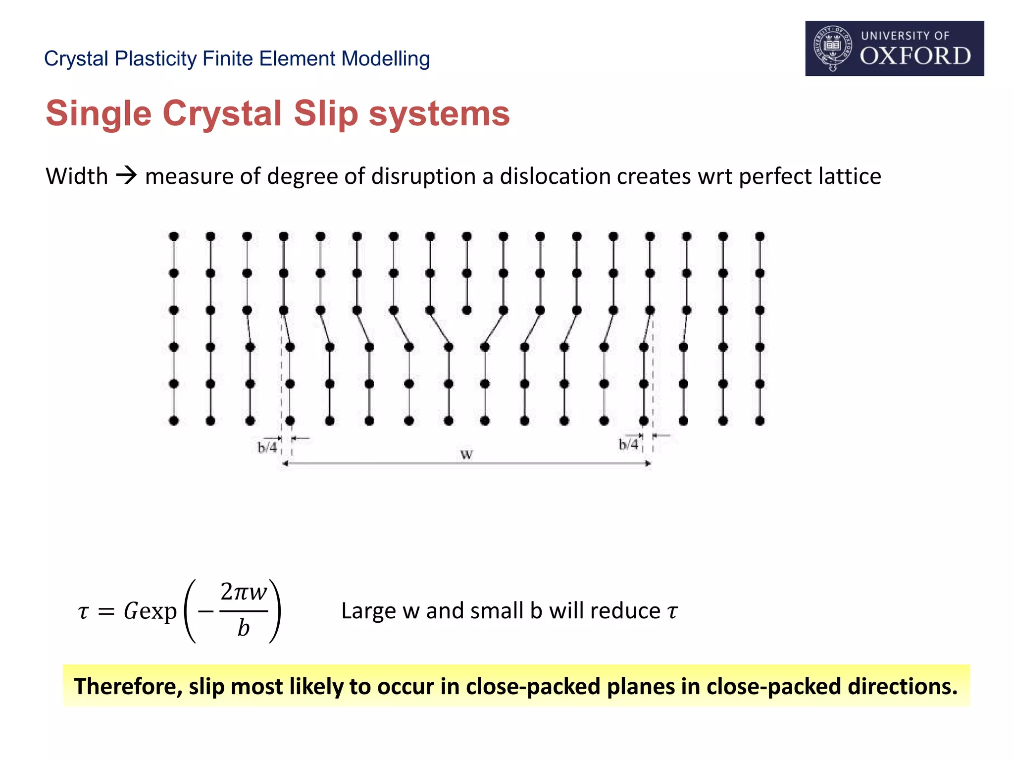
Single Crystal Slip systems
Stretching single crystal Slip on crystallographic planes along specific directions
Slip Directions: Shortest Lattice repeat vectors
Slip Planes: Planes with highest in-plane density
Stretching single crystal Slip on crystallographic planes along specific directions
X
Y
Z
(111)
½[𝟏ഥ𝟏 𝟎]
FCC
Z
X
Y
(110)
½[ഥ𝟏𝟏𝟏]
BCC
Q. How many slip systems in BCC & FCC?](https://image.slidesharecdn.com/cpfelecturesdasnov2018-190527221150/75/Introduction-to-Crystal-Plasticity-Modelling-21-2048.jpg)


![Crystal Plasticity Finite Element Modelling
Y
ZX
[100]
[110]
[1-10]
5 µm
5 µm
• Substantial Increase in Pile Up
• Slip localization
• Higher max load
0
30
60
90
0 200 400 600
LoadonElement(mN)
Depth (nm)
Load vs Depth
Implanted
Unimplanted
Nano-Indentation SEM
[010]
4.2 µm radius; 500 nm deep
Unimp
He-imp
S. Das et al., Scr. Mater. 146 (2018) 335–339.
http://linkinghub.elsevier.com/retrieve/pii/S1359646217307145](https://image.slidesharecdn.com/cpfelecturesdasnov2018-190527221150/75/Introduction-to-Crystal-Plasticity-Modelling-65-2048.jpg)


