Downloaded 345 times
![Example on fluctuating stressExample on fluctuating stress
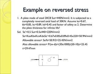
1. A circular rod made of ductile material has endurance strength of
280N/mm2 and ultimate strength of 350N/mm2. The member is
subjected to variable axial load varying from 300KN(tensile) and
70KN(compressive). Assume Ka=0.85, Kb=1.0, Kc=1,Kd=0.55 and
factor of safety as 2. Find suitable diameter of the rod?
Sol. Se’=280N/mm2
Sut=350N/mm2
Using Goodman line equation:
Sm/Sut + Sa/Se=1/fs……………………(1)
Se=KaxKbxKcxKcxKdxSe’=0.85x1x1x0.55x280=132.3MPa
Sm=(Pmax+Pmin)/2A=[300+(-70)]/2A=115/A N/mm2
Sa=(Pmax-Pmin)/2A=[300-(-70)]/2A=185/A N/mm2
Put values in eqn. 1 we get: A= 3456mm2
Now A= π/4 d2=3456 or d=66.3mm](https://image.slidesharecdn.com/metalfatigueppt-170113123938/85/Metal-fatigue-ppt-22-320.jpg)


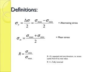
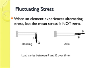
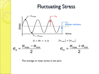
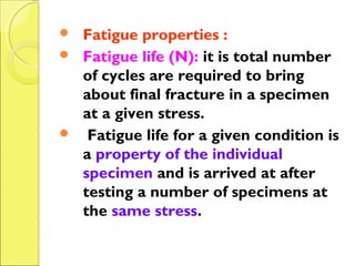
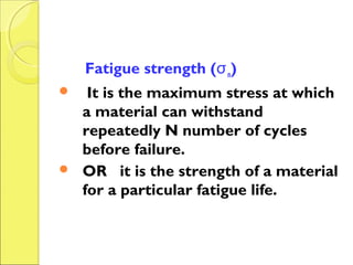
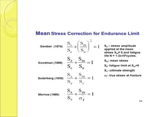
The document discusses the effects of fluctuating stresses on material fatigue in mechanical design, highlighting the differences between cyclic loading and mean stresses. It defines key concepts such as fatigue life, fatigue strength, and endurance limit, providing formulas for calculating these parameters in design applications. Examples illustrate how to determine component dimensions based on fluctuating stress conditions and material properties.


