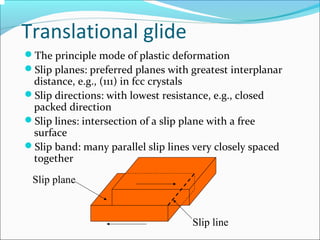
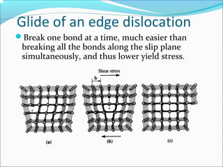
S. N. PATEL INSTITUTE OF TECHNOLOGY
&
RESEARCH CENTRE
Vidyabharti Campus, Umrakh, Bardoli, Surat –
394345.
BRANCH : M.E.(PRODUCTION ENGINEERING)
SUBJECT :ADVANCE MATERIAL TECHNOLOGY
“ PLASTIC DEFORMATION
”
GUIDED BY:
MISAL GANDHI
SIR
PREPARED BY:
KAUSHIK
SONAGARA
PEN NUMBER :
170490728018
CONTENTS…
- PLASTIC DEFORMATION
- DEFRCT
- EDGE/ SCREW DISLOCATIONS
- STRENGTHENING MECHANISMS
- POLYCRYSTALLINE MATERIALS
- PLASTIC DEFORMATION IN POLYCRYSTALS
- LITERATURE REVIEW
- CONCLUSION
- REFRENCES
Plastic deformation
Material remains intact
Original crystal structure is not destroyed
Crystal distortion is extremely localized
Possible mechanisms:
Translational glide (slipping)
Twin glide (twinning)
Translational glide
The principle mode of plastic deformation
Slip planes: preferred planes with greatest interplanar
distance, e.g., (111) in fcc crystals
Slip directions: with lowest resistance, e.g., closed
packed direction
Slip lines: intersection of a slip plane with a free
surface
Slip band: many parallel slip lines very closely spaced
together
Slip plane
Slip line
Existence of defects
Theoretical yield strength predicted for perfect
crystals is much greater than the measured
strength.
The large discrepancy puzzled many scientists
until Orowan, Polanyi, and Taylor (1934).
The existence of defects (specifically,
dislocations) explains the discrepancy.
Defects
Point defects: vacancies, interstitial atoms,
substitional atoms, etc.
Line defects: dislocations (edge, screw, mixed)
Most important for plastic deformation
Surface defects: grain boundaries, phase
boundaries, free surfaces, etc.
Edge dislocations
Burgers vector: characterizes the “strength” of dislocations
Edge dislocations: b ⊥ dislocation line
Screw dislocations
Burgers vector b // dislocation line
Mixed dislocation
Have both edge and screw components.
Observation of dislocations
Transmission Electron microscopy (TEM): diffraction
images of dislocations appear as dark lines.
Glide of an edge dislocation
Break one bond at a time, much easier than
breaking all the bonds along the slip plane
simultaneously, and thus lower yield stress.
Motion of dislocations
Force acting on dislocations
Applied shear stress (τ) exerts a force on a dislocation
Motion of dislocation is resisted by a frictional force (f,
per unit length)
Work done by the shear stress (Wτ) equals the work
done by the frictional force (Wf).
( ) bllW ×= 21ττ
( ) 21 lflWf ×=
bfWW f ττ =⇒=
Lattice friction stress
Theoretical shear strength:
Lattice friction stress for dislocation motion:
Lattice friction stress is much less than the theoretical
shear strength
Dislocation motion most likely occurs on closed packed
planes (large a, interplanar spacing) in closed packed
directions (small b, in-plane atomic spacing).
π
τ
2
max
G
=






−==
b
a
G
b
f
f
π
τ
2
exp
Interactions of dislocations
Two dislocations may repel or attract each
other, depending on their directions.
Repulsion Attraction
Line tension of a dislocation
Atoms near the core of a dislocation have a higher
energy due to distortion.
Dislocation line tends to shorten to minimize energy,
as if it had a line tension.
Line tension = strain energy per unit length
T
T
2
2
1
GbT ≈
Dislocation bowing
Dislocations may be pinned by solutes, interstitials,
and precipitates
Pinned dislocations can bow when subjected to shear
stress, analogous to the bowing of a string.
τbL
T T
θ
R
θ/2θ/2
bLT τ
θ
=





2
sin2
τ2
Gb
R =
2
2
1
GbT ≈
R
L
Dislocation multiplication
Some dislocations form during the process of crystallization.
More dislocations are created during plastic deformation.
Frank-Read Sources: a dislocation breeding mechanism.
Frank-Read sources in Si
Strengthening mechanisms
Pure metals have low resistance to dislocation
motion, thus low yield strength.
Increase the resistance by strengthening:
Solution strengthening
Precipitate strengthening
Work hardening
Solution strengthening
Add impurities to form solid solution (alloy)
Example: add Zn in Cu to form brass, strength
increased by up to 10 times.
Cu Cu Cu Cu Cu Cu
Cu Cu Cu
Cu Cu Cu Cu
Zn Zn
Bigger Zn atoms make the
slip plane “rougher”, thus
increase the resistance to
dislocation motion.
Precipitate strengthening
Precipitates (small particles) can promote
strengthening by impeding dislocation motion.
Dislocation bowing and looping.
Critical condition at semicircular
configuration:
TbL 2=τ
L
Gb
bL
T
≈=
2
τ
Work-hardening
Dislocations interact and obstruct each other.
Accounts for higher strength of cold rolled steels.
σ
ε
σYU
σYL
Strain hardening
×
σUTS
εf
Polycrystalline materials
Different crystal orientations in different grains.
Crystal structure is disturbed at grain boundaries.
Plastic deformation in polycrystals
Slip in each grain is constrained
Dislocations pile up at grain boundaries
Gross yield-strength is higher than single crystals
(Taylor factor)
Strength depends on grain size (Hall-Petch).
YY τσ 3=
2/1
0
−
+= KdY σσ
Dislocation pile-up at grain boundaries
Sr. No. Title Name of
Publication
Author Objective Conclusion
1 On the Mechanism of
Plastic
Deformation Induced
Surface
Roughness
ASME Y. Z. Dai,
F. P. Chiang
The plastic
deformation induced
solace roughening
mechanism of
aluminium sheets
is experimentally
investigated.
It should be
noted,
however, that
all the
specimens
used are
made of
aluminum
which is a fee
material
2 Plastic-deformation
mechanism in
complex solids
ARTICLES M. Heggen,
L. Houben ,
M.
Feuerbacher
In simple crystalline
materials, plastic
deformation mostly
takes place by the
movement of
dislocations.
The samples
were cut into
slices and
prepared for
transmission
electron
microscopy
by subsequent
grinding,
polishing and
argon-ion
milling.
LITERATURE REVIEW
Sr. No. Title Name of
Publication
Author Objective Conclusion
3 Plastic
Deformation
Mechanisms of
Semicrystalline
and Amorphous
Polymers
macroletters Sara Jabbari-
Farouji,Joerg
Rottler,Olivier
Lame,Ali Makke,∥
Michel Perez,and
Jean-Louis Barrat,
We use large-
scale molecular
dynamics
simulations
to investigate
plastic
deformation of
semicrystalline
polymers with
randomly
nucleated
crystallites.
simulations of
coarse-grained
semicrystalline
polymers allow us to
observe directly the
mechanisms of
plastic
deformation at
length scales smaller
than 100 nm which
are not
accessible by
experiments.
4 Mechanism of
plastic
deformation of
powder metallurgy
metal matrix
composites of
Cu–Sn/SiC and
6061/SiC under
compressive
stress
ELSEVIER Y.C. Lin,
H.C. Li,
S.S. Liou,
M.T. Shie
Under
compressive
stress, the plastic
deformation
mechanism of the
powder metallurgy
(P/M) process
metal matrix
composite (MMC)
varies with the
bonding strength
of interfaces.
Plastic deformation
of MMC under
compressive loading
proceeds by two
mechanisms “grain
deformation” and
“boundaries slip”—
according to the
bonding strength
among the different
powder particles.
Sr. no Title Name of
Publication
Author Objective Conclusion
5. Plastic
deformation
mechanism in
nanotwinned
metals: An
insight
from molecular
dynamics and
mechanistic
modeling
ELSEVIER Ting Zhua,
Huajian Gaob,
the deformation
mechanisms in
nanotwinned
copper, as
studied by
recent molecular
dynamics,
dislocation
mechanics and
crystal plasticity
modeling.
This
study should
involve various
combinations of
incoming
and outgoing
edge and screw
dislocations, as
well as the
competing
processes of
twinning and
detwinning that
are particularly
encouraged by
the large
number of
intersections
between TBs
and grain
boundaries.
CONCLUSION
If deformation is carried out at high temperatures above
the recrystallization temperature wherein, new strain free
grains are continuously forming as the deformation
proceeds, strain rate becomes the important parameter
instead of net strain.
REFRENCES
 We would like to thank the army research office, engineeringscience division for
financial support through contract no. Daa03-88-k-0033.
 T. Zhu, H. Gao / scripta materialia 66 (2012) 843–848
 We thank C. Thomas and M. Schmidt for producing the materials and J. Barthel for
carrying out the HAADF-STEM image simulation.
 S. Chung, B.H. Hwang, tribol. Int. 27 (1994) 307.
Thank you…

PLASTIC DEFORMATION

  • 1.
    S. N. PATELINSTITUTE OF TECHNOLOGY & RESEARCH CENTRE Vidyabharti Campus, Umrakh, Bardoli, Surat – 394345. BRANCH : M.E.(PRODUCTION ENGINEERING) SUBJECT :ADVANCE MATERIAL TECHNOLOGY “ PLASTIC DEFORMATION ” GUIDED BY: MISAL GANDHI SIR PREPARED BY: KAUSHIK SONAGARA PEN NUMBER : 170490728018
  • 2.
    CONTENTS… - PLASTIC DEFORMATION -DEFRCT - EDGE/ SCREW DISLOCATIONS - STRENGTHENING MECHANISMS - POLYCRYSTALLINE MATERIALS - PLASTIC DEFORMATION IN POLYCRYSTALS - LITERATURE REVIEW - CONCLUSION - REFRENCES
  • 3.
    Plastic deformation Material remainsintact Original crystal structure is not destroyed Crystal distortion is extremely localized Possible mechanisms: Translational glide (slipping) Twin glide (twinning)
  • 4.
    Translational glide The principlemode of plastic deformation Slip planes: preferred planes with greatest interplanar distance, e.g., (111) in fcc crystals Slip directions: with lowest resistance, e.g., closed packed direction Slip lines: intersection of a slip plane with a free surface Slip band: many parallel slip lines very closely spaced together Slip plane Slip line
  • 5.
    Existence of defects Theoreticalyield strength predicted for perfect crystals is much greater than the measured strength. The large discrepancy puzzled many scientists until Orowan, Polanyi, and Taylor (1934). The existence of defects (specifically, dislocations) explains the discrepancy.
  • 6.
    Defects Point defects: vacancies,interstitial atoms, substitional atoms, etc. Line defects: dislocations (edge, screw, mixed) Most important for plastic deformation Surface defects: grain boundaries, phase boundaries, free surfaces, etc.
  • 7.
    Edge dislocations Burgers vector:characterizes the “strength” of dislocations Edge dislocations: b ⊥ dislocation line
  • 8.
  • 9.
    Mixed dislocation Have bothedge and screw components.
  • 10.
    Observation of dislocations TransmissionElectron microscopy (TEM): diffraction images of dislocations appear as dark lines.
  • 11.
    Glide of anedge dislocation Break one bond at a time, much easier than breaking all the bonds along the slip plane simultaneously, and thus lower yield stress.
  • 12.
  • 13.
    Force acting ondislocations Applied shear stress (τ) exerts a force on a dislocation Motion of dislocation is resisted by a frictional force (f, per unit length) Work done by the shear stress (Wτ) equals the work done by the frictional force (Wf). ( ) bllW ×= 21ττ ( ) 21 lflWf ×= bfWW f ττ =⇒=
  • 14.
    Lattice friction stress Theoreticalshear strength: Lattice friction stress for dislocation motion: Lattice friction stress is much less than the theoretical shear strength Dislocation motion most likely occurs on closed packed planes (large a, interplanar spacing) in closed packed directions (small b, in-plane atomic spacing). π τ 2 max G =       −== b a G b f f π τ 2 exp
  • 15.
    Interactions of dislocations Twodislocations may repel or attract each other, depending on their directions. Repulsion Attraction
  • 16.
    Line tension ofa dislocation Atoms near the core of a dislocation have a higher energy due to distortion. Dislocation line tends to shorten to minimize energy, as if it had a line tension. Line tension = strain energy per unit length T T 2 2 1 GbT ≈
  • 17.
    Dislocation bowing Dislocations maybe pinned by solutes, interstitials, and precipitates Pinned dislocations can bow when subjected to shear stress, analogous to the bowing of a string. τbL T T θ R θ/2θ/2 bLT τ θ =      2 sin2 τ2 Gb R = 2 2 1 GbT ≈ R L
  • 18.
    Dislocation multiplication Some dislocationsform during the process of crystallization. More dislocations are created during plastic deformation. Frank-Read Sources: a dislocation breeding mechanism.
  • 19.
  • 20.
    Strengthening mechanisms Pure metalshave low resistance to dislocation motion, thus low yield strength. Increase the resistance by strengthening: Solution strengthening Precipitate strengthening Work hardening
  • 21.
    Solution strengthening Add impuritiesto form solid solution (alloy) Example: add Zn in Cu to form brass, strength increased by up to 10 times. Cu Cu Cu Cu Cu Cu Cu Cu Cu Cu Cu Cu Cu Zn Zn Bigger Zn atoms make the slip plane “rougher”, thus increase the resistance to dislocation motion.
  • 22.
    Precipitate strengthening Precipitates (smallparticles) can promote strengthening by impeding dislocation motion. Dislocation bowing and looping. Critical condition at semicircular configuration: TbL 2=τ L Gb bL T ≈= 2 τ
  • 23.
    Work-hardening Dislocations interact andobstruct each other. Accounts for higher strength of cold rolled steels. σ ε σYU σYL Strain hardening × σUTS εf
  • 24.
    Polycrystalline materials Different crystalorientations in different grains. Crystal structure is disturbed at grain boundaries.
  • 25.
    Plastic deformation inpolycrystals Slip in each grain is constrained Dislocations pile up at grain boundaries Gross yield-strength is higher than single crystals (Taylor factor) Strength depends on grain size (Hall-Petch). YY τσ 3= 2/1 0 − += KdY σσ
  • 26.
    Dislocation pile-up atgrain boundaries
  • 27.
    Sr. No. TitleName of Publication Author Objective Conclusion 1 On the Mechanism of Plastic Deformation Induced Surface Roughness ASME Y. Z. Dai, F. P. Chiang The plastic deformation induced solace roughening mechanism of aluminium sheets is experimentally investigated. It should be noted, however, that all the specimens used are made of aluminum which is a fee material 2 Plastic-deformation mechanism in complex solids ARTICLES M. Heggen, L. Houben , M. Feuerbacher In simple crystalline materials, plastic deformation mostly takes place by the movement of dislocations. The samples were cut into slices and prepared for transmission electron microscopy by subsequent grinding, polishing and argon-ion milling. LITERATURE REVIEW
  • 28.
    Sr. No. TitleName of Publication Author Objective Conclusion 3 Plastic Deformation Mechanisms of Semicrystalline and Amorphous Polymers macroletters Sara Jabbari- Farouji,Joerg Rottler,Olivier Lame,Ali Makke,∥ Michel Perez,and Jean-Louis Barrat, We use large- scale molecular dynamics simulations to investigate plastic deformation of semicrystalline polymers with randomly nucleated crystallites. simulations of coarse-grained semicrystalline polymers allow us to observe directly the mechanisms of plastic deformation at length scales smaller than 100 nm which are not accessible by experiments. 4 Mechanism of plastic deformation of powder metallurgy metal matrix composites of Cu–Sn/SiC and 6061/SiC under compressive stress ELSEVIER Y.C. Lin, H.C. Li, S.S. Liou, M.T. Shie Under compressive stress, the plastic deformation mechanism of the powder metallurgy (P/M) process metal matrix composite (MMC) varies with the bonding strength of interfaces. Plastic deformation of MMC under compressive loading proceeds by two mechanisms “grain deformation” and “boundaries slip”— according to the bonding strength among the different powder particles.
  • 29.
    Sr. no TitleName of Publication Author Objective Conclusion 5. Plastic deformation mechanism in nanotwinned metals: An insight from molecular dynamics and mechanistic modeling ELSEVIER Ting Zhua, Huajian Gaob, the deformation mechanisms in nanotwinned copper, as studied by recent molecular dynamics, dislocation mechanics and crystal plasticity modeling. This study should involve various combinations of incoming and outgoing edge and screw dislocations, as well as the competing processes of twinning and detwinning that are particularly encouraged by the large number of intersections between TBs and grain boundaries.
  • 30.
    CONCLUSION If deformation iscarried out at high temperatures above the recrystallization temperature wherein, new strain free grains are continuously forming as the deformation proceeds, strain rate becomes the important parameter instead of net strain.
  • 31.
    REFRENCES  We wouldlike to thank the army research office, engineeringscience division for financial support through contract no. Daa03-88-k-0033.  T. Zhu, H. Gao / scripta materialia 66 (2012) 843–848  We thank C. Thomas and M. Schmidt for producing the materials and J. Barthel for carrying out the HAADF-STEM image simulation.  S. Chung, B.H. Hwang, tribol. Int. 27 (1994) 307.
  • 32.