Fracture Mechanics & Failure Analysis:Lecture Toughness and fracture toughness

This document discusses toughness and fracture toughness testing. It defines toughness as the energy absorbed by a material until fracture. Common toughness tests include the Charpy and Izod impact tests, which measure the energy absorbed during a high-velocity impact. However, these tests do not provide data needed for designing with cracks and flaws. Fracture toughness is a better property for design, as it indicates the stress required to propagate a preexisting flaw. The document outlines fracture toughness testing methods like compact tension and single edge notch bending specimens. It also discusses factors that influence fracture toughness values like material thickness, grain orientation, and plane strain versus plane stress conditions.

Recommended
More Related Content
What's hot
What's hot (20)
Similar to Fracture Mechanics & Failure Analysis:Lecture Toughness and fracture toughness
Similar to Fracture Mechanics & Failure Analysis:Lecture Toughness and fracture toughness (20)
More from NED University of Engineering and Technology
More from NED University of Engineering and Technology (20)
Recently uploaded
Recently uploaded (20)
Fracture Mechanics & Failure Analysis:Lecture Toughness and fracture toughness
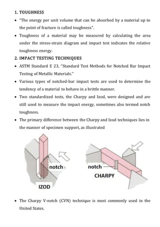
- 1. 1. TOUGHNESS “The energy per unit volume that can be absorbed by a material up to the point of fracture is called toughness”. Toughness of a material may be measured by calculating the area under the stress-strain diagram and impact test indicates the relative toughness energy. 2. IMPACT TESTING TECHNIQUES ASTM Standard E 23, ‘‘Standard Test Methods for Notched Bar Impact Testing of Metallic Materials.’’ Various types of notched-bar impact tests are used to determine the tendency of a material to behave in a brittle manner. Two standardized tests, the Charpy and Izod, were designed and are still used to measure the impact energy, sometimes also termed notch toughness. The primary difference between the Charpy and Izod techniques lies in the manner of specimen support, as illustrated The Charpy V-notch (CVN) technique is most commonly used in the United States.
- 2. For both Charpy and Izod, the specimen is in the shape of a bar of square cross section, into which a V-notch is machined as shown in figure. Figure: Specimen used for charpy and izod impact test The apparatus for making V-notch impact tests is illustrated schematically in Figure 9.19b.
- 3. The load is applied as an impact blow from a weighted pendulum hammer that is released from a cocked (tilt) position at a fixed height h. The specimen is positioned at the base as shown. Upon release, a knife edge mounted on the pendulum strikes and fractures the specimen at the notch, which acts as a point of stress concentration for this high velocity impact blow. The pendulum continues its swing, rising to a maximum height h’, which is lower than h. The energy absorption, computed from the difference between h and h’, is a measure of the impact energy.
- 4. Furthermore, these are termed impact tests in light of the manner of load application. Variables including specimen size and shape as well as notch configuration and depth influence the test results. v- notch test:( calculate energy by using formula) There is a formula which is used to measure the toughness if the equipment is not computerized. E = Pl (COSα2 - COSα1) Where E = Energy absorbed by a material, joules P = Weight of the pendulum, Kg l = length of the pendulum, m α2 = lift angle, degree α1 = Breaking angle, degree Example: A MS sample is subjected to impact test, calculate the absorbed energy of the specimen if the breaking angle is 100o. The configuration of the impact tester is: Weight of the pendulum 26.72Kg, Length of the pendulum 0.750m and lift angle 140.5o.
- 5. 3. SIGNIFICANCE OF FRACTURE TOUGHNESS: Impact test gives quantitative comparative useful data with relative simple test specimens and equipment. However this test does not provide property data for design purpose for material selection containing cracks and flaws. Or The chief difficulty is that the result of the charpy test are difficult to use in design, since there is no measurement in terms of stress level, moreover there is no correlation of charpy data with flaw size. Fracture toughness values can be used in mechanical design to predict the allowable flaw size in alloy with limited ductility when acted upon by specific stresses.
- 6. 4. INTRODUCTION TO FRACTURE TOUGHNESS Fracture toughness is a quantitative way of expressing a material's resistance to brittle fracture when a crack is present. If a material has much fracture toughness it will probably undergo ductile fracture. Brittle fracture is very characteristic of materials with less fracture toughness Definition: A property that is a measure of a material’s resistance to brittle fracture when a crack is present. Or Fracture toughness is a property which describes the ability of a material containing a crack to resist fracture, and is one of the most important properties of any material for virtually all design applications. Or Fracture toughness is an indication of the amount of stress required to propagate a preexisting flaw. It is a very important material property since the occurrence of flaws is not completely avoidable in the processing, fabrication, or service of a material/component Or Flaws may appear as cracks, voids, metallurgical inclusions, weld defects, design discontinuities, or some combination thereof. Since engineers can never be totally sure that a material is flaw free, it is common practice to assume that a flaw of some chosen size will be present in some number of components and use the linear elastic fracture mechanics (LEFM) approach to design critical components.
- 7. This approach uses the flaw size and features, component geometry, loading conditions and the material property called fracture toughness to evaluate the ability of a component containing a flaw to resist fracture. A parameter called the stress-intensity factor (K) is used to determine the fracture toughness of most materials STRESS INTENSITY FACTOR K: The stress intensity factor, , is used in fracture mechanics to predict the stress state ("stress intensity") near the tip of a crack caused by a remote load or residual stresses The stress-distribution at the crack tip in a thin plate for an elastic solid in terms of the coordinate shown in figure11-2
- 8. In dealing with the stress intensity factor there are several mode of deformation that could be applied to a crack. These have been standardized as shown in figure11-3(dieter) or figure 9.9(calister).
- 9. Mode I: the crack opening mode, refer to a tensile stress applied in the y- direction normal to the faces of the crack. This is the usual mode for fracture-toughness test and the critical value of stress-intensity determined for this mode would be designated KIC. Mode II: the forward shear mode, refer to s shear stress applied normal to the leading edge of the crack but in the plane of the crack. Mode III: theparallel shear mode is for shearing stresses applied parallel to the leading edge of the crack. The stress intensity factor is a function of loading, crack size, and structural geometry. The stress intensity factor may be represented by the following equation: Where: KI is the fracture toughnessin σ is the applied stress in MPa or psi a is the crack length in meters or inches β is a crack length and component geometry factor that is different for each specimen and is dimensionless. The critical value of the stress-intensity factor (KI) that cause failure of the plate is called the fracture toughness (KIC) of the material KIC = Y σ√πa Or Fracture toughness KIC has the unusual units MPa√m and ksi√in or psi√in
- 10. Y or f is a dimensionless parameter or function that depends on both crack and specimen sizes and geometries, as well as the manner of load application. Relative to this Y parameter, for planar specimens containing cracks that are much shorter than the specimen width, Y has a value of approximately unity. For example, for a plate of infinite width having a through-thickness crack (Figure 9.11a), Y = 1.0; whereas for a plate of semi-infinite width containing an edge crack of length a (Figure 9.11b), Y ≈ 1.12. Mathematical expressions for Y have been determined for a variety of crack-specimen geometries; these expressions are often relatively complex. For relatively thin specimens, the value of Kc will depend on specimen thickness. However, when specimen thickness is much greater than the crack dimensions, Kc becomes independent of thickness; under these conditions a condition of plane strain exists.
- 11. By plane strain we mean that when a load operates on a crack in the manner represented in Figure 9.11a, there is no strain component perpendicular to the front and back faces. The Kc value for this thick- specimen situation is known as the plane strain fracture toughness KIc ; {the crack-extension resistance under conditions of crack-tip plane strain(Mode I)}. furthermore, it is also defined by KIC = Y σ√πa 5. Problems related to Fracture toughness: Example 1 A structural plate component of an engineering design must support 207MPa in tension. If aluminum alloy 2024-T851 is used for this application what is the largest internal flaw size that this material can support? Use Y=1 and KIC of that alloy is 26.4Mpa√m. Formula: KIC = Y σ√πa Ans: the largest internal crack size that plate can support = 10.36mm
- 12. Example 2 The critical stress intensity for a material for a component of a design is 22.5Ksi√in. What is the applied stress that will cause fracture if the component contains an internal crack 0.12in long? Assume Y=1. Ans: 51.8Ksi Example 3 What is the largest size (inches) internal crack that a thick plate of aluminum alloy 7178-T651 can support at an applied stress of (a) ¾ of the yield strength and (b) 1/2 of the yield strength? Assume Y=1. Hint: Material KIC σ, Yield strength MPa√m Ksi√in MPa Ksi Aluminum Alloy” 2024-T851 26.4 24 455 66 7075-T651 24.2 22 495 72 7178-T651 23.1 21 570 83 Ans: (a) 0.072in (b) 0.163in
- 13. 6. Stress intensity factors for fracture toughness tests I. Compact tension specimen
- 14. II. Single edge notch bending specimen
- 15. 7. Standards 1. ASTM E399-09: 'Standard Test Method for Plane Strain Fracture Toughness of Metallic Materials'. American Society of Testing and Materials, Philadelphia, 2009. 2. ASTM E1290-09: 'Standard Test Method for Crack-Tip Opening Displacement (CTOD) Fracture Toughness Measurement'. American Society of Testing and Materials, Philadelphia, 2009 3. ASTM E1820-09: 'Standard Test Method for Measurement for Fracture Toughness'. American Society of Testing and Materials, Philadelphia, 2009. 4. ASTM E1823-09: 'Technology Relating to Fatigue and Fracture Testing'. American Society for Testing and Materials, Philadelphia, 2009. 5. ASTM E1921-09 'Standard Test Method for Determination of Reference Temperature, T0, for Ferritic Steels in the Transition Range'. American Society of Testing and Materials, Philadelphia, 2009 6. ESIS P1-92: 'ESIS Recommendation for Determining the Fracture Resistance of Ductile Materials' European Structural Integrity Society, 1992. 7. ESIS P2-92: 'ESIS Procedure for Determining the Fracture Behaviour of Materials'. European Structural Integrity Society, 1992. 8. DNV-RP-F108: 'Fracture control for pipeline installation methods introducing cyclic plastic strain'. Det Norske Veritas, January 2006. 9. DNV-OS-F101: 'Submarine pipeline systems'. Det Norske Veritas, October 2007
- 16. 8. Orientation The fracture toughness of a material commonly varies with grain direction. Therefore, it is customary to specify specimen and crack orientations by an ordered pair of grain direction symbols. The first letter designates the grain direction normal to the crack plane. The second letter designates the grain direction parallel to the fracture plane. For flat sections of various products, e.g., plate, extrusions, forgings, etc., in which the three grain directions are designated (L) longitudinal, (T) transverse, and (S) short transverse, the six principal fracture path directions are: L-T, L-S, T-L, T-S, S-L and S-T.
- 17. 9. Role of Material Thickness Specimens having standard proportions but different absolute size produce different values for KI. This results because the stress states adjacent to the flaw changes with the specimen thickness (B) until the thickness exceeds some critical dimension. Once the thickness exceeds the critical dimension, the value of KI becomes relatively constant and this value, KIC , is a true material property which is called the plane-strain fracture toughness. The relationship between stress intensity, KI, and fracture toughness, KIC, is similar to the relationship between stress and tensile stress. The stress intensity, KI, represents the level of “stress” at the tip of the crack and the fracture toughness, KIC, is the highest value of stress intensity that a material under very specific (plane-strain) conditions that a material can withstand without fracture. As the stress intensity factor reaches the KIC value, unstable fracture occurs. As with a material’s other mechanical properties, KIC is commonly reported in reference books and other sources.
- 18. i. Plane Strain - a condition of a body in which the displacements of all points in the body are parallel to a given plane, and the values of theses displacements do not depend on the distance perpendicular to the plane ii. Plane Stress – a condition of a body in which the state of stress is such that two of the principal stresses are always parallel to a given plane and are constant in the normal direction 10. Plane-Strain and Plane-Stress When a material with a crack is loaded in tension, the materials develop plastic strains as the yield stress is exceeded in the region near the crack tip. Material within the crack tip stress field, situated close to a free surface, can deform laterally (in the z-direction of the image) because there can be no stresses normal to the free surface. The state of stress tends to biaxial and the material fractures in a characteristic ductile manner, with a 45o shear lip being formed at each free surface. This condition is called “plane-stress" and it occurs in relatively thin bodies where the stress through the thickness cannot vary appreciably due to the thin section. However, material away from the free surfaces of a relatively thick component is not free to deform laterally as it is constrained by the surrounding material. The stress state under these conditions tends to triaxial and there is zero strain perpendicular to both the stress axis and the direction of crack propagation when a material is loaded in tension. This condition is called “plane-strain”
- 19. and is found in thick plates. Under plane-strain conditions, materials behave essentially elastic until the fracture stress is reached and then rapid fracture occurs. Since little or no plastic deformation is noted, this mode fracture is termed brittle fracture.