Downloaded 171 times


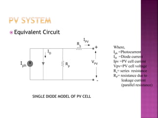
![𝐼 𝑃𝑉= Iph-Is[exp(q(Vpv+IpvRs)/KTcA)-1]-(Vpv+IpvRs)/Rp
Iph=[Isc+Ki(Tc-TRef)]ß/1000
Is(t)=Is(Tc-TRef)3exp[qEg(1/Tref-1/Tc)/KA]
Where,
Is=Reverse saturation current
q= charge of electrone
K=Boltzmann constant
A= Ideality factor
Tc=
Tref=
ß= irradiance
Eg=band gap energy](https://image.slidesharecdn.com/bibhuseminar-150921070137-lva1-app6892/85/INTERLEAVED-BOOST-CONVERTER-FOR-PV-APPLICATION-7-320.jpg)
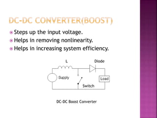
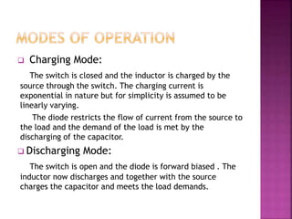

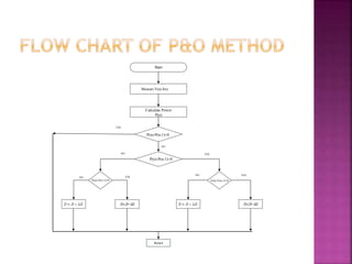
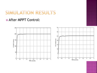

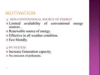
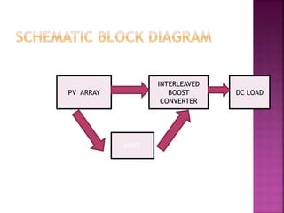
This document presents a schematic block diagram of a photovoltaic system with an interleaved boost converter and maximum power point tracking using the perturbation and observation method. It includes a single diode model of a PV cell and discusses the charging and discharging modes of operation of the boost converter. Simulation waveforms are presented showing the improvement with MPPT control. Future work will involve designing a closed loop inverter for grid synchronization.


