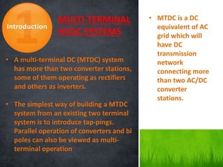
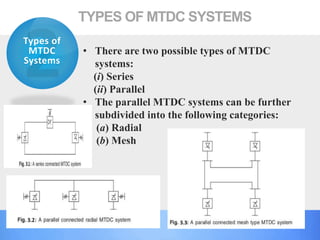
Downloaded 460 times


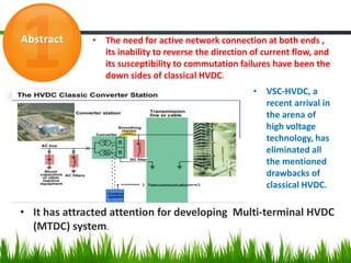


This document discusses multi-terminal DC (MTDC) systems. It begins with an introduction stating that MTDC systems have more than two converter stations that can operate as either rectifiers or inverters. It then describes the two types of MTDC systems - series and parallel (including radial and mesh configurations). The document outlines some applications of MTDC systems, as well as typical problems. It notes advantages like reversible power flow and lack of commutation failures, and disadvantages such as need for large smoothing reactors. Finally, it discusses future aspects like microgrids and renewable integration, and concludes that VSC-HVDC technology may help address challenges and enable more MTDC system implementation.


