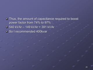
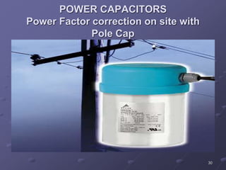
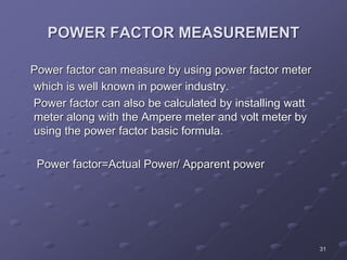
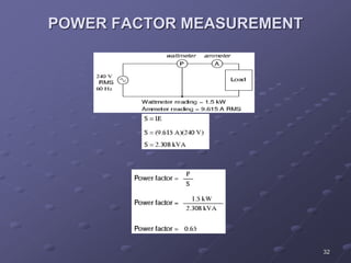
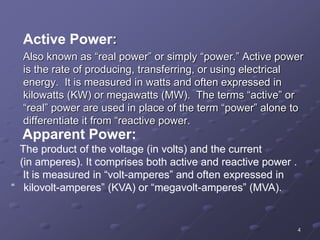
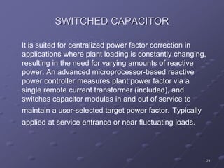
Power factor is the ratio of actual power to apparent power. A low power factor means more current is needed to deliver the same amount of useful power, resulting in higher costs. Power factor can be corrected by installing capacitors to offset the reactive power drawn by inductive loads. Improving power factor reduces line losses, increases system capacity, lowers utility bills, and improves voltage stability and equipment lifespan. Proper sizing and placement of power capacitors is needed to boost power factor from a facility's initial level to the target level required by the utility.
The apparatus used for switching, controlling & protecting the electrical circuits & equipments are known as switchgear.
The switchgear equipments is essentially used with switching & interrupting currents either under normal or abnormal operating condition.
It consists of devices such as switches, fuses, circuit breakers, relays etc.
Basically every electric circuit needs a switching device & a protecting device.
In electrical engineering, a protective relay is a relay device designed to trip a circuit breaker when a fault is detected. The theory and application of these protective devices is an important part of the education of a power engineer who specializes in power system protection.
This presentation provides information about different types of protective relaying system.
In microgrid, if fault occurs or any other contingency happens, then the problems would be created which are related to power flow, also there are various protection schemes are used for minimize or eliminate these problems.
Voltage control is used for reactive power balance and P-f control is used for active power control.
Various protection schemes such as, over current protection, differential protection scheme, zoning of network in adaptive protection scheme are used in microgrid system .
The cosine of angle made between the voltage and current is called the power factor.
In AC circuits, there is always the phase deference between the voltage and current, which is calculated in terms of power factor.
If the load is inductive the current lags behind the voltage and the power factor is lagging.
If the load is capacitive the current leads the voltage and the power factor is leading.
The value of power factor can never be more than unity.
Electrical Substations and Switchyard DesignLiving Online
Electrical substations form important nodal points in all power networks. Substations can be of various capacities, voltages, configurations and types depending on what is the application for which the substation is being designed. Location and layout of a substation present a number of challenges to the designer due to a large variety of options available to a designer. There are ever so many constraints too that need to be kept in mind; technical, environmental and naturally financial. Arriving at an optimum design within these constraints is as much an art as it is a science. Designing a substation which will operate with utmost reliability for at the least three or four decades involves a thorough knowledge of the current state-of-the art equipment, emerging technologies, the tools for presenting and evaluating all available options and a good appreciation of power system operation and maintenance. This course will present a comprehensive capsule of all the knowledge essential for a substation designer and walk the participants through the substation design process using a set of interlinked case studies.
WHO SHOULD ATTEND?
This course is aimed at engineers who are already working as electrical system designers as well as those who belong to any of the fields listed below and wish to prepare themselves for moving into the role of a substation designer.
Utility engineers dealing with power transmission and distribution systems
Electrical engineers involved in power generating plants with utility scale generators
Electrical engineers in large industries who are associated with power distribution
Consulting engineers involved in design of substations
Contractors executing projects involving electrical HV substations
Electrical commissioning engineers
MORE INFORMATION: http://www.idc-online.com/content/electrical-substation-and-switchyard-design-25
Practical handbook-for-relay-protection-engineersSARAVANAN A
The ‘Hand Book’ covers the Code of Practice in Protection Circuitry including standard lead and device numbers, mode of connections at terminal strips, colour codes in multicore cables, Dos and Donts in execution. Also, principles of various protective relays and schemes including special protection schemes like differential,
restricted, directional and distance relays are explained with sketches. The norms of protection of generators, transformers, lines & Capacitor Banks are also given.
Relay coordination is used to achieve proper fault identification and fault clearance sequence.These relays must be able to differentiate between the normal operating currents that including short time over currents that may appear due to certain equipment normal operation such as motor starting currents, Transformer inrush currents and sustained over current due to fault conditions
Installation, Testing and Troubleshooting of TransformersLiving Online
This will provide you with practical knowledge (including tips, tricks and tools) covering the fundamentals of power transformers and their testing. It will greatly assist you in communicating more effectively with your electrical engineering colleagues. At the end of this workshop, participants will be familiar with the importance of transformer testing and their purpose, the different kinds of transformer tests and their procedures and the practical applications of principals applied in transformer operation and maintenance.
WHO SHOULD ATTEND?
This workshop will be appropriate for the following professionals:
Electrical engineers
Maintenance engineers
Maintenance supervisors
Power electricians
Power engineers
MORE INFORMATION: http://www.idc-online.com/content/installation-testing-and-troubleshooting-transformers-24
the ratio of the actual electrical power dissipated by an AC circuit to the product of the r.m.s. values of current and voltage. The difference between the two is caused by reactance in the circuit and represents power that does no useful work.
Power Factor Correction Methods
Fixed Capcitors
Synchronous Condensors
Phase Advancers
Switch Capacitors
Static Var Compensator(SVC)
Static Synchronous Compensator(STATCOM)
Modulated power filter capacitor compensator
Economics of power factor improvement
Economical comparison of increasing the power supply
Reactive Power Compensation in 132kv & 33kv Grid of Narsinghpur Areaijceronline
Power Sector is considered to be very important and priority sector as it leads to overall development of country. The cost of installation of new generating units is rising; hence generated electrical energy has to be utilized carefully and efficiently, which changes through each AC cycle. It is proposed to study the effect of group shunt compensation provided for the mix of rural and urban loads, catered from grid sub-stations in the district of Narsinghpur, to assess its adequacy and saving in transmission losses. An optimum combination of compensators which yields maximum benefits in the system shall be worked out. Load Flow Study for the effect of group shunt compensation provided on 132KV bus of 220KV sub-station Narsinghpur and on 33KV buses of 132KV sub stations Srinagar, Narsinghpur, Gadarwara and Burman sub-stations for the mix of rural and urban loads, catered from partial grid network in Narsinghpur district. If reactive power is supplied near the load, the line current can be reduced or minimized, reducing power losses and improving voltage regulation at the load terminals. The leading current drawn by the shunt capacitors compensates the lagging current drawn by the load. The selection of shunt capacitors depends on many factors, the most important of which is the amount of lagging reactive power taken by the load. Objective was to study the effect of group shunt compensation provided for the mix of rural and urban loads, catered from grid sub-stations in the district of Narsinghpur and to assess the adequacy and saving in transmission losses & to work out an optimum combination of compensators which yields maximum benefits in the system. Depending on the stages of 'ON' and 'OFF', operations to be carried out in various permutations and combinations of shunt compensators i.e. switchable capacitor banks provided on 132 KV bus of 220KV substation Narsinghpur and on 33KV buses of 132 KV substations
Application of Capacitors to Distribution System and Voltage RegulationAmeen San
Application of Capacitors to
Distribution System and Voltage
Regulation
POWER FACTOR IMPROVEMENT,
System Harmonics
Voltage Regulation
Methods of Voltage Control
Sachpazis:Terzaghi Bearing Capacity Estimation in simple terms with Calculati...Dr.Costas Sachpazis
Terzaghi's soil bearing capacity theory, developed by Karl Terzaghi, is a fundamental principle in geotechnical engineering used to determine the bearing capacity of shallow foundations. This theory provides a method to calculate the ultimate bearing capacity of soil, which is the maximum load per unit area that the soil can support without undergoing shear failure. The Calculation HTML Code included.
NO1 Uk best vashikaran specialist in delhi vashikaran baba near me online vas...Amil Baba Dawood bangali
Contact with Dawood Bhai Just call on +92322-6382012 and we'll help you. We'll solve all your problems within 12 to 24 hours and with 101% guarantee and with astrology systematic. If you want to take any personal or professional advice then also you can call us on +92322-6382012 , ONLINE LOVE PROBLEM & Other all types of Daily Life Problem's.Then CALL or WHATSAPP us on +92322-6382012 and Get all these problems solutions here by Amil Baba DAWOOD BANGALI
#vashikaranspecialist #astrologer #palmistry #amliyaat #taweez #manpasandshadi #horoscope #spiritual #lovelife #lovespell #marriagespell#aamilbabainpakistan #amilbabainkarachi #powerfullblackmagicspell #kalajadumantarspecialist #realamilbaba #AmilbabainPakistan #astrologerincanada #astrologerindubai #lovespellsmaster #kalajaduspecialist #lovespellsthatwork #aamilbabainlahore#blackmagicformarriage #aamilbaba #kalajadu #kalailam #taweez #wazifaexpert #jadumantar #vashikaranspecialist #astrologer #palmistry #amliyaat #taweez #manpasandshadi #horoscope #spiritual #lovelife #lovespell #marriagespell#aamilbabainpakistan #amilbabainkarachi #powerfullblackmagicspell #kalajadumantarspecialist #realamilbaba #AmilbabainPakistan #astrologerincanada #astrologerindubai #lovespellsmaster #kalajaduspecialist #lovespellsthatwork #aamilbabainlahore #blackmagicforlove #blackmagicformarriage #aamilbaba #kalajadu #kalailam #taweez #wazifaexpert #jadumantar #vashikaranspecialist #astrologer #palmistry #amliyaat #taweez #manpasandshadi #horoscope #spiritual #lovelife #lovespell #marriagespell#aamilbabainpakistan #amilbabainkarachi #powerfullblackmagicspell #kalajadumantarspecialist #realamilbaba #AmilbabainPakistan #astrologerincanada #astrologerindubai #lovespellsmaster #kalajaduspecialist #lovespellsthatwork #aamilbabainlahore #Amilbabainuk #amilbabainspain #amilbabaindubai #Amilbabainnorway #amilbabainkrachi #amilbabainlahore #amilbabaingujranwalan #amilbabainislamabad
We have compiled the most important slides from each speaker's presentation. This year’s compilation, available for free, captures the key insights and contributions shared during the DfMAy 2024 conference.
Immunizing Image Classifiers Against Localized Adversary Attacksgerogepatton
This paper addresses the vulnerability of deep learning models, particularly convolutional neural networks
(CNN)s, to adversarial attacks and presents a proactive training technique designed to counter them. We
introduce a novel volumization algorithm, which transforms 2D images into 3D volumetric representations.
When combined with 3D convolution and deep curriculum learning optimization (CLO), itsignificantly improves
the immunity of models against localized universal attacks by up to 40%. We evaluate our proposed approach
using contemporary CNN architectures and the modified Canadian Institute for Advanced Research (CIFAR-10
and CIFAR-100) and ImageNet Large Scale Visual Recognition Challenge (ILSVRC12) datasets, showcasing
accuracy improvements over previous techniques. The results indicate that the combination of the volumetric
input and curriculum learning holds significant promise for mitigating adversarial attacks without necessitating
adversary training.
About
Indigenized remote control interface card suitable for MAFI system CCR equipment. Compatible for IDM8000 CCR. Backplane mounted serial and TCP/Ethernet communication module for CCR remote access. IDM 8000 CCR remote control on serial and TCP protocol.
• Remote control: Parallel or serial interface.
• Compatible with MAFI CCR system.
• Compatible with IDM8000 CCR.
• Compatible with Backplane mount serial communication.
• Compatible with commercial and Defence aviation CCR system.
• Remote control system for accessing CCR and allied system over serial or TCP.
• Indigenized local Support/presence in India.
• Easy in configuration using DIP switches.
Technical Specifications
Indigenized remote control interface card suitable for MAFI system CCR equipment. Compatible for IDM8000 CCR. Backplane mounted serial and TCP/Ethernet communication module for CCR remote access. IDM 8000 CCR remote control on serial and TCP protocol.
Key Features
Indigenized remote control interface card suitable for MAFI system CCR equipment. Compatible for IDM8000 CCR. Backplane mounted serial and TCP/Ethernet communication module for CCR remote access. IDM 8000 CCR remote control on serial and TCP protocol.
• Remote control: Parallel or serial interface
• Compatible with MAFI CCR system
• Copatiable with IDM8000 CCR
• Compatible with Backplane mount serial communication.
• Compatible with commercial and Defence aviation CCR system.
• Remote control system for accessing CCR and allied system over serial or TCP.
• Indigenized local Support/presence in India.
Application
• Remote control: Parallel or serial interface.
• Compatible with MAFI CCR system.
• Compatible with IDM8000 CCR.
• Compatible with Backplane mount serial communication.
• Compatible with commercial and Defence aviation CCR system.
• Remote control system for accessing CCR and allied system over serial or TCP.
• Indigenized local Support/presence in India.
• Easy in configuration using DIP switches.
Saudi Arabia stands as a titan in the global energy landscape, renowned for its abundant oil and gas resources. It's the largest exporter of petroleum and holds some of the world's most significant reserves. Let's delve into the top 10 oil and gas projects shaping Saudi Arabia's energy future in 2024.
Overview of the fundamental roles in Hydropower generation and the components involved in wider Electrical Engineering.
This paper presents the design and construction of hydroelectric dams from the hydrologist’s survey of the valley before construction, all aspects and involved disciplines, fluid dynamics, structural engineering, generation and mains frequency regulation to the very transmission of power through the network in the United Kingdom.
Author: Robbie Edward Sayers
Collaborators and co editors: Charlie Sims and Connor Healey.
(C) 2024 Robbie E. Sayers
Hybrid optimization of pumped hydro system and solar- Engr. Abdul-Azeez.pdffxintegritypublishin
Advancements in technology unveil a myriad of electrical and electronic breakthroughs geared towards efficiently harnessing limited resources to meet human energy demands. The optimization of hybrid solar PV panels and pumped hydro energy supply systems plays a pivotal role in utilizing natural resources effectively. This initiative not only benefits humanity but also fosters environmental sustainability. The study investigated the design optimization of these hybrid systems, focusing on understanding solar radiation patterns, identifying geographical influences on solar radiation, formulating a mathematical model for system optimization, and determining the optimal configuration of PV panels and pumped hydro storage. Through a comparative analysis approach and eight weeks of data collection, the study addressed key research questions related to solar radiation patterns and optimal system design. The findings highlighted regions with heightened solar radiation levels, showcasing substantial potential for power generation and emphasizing the system's efficiency. Optimizing system design significantly boosted power generation, promoted renewable energy utilization, and enhanced energy storage capacity. The study underscored the benefits of optimizing hybrid solar PV panels and pumped hydro energy supply systems for sustainable energy usage. Optimizing the design of solar PV panels and pumped hydro energy supply systems as examined across diverse climatic conditions in a developing country, not only enhances power generation but also improves the integration of renewable energy sources and boosts energy storage capacities, particularly beneficial for less economically prosperous regions. Additionally, the study provides valuable insights for advancing energy research in economically viable areas. Recommendations included conducting site-specific assessments, utilizing advanced modeling tools, implementing regular maintenance protocols, and enhancing communication among system components.
Final project report on grocery store management system..pdfKamal Acharya
In today’s fast-changing business environment, it’s extremely important to be able to respond to client needs in the most effective and timely manner. If your customers wish to see your business online and have instant access to your products or services.
Online Grocery Store is an e-commerce website, which retails various grocery products. This project allows viewing various products available enables registered users to purchase desired products instantly using Paytm, UPI payment processor (Instant Pay) and also can place order by using Cash on Delivery (Pay Later) option. This project provides an easy access to Administrators and Managers to view orders placed using Pay Later and Instant Pay options.
In order to develop an e-commerce website, a number of Technologies must be studied and understood. These include multi-tiered architecture, server and client-side scripting techniques, implementation technologies, programming language (such as PHP, HTML, CSS, JavaScript) and MySQL relational databases. This is a project with the objective to develop a basic website where a consumer is provided with a shopping cart website and also to know about the technologies used to develop such a website.
This document will discuss each of the underlying technologies to create and implement an e- commerce website.
Cosmetic shop management system project report.pdfKamal Acharya
Buying new cosmetic products is difficult. It can even be scary for those who have sensitive skin and are prone to skin trouble. The information needed to alleviate this problem is on the back of each product, but it's thought to interpret those ingredient lists unless you have a background in chemistry.
Instead of buying and hoping for the best, we can use data science to help us predict which products may be good fits for us. It includes various function programs to do the above mentioned tasks.
Data file handling has been effectively used in the program.
The automated cosmetic shop management system should deal with the automation of general workflow and administration process of the shop. The main processes of the system focus on customer's request where the system is able to search the most appropriate products and deliver it to the customers. It should help the employees to quickly identify the list of cosmetic product that have reached the minimum quantity and also keep a track of expired date for each cosmetic product. It should help the employees to find the rack number in which the product is placed.It is also Faster and more efficient way.
Using recycled concrete aggregates (RCA) for pavements is crucial to achieving sustainability. Implementing RCA for new pavement can minimize carbon footprint, conserve natural resources, reduce harmful emissions, and lower life cycle costs. Compared to natural aggregate (NA), RCA pavement has fewer comprehensive studies and sustainability assessments.
2. 2
OUTLINE
DEFINITION
CAUSES OF LOW POWER FACTOR
POWER FACTOR CORRECTION
ADVANTAGES OF POWER FACTOR CORRECTION
DISADVANTAGES OF LOW POWER FACTOR
CONCLUSION
REFERENCES
3. 3
DEFINITION:
Power factor (P.F) is the ratio between actual power to
the apparent power.
Actual power/Apparent power.
P.F=Kw /Kva.
For a purely resistive load the power factor is unity. Active
and reactive power are designated by P &Q respectively.
The average power in a circuit is called active power and
the power that supplies the stored energy in reactive
elements is called reactive power.
4. 4
Active Power:
Also known as “real power” or simply “power.” Active power
is the rate of producing, transferring, or using electrical
energy. It is measured in watts and often expressed in
kilowatts (KW) or megawatts (MW). The terms “active” or
“real” power are used in place of the term “power” alone to
differentiate it from “reactive power.
Apparent Power:
The product of the voltage (in volts) and the current
(in amperes). It comprises both active and reactive power .
It is measured in “volt-amperes” and often expressed in
“ kilovolt-amperes” (KVA) or “megavolt-amperes” (MVA).
5. 5
POWER FACTOR DEFINITION
Inductive loads cause the current to lag behind the
voltage. The wave forms of voltage and current are then
"out of phase" with each other. The more out of phase
they become then the lower the Power Factor. Power
Factor is usually expressed as Cos Phi. (Ø)
6. 6
Consider a canal boat being pulled by a horse.
If the horse could walk on water then the angle (Phi) Ø
would be zero and COSINE Ø=1. Meaning all the horse
power is being used to pull the load.
However the relative position of the horse influences the
power. As the horse gets closer to the barge, angle Ø1
increases and power is wasted, but, as the horse is
positioned further away, then angle Ø2 gets closer to
zero and less power is wasted.
7. 7
CAUSES OF LOW POWER FACTOR
A poor power factor can be the result of either a
significant phase difference between the voltage and
current at the load terminals or it can be due to a high
harmonic content or distorted/discontinuous current
waveform. Poor load current phase angle is generally the
result of Poor load current phase angle is generally the
result of an inductive load such as an induction motor
power transformer, lighting ballasts, welder or induction
furnace, Induction generators Wind mill generators and
high intensity discharge lightings.
8. 8
CAUSES OF LOW POWER FACTOR
A distorted current waveform can be the result of a
rectifier variable speed drive, switched mode power
supply, discharge lighting or other electronic load.
9. 9
POWER FACTOR CORRECTION
Power factor decreases with the installation of non
resistive loads such as induction motors, Transformers.
Lighting ballasts and electronic equipments. Power
factors can be corrected by using capacitors. These are
rated in electrical units called VAR or KVAR.One VAR is
equivalent to one volt of reactive power. VAR then are
units of measurement for indicating just how much
reactive power the capacitor will supply.
10. 10
As reactive power is usually measured in thousands the
letter K is used for thousand. the capacitor KVAR rating
then shows how much reactive power the capacitor will
supply. Each unit of the capacitor's KVAR will decrease
the inductive reactive power demand.
11. 11
POWER FACTOR CORRECTION
Most loads on an electrical distribution system fall into
one of three categories; resistive, inductive or capacitive.
In most plant, the most common is likely to be inductive.
Typical examples of this include transformers, fluorescent
lighting and AC induction motors. Most inductive loads
use a conductive coil winding to produce an
electromagnetic field, allowing the motor to function.
12. 12
All inductive loads require two kinds of power to operate:
Active power (KW) - to produce the motive force
Reactive power (KVAR) - to energize the magnetic field
The operating power from the distribution system is
composed of both active (working) and reactive (non-
working) elements. The active power does useful work in
driving the motor whereas the reactive power only
provides the magnetic field.
13. 13
POWER FACTOR CORRECTION
The amount of Power Capacitor KVAR required to correct
A system to a desired Power Factor level is the difference
between the amount of KVAR in the uncorrected system
and the amount of desired KVAR in the corrected system.
The most efficient location for power factor capacitors is
at the load. Capacitors work from the point of installation
back to the generating source. Individual motor correction
is not always practical, sometimes it is more practical to
connect larger capacitors on the distribution bus or install
an automatic system at the incoming service along with
fixed capacitors at the load.
14. 14
KVAR CORRECTION
Capacitive Power Factor correction (PFC) is applied to
electric circuits as a means of minimising the inductive
component of the current and thereby reducing the
losses in the supply.
The introduction of Power Factor Correction capacitors is
a widely recognised method of reducing an electrical
load, thus minimising wasted energy and hence
improving the efficiency of a plant and reducing the
electricity bill.
15. 15
It is not usually necessary to reach unity, i.e. Power
Factor 1, since most supply companies are happy with a
PF of 0.95 to 0.98.
By installing suitably sized switched capacitors into the
circuit, the Power Factor is improved and the value
becomes nearer to 1 thus minimising wasted energy and
improving the efficiency of a plant or power factor can be
increased by synchronous motor or Synchronous
generators.
16. 16
POWER FACTOR CORRECTION
METHODS
Static Var Compensator(SVC)
Fixed Capcitors
Switch Capacitors
Synchronous Condensors
Static Synchronous Compensator(STATCOM)
Modulated power filter capacitor compensator
17. 17
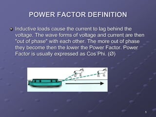
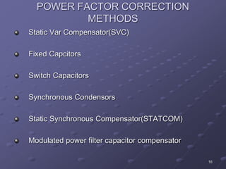
STATIC VAR COMPENSATOR
(SVC)
The Static Var Compensator (SVC) is a shunt device of
the Flexible AC Transmission Systems (FACTS) family
using power electronics to control power flow and
improve transient stability on power grids [1]. The SVC
regulates voltage at its terminals by controlling the
amount of reactive power injected into or absorbed from
the power system. When system voltage is low, the SVC
generates reactive power (SVC capacitive). When
system voltage is high, it absorbs reactive power (SVC
inductive).
18. 18
The variation of reactive power is performed by switching
three-phase capacitor banks and inductor banks
connected on the secondary side of a coupling
transformer. Each capacitor bank is switched on and off
by three thyristor switches (Thyristor Switched Capacitor
or TSC). Reactors are either switched on-off (Thyristor
Switched Reactor or TSR) or phase-controlled (Thyristor
Controlled Reactor or TCR).
19. 19
A rapidly operating Static Var Compensator (SVC) can
continuously provide the reactive power required to
control dynamic voltage swings under various system
conditions and thereby improve the power system
transmission and distribution performance.
Installing an SVC at one or more suitable points in the
network will increase transfer capability through
enhanced voltage stability, while maintaining a smooth
voltage profile under different network conditions. In
addition, an SVC can mitigate active power oscillations
through voltage amplitude modulation
20. 20
FIXED CAPACITOR
where the load does not change or where the capacitor
is switched with the load, such as the load side of a
Ideally suited for power factor correction in applications
motor contactor. It is suitable for locations using
induction motors, like food processing plants, or
where small multiple loads require reactive power
compensation.
Each Fixed Capacitor Bank is designed for high reliability
and long life. These products are designed for
applications that do not contain harmonic generating
21. 21
SWITCHED CAPACITOR
It is suited for centralized power factor correction in
applications where plant loading is constantly changing,
resulting in the need for varying amounts of reactive
power. An advanced microprocessor-based reactive
power controller measures plant power factor via a
single remote current transformer (included), and
switches capacitor modules in and out of service to
maintain a user-selected target power factor. Typically
applied at service entrance or near fluctuating loads.
22. 22
SYNCHRONOUS CONDENSER
Synchronous condenser is a salient pole synchronous
generator without prime mover. Synchronous condenser
stabilizes power system voltage by supplying reactive
power to the power system and Use for power factor
correction. It is more economical than capacitors.
24. 24
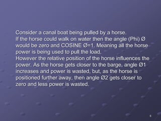
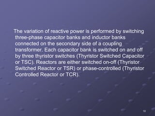
STATIC SYNCHRONOUS COMPENSTOR
(STATCOM)
The Static Synchronous Compensator (STATCOM) is a
shunt device of the Flexible AC Transmission Systems
(FACTS) family using power electronics to control power
flow and improve transient stability on power grids [1].
The STATCOM regulates voltage at its terminal by
controlling the amount of reactive power injected into or
absorbed from the power system. When system voltage
is low, the STATCOM generates reactive power
(STATCOM capacitive).
25. 25
When system voltage is high, it absorbs reactive power
(STATCOM inductive).Similarly to the SVC the
STATCOM can provide instantaneous and continuously
variable reactive power in response to grid voltage
transients enhancing the grid voltage stability
26. 26
Installing a STATCOM at one or more suitable points in
the network will increase the grid transfer capability
through enhanced voltage stability, while maintaining a
smooth voltage profile under different network
conditions. The STATCOM provides additional versatility
in terms of power quality improvement capabilities
27. 27
DETERMINING CAPACITOR VALUE
Example
Power Factor1=74%
Actual Power=594 kw
Interested to boost up=97% ,Power Factor2=97%
Power Factor=KW/KVA
Cos = kW / kVA
= Cos-1 (PF1)
= Cos-1 (74%) =42.27 o
28. 28
The reactive power was about:
Tan = kVAr / kW
kVAr = kW x tan
kVAr = 594 kW x tan (42.27) = 540 kVAr
If the power factor were increased to 97%, the reactive
power would be about:
Cos = kW / kVA
= Cos-1 (PF2)
= Cos-1 (97%) = 14.07 o
kVAr = kW x tan
kVAr = 594 kW x tan (14.07) = 149 kVAr
29. 29
Thus, the amount of capacitance required to boost
power factor from 74% to 97% :
540 kVAr – 149 kVAr = 391 kVAr
So I recommended 400kvar
31. 31
POWER FACTOR MEASUREMENT
Power factor can measure by using power factor meter
which is well known in power industry.
Power factor can also be calculated by installing watt
meter along with the Ampere meter and volt meter by
using the power factor basic formula.
Power factor=Actual Power/ Apparent power
33. 33
ADVANTAGES OF POWER FACTOR
CORRECTION
Eliminate Power Factor Penalties
Increase System Capacity
Reduce Line Losses in distribution systems
Conserve Energy
Improve voltage stability
35. 35
Reduction in size of transformers, cables and switchgear
in new installations.
Delay costly upgrades.
Less total plant KVA for the same KW working power.
Improved voltage regulation due to reduced line voltage
drop.
36. 36
POWER COST REDUCTION
Utility companies in many areas include a penalty charge in
the electrical rate for low power factor. The installation of
power factor capacitors on the user's electrical distribution
system eliminates the necessity of paying premium rates to
the utility company for poor power factor.
37. 37
The savings the utility company derives in reduced
generation, transmission and distribution costs are
passed on to the user in the form of lower electrical
charges. Three of the more common ways a utility
charges a user for poor power factor are based on
38. 38
KW demand with a trigger point typically between 85%
and 95%
KVA demand
KVAR demand
When the utility uses either KVA demand or KVAR
demand as the basis for its penalty structure, all users
pay a penalty, but those with high power factor pay a
much lower penalty or none at all.
39. 39
SYSTEM CAPACITY INCREASE
By adding capacitors to the system, the power factor is
improved and the KW capacity of the system is
increased. For example, a 1,000 KVA transformer with a
70% power factor provides 700 KW of power to the main
bus. With the installation of capacitors so that the power
factor is improved, say, to 90%, the KW capacity of the
system is increased to 900 KW. When a system power
factor is improved, the amount of reactive current flowing
Is lowered thus reducing transformer and distribution
circuit loads, and releasing system capacity.
40. 40
VOLTAGE IMPROVEMENT AND POWER
LOSS REDUCTION
System losses are also reduced through power factor
correction by reducing the total current and power in the
system. A 20% reduction in current will yield a 36%
reduction in distribution system losses. In this situation,
an energy savings of as much as 50% will be realized
with the installation of power factor capacitors.
In addition, power factor capacitors decrease the
distribution system voltage drops and fluctuations.
41. 41
DISADVANTAGES OF LOW POWER
FACTOR
Increases heating losses in the transformers and
distribution equipments.
Reduce plant life.
Unstabilise voltage levels.
Increase power losses.
Upgrade costly equipments.
Decrease energy efficiency.
Increase electricity costs by paying power factor
surcharges.
42. 42
CONCLUSION
By observing all aspects of the power factor it is clear that
power factor is the most significant part for the utility
Company as well as for the consumer. Utility company
rid of from the power losses while the consumer free
from low power factor penalty charges.
By installing suitably sized power capacitors into the
circuit the Power Factor is improved and the value
becomes nearer to 1 thus minimising line losses and
improving the efficiency of a plant.
43. 43
REFERENCES
Electrical Power System Design and Analysis
by M.E.EI-Hawary.
Power System Operations
by Robert H Miller.
IEEE papers
www.ABB.com
BC Hydro (www.bchydro.ca)