Downloaded 28 times
![5
CHAPTER 1
1.1 Introduction
This paper presents Photovoltaic (PV) cell model. Perturb & Observe and
fuzzy logic based Maximum Power Point Tracking (MPPT) algorithm for PV cell.
The solar cell is modelled and analyzed in MATLAB/SIMULINK. The Solar cell can
produce maximum power at a particular operating point called Maximum Power
Point (MPP).To produce maximum power and to get maximum efficiency, the
entire photovoltaic panel must operate at this particular point. Maximum power
point of PV cell keeps on changing with changing environmental conditions such
as solar irradiance and cell temperature. Thus to extract maximum available
power from a PV module, MPPT algorithms are implemented. In this paper,
Perturb and Observe (P&O) MPPT and fuzzy logic based MPPT are developed
and compared. Simulation results show the effectiveness of the fuzzy based
technique to produce a more stable power.
Keywords: MPPT, Fuzzy Logic, PV Modeling, Buck-Boost Converter, Perturb and
Observe.
1.2 Motivation
Renewable energy also called non-conventional type of energy sources are
the sources which are continuously replenished by natural processes. Solar
energy, bio-energy (bio-fuels grown sustainably), wind energy and hydropower
etc., are some of the examples of renewable energy sources [1]. A renewable
energy system convert the energy from sunlight, falling-water, wind, sea-waves,
geothermal heat, or biomass into a form, which we can use in the form of heat
or electricity. The majority of the renewable energy comes either directly or
indirectly from sun and wind and can never be fatigued, and therefore they are
called renewable.
However, the majority of the world's energy sources came from conventional
sources- fossil fuels such as coal, natural gases and oil. These fuels are often
termed as non-renewable energy sources. Though, the available amount of
these fuels are extremely large, due to decrease in level of fossil fuel and oil level
day by day after a few years it will end. Hence the demand for renewable energy](https://image.slidesharecdn.com/fc6b2820-8804-43cc-a594-135634d6b833-160520075343/85/report3-5-320.jpg)

![7
CHAPTER 2
MODELING OF PHOTOVOLTAIC CELL
2.1 Introduction
A PV cells are made of semiconductor materials, such as silicon. For solar
cells, a thin semiconductor wafer is specially treated to form an electric field,
positive on one side and negative on the other. When light energy strikes the
solar cell, electrons are knocked loose from the atoms in the semiconductor
material [2]. If electrical conductors are attached to the positive and negative
sides, forming an electrical circuit, the electrons can be captured in the form of
an electric current that is, electricity .This electricity can then be used to power
a load.
2.2 Photovoltaic cell
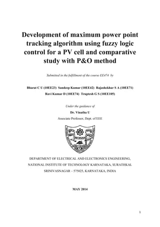
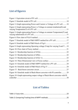
An ideal solar cell is modelled by a current source in parallel with a diode.
However no solar cell is ideal and thereby shunt and series resistances are added
to the model as shown in the Fig.1.
Figure 1: Equivalent circuit of PV cell
PV arrays produce electric power directly from sunlight. With the advent of
silicon P-N junction during the 1950s, the photoelectric current was able to
produce power due to the inherent voltage drop across the junction [3]. This](https://image.slidesharecdn.com/fc6b2820-8804-43cc-a594-135634d6b833-160520075343/85/report3-7-320.jpg)
![8
gives the well-known nonlinear relationship between the current and voltage of
the photovoltaic cell. From this nonlinear relationship of the photovoltaic cell, it
can be observed that there is a unique point, under given illumination, at which
the cell produces maximum power, the so-called maximum power point (MPP).
This point occurs when the rate of change of the power with respect to the
voltage is equal to zero [4].
The current source Ipv represents the cell photo current, Rsh and Rs are used to
represent the intrinsic series and shunt resistance of the cell respectively.
Usually the value of Rsh is very large and that of Rs is very small, hence they may
be neglected to simplify the analysis
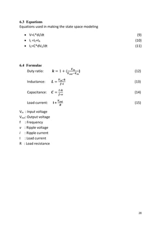
2.3 Equations governing PV cell
The PV mathematical model used to simplify our PV array is represented
by the Eqn(1):
Ia= npIph - npI0[𝑒−
𝑞(𝑉a/ns+IaRs)
𝑛𝑘𝑇 -1] -
𝑉a
𝑛𝑠⁄ +𝐼𝑠ℎ𝑅𝑠
𝑅𝑠ℎ
(1)
Ia : Cell output current
Va : Cell output voltage
np : Number of parallel solar cells
ns : Number of series solar cells
Iph : Photon current
I0 :Solar cell’s reverse saturation current. (0.0003A)
q : Electron charge. (1.6 ×10⁻¹⁹ C)
n :P-N junction ideality factor (Between 1and 5)
k : Boltzmann’s constant. (1.38×10⁻²³
J/K)
T : Solar cell operating temperature
Rs :Cell intrinsic series resistance
Rsh : Cell intrinsic parallel resistance
Photon current equation is given by:
Iph = Isc(
𝑆
1000
) + CT( T - Tref ) (2)](https://image.slidesharecdn.com/fc6b2820-8804-43cc-a594-135634d6b833-160520075343/85/report3-8-320.jpg)
![9
Isc :Short circuit current at standard testing condition .(5A)
S :Operating solar radiation (W/m2)
CT :Short-circuit-current temperature coefficient. (0.0016A/K)
T :Operating temperature
Tref :Solar cell absolute temperature at standard testing condition (STC) (20°C)
From the Eq.1 & 2 simulation of PV module can be done, in following manner,
Taking, Rsh=∞, np=1, ns=1, Rs=0 the equation becomes
Ia= Iph – I0[𝑒−
𝑞𝑉a
𝑛𝑘𝑇 -1] (3)
The PV cell output voltage is a function of the photocurrent that mainly
determined by load current depending on the solar irradiation level during the
operation.
Va =
𝑛𝑘𝑇
𝑞
ln(
𝐼𝑝ℎ+𝐼𝑟𝑠−𝐼𝑎
𝐼𝑟𝑠
) (4)
Both k and T should have the same temperature unit, either Kelvin or Celsius.
When the ambient temperature and irradiation levels change, the cell operating
temperature also changes, resulting in a new output voltage and a new
photocurrent value. The solar cell operating temperature varies as a function of
solar irradiation level and ambient temperature. The variable ambient
temperature T affects the cell output voltage and cell photocurrent.
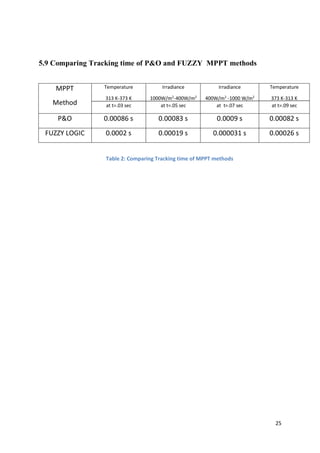
2.4 MATLAB Simulink model of PV cell
Solar irradiation (S) and temperature (T) are the input to the PV cell.
current (Ia), voltage (Va) and power (P) are the output of the PV cell. Va is
incremented/ decremented by the factor 0.01 at each step. PV cell model
identifies any change in S or T and recalculates the voltage, current and power.
For S=400W/m2
T=373 K](https://image.slidesharecdn.com/fc6b2820-8804-43cc-a594-135634d6b833-160520075343/85/report3-9-320.jpg)

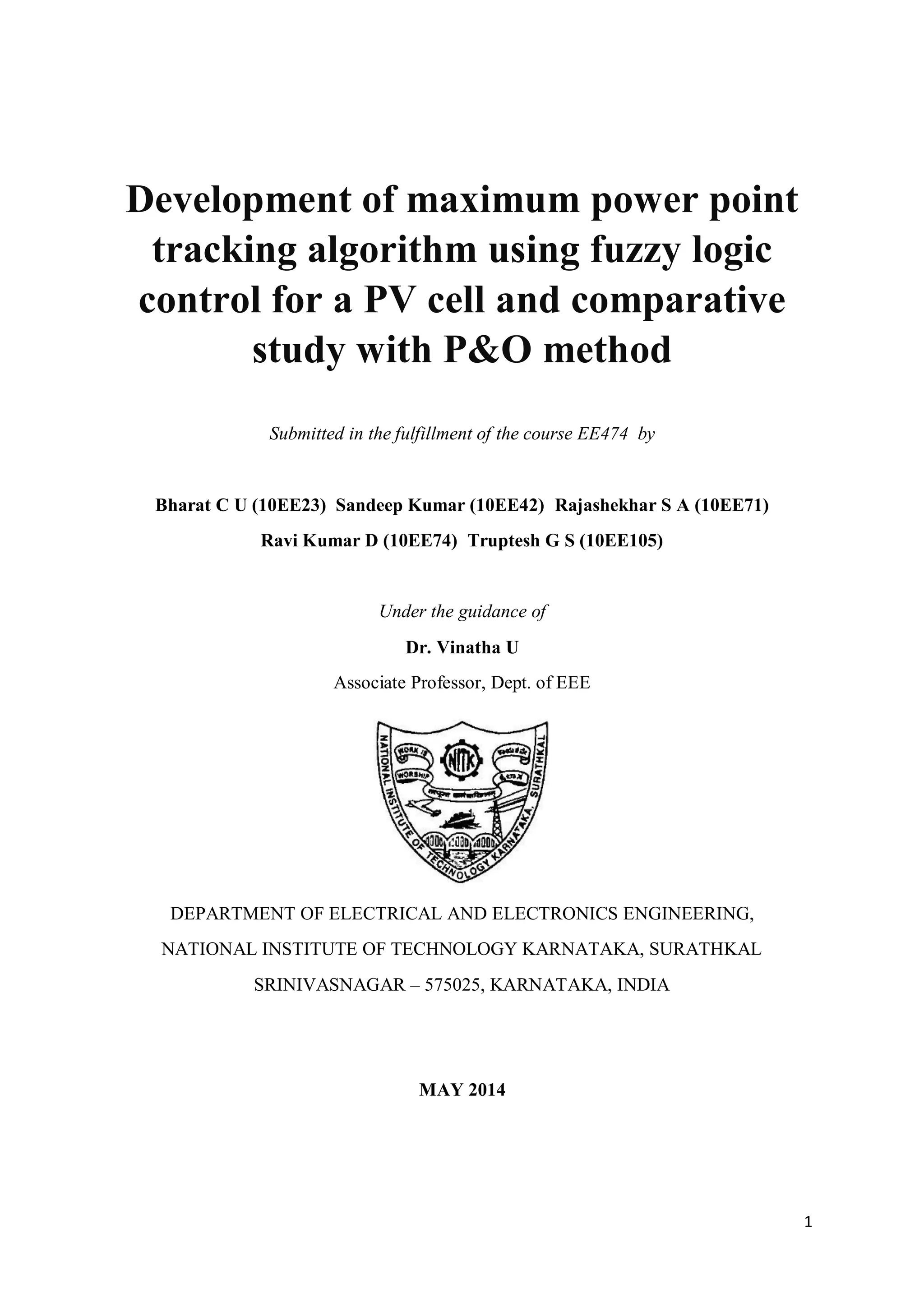
![11
PV cell inputs S=400 W/m2 and different values of T=[293 313 333 353 373] K is
simulated and graph between power and voltage is shown in Fig.4. Power
increases with increase in temperature.
Figure 4: Graph representing Power vs Voltage at constant irradiation(S) and varying
Temperature(T) of a PV cell
PV cell inputs different values of S=[200 400 600 800 1000] W/m2 and T=313K
is simulated and graph between power and voltage is shown in Fig.5. Power
increases with increase in irradiation.
Figure 5: Graph representing Power vs Voltage at constant Temperature(T) and varying
radiation(S) of a PV cell](https://image.slidesharecdn.com/fc6b2820-8804-43cc-a594-135634d6b833-160520075343/85/report3-11-320.jpg)
![12
CHAPTER 3
MAXIMUM POWER POINT TRACKING
3.1 Introduction
From the nonlinear relationship between the current and voltage of the
photovoltaic cell it can be observed that there is a unique point, under given
illumination, at which the cell produces maximum power, the so-called
maximum power point (MPP). This point occurs when the rate of change of the
power with respect to the voltage is equal to zero [4].
The output power of PV cell varies with depending mainly on the level of solar
radiation and ambient temperature corresponding to a specific weather
condition. The MPP will change with external environment of PV cell. An
important consideration in achieving high efficiency in PV power generation
system is to match the PV source and load impedance properly for any weather
conditions, thus obtaining maximum power generation.
3.2 Methods for MPPT
The different methods used to track the maximum power point are:
(i) Perturb and Observe method
(ii) Incremental Conductance method
(iii) Parasitic Capacitance method
(iv) Constant Voltage method
(v) Fuzzy Control method](https://image.slidesharecdn.com/fc6b2820-8804-43cc-a594-135634d6b833-160520075343/85/report3-12-320.jpg)
![13
3.2.1 Perturb and observe method
This method is the most common. In this method very less number of
sensors are utilized [5] and [6]. The operating voltage is sampled and the
algorithm changes the operating voltage in the required direction and samples
𝑑𝑃/𝑑𝑉. If 𝑑𝑃/𝑑𝑉 is positive, then the algorithm increases the voltage value
towards the MPP until 𝑑𝑃/𝑑𝑉is negative. This iteration is continued until the
algorithm finally reaches the MPP. This algorithm is not suitable when the
variation in the solar irradiation is high. The voltage never actually reaches an
exact value but perturbs around the maximum power point (MPP).
3.2.2 Incremental conductance method
This method uses the PV array's incremental conductance 𝑑𝐼𝑑𝑉to
compute the sign of𝑑𝑃 𝑑𝑉. When 𝑑𝐼𝑑𝑉is equal and opposite to the value of I/V
(where 𝑑𝑃𝑑𝑉=0) the algorithm knows that the maximum power point is reached
and thus it terminates and returns the corresponding value of operating voltage
for MPP. This method tracks rapidly changing irradiation conditions more
accurately than P&O method. One complexity in this method is that it requires
many sensors to operate and hence is economically less effective [5] and [6].
3.2.3 Parasitic capacitance method
This method is an improved version of the incremental conductance
method, with the improvement being that the effect of the PV cell's parasitic
union capacitance is included into the voltage calculation [5] and [6].
3.2.4 Constant voltage method
This method which is a not so widely used method because of the losses
during operation is dependent on the relation between the open circuit voltage
and the maximum power point voltage. The ratio of these two voltages is
generally constant for a solar cell, roughly around 0.76. Thus the open circuit
voltage is obtained experimentally and the operating voltage is adjusted to 76%
of this value [8].](https://image.slidesharecdn.com/fc6b2820-8804-43cc-a594-135634d6b833-160520075343/85/report3-13-320.jpg)
![14
3.2.5 Fuzzy control methods
A MPP search based on fuzzy heuristic rules, which does not need any parameter
information, consists of a stepwise adaptive search, leads to fast convergence
and is sensor less with respect to sunlight and temperature measurements [9].
The control objective is to track and extract maximum power from the PV arrays
for a given solar insolation level. The maximum power corresponding to the
optimum operating point is determined for a different solar insolation level and
temperature.](https://image.slidesharecdn.com/fc6b2820-8804-43cc-a594-135634d6b833-160520075343/85/report3-14-320.jpg)
![15
CHAPTER 4
DETAILED ANALYSIS OF PERTURB AND OBSERVE METHOD
4.1 Introduction
One of the most simple and popular techniques of MPPT is the P&O
technique. The main concept of this method is to push the system to operate at
the direction which the output power obtained from the PV system increases.
Following equation describes the change of power which defines the strategy of
the P&O technique
∆P = P(k) – P(k-1) (5)
∆V= V(k) – V(k-1) (6)
If the change of power defined by (5) is positive, the system will keep the
direction of the incremental voltage (increase or decrease the PV voltage) as the
same direction, and if the change is negative, the system will change the
direction of incremental voltage command to the opposite direction.[5]
The flow chart of the P&O algorithm is shown in Fig.6](https://image.slidesharecdn.com/fc6b2820-8804-43cc-a594-135634d6b833-160520075343/85/report3-15-320.jpg)


![19
CHAPTER 5
DETAILED ANALYSIS OF FUZZY LOGIC METHOD
5.1 Introduction
In recent years, fuzzy logic controllers have been widely used for industrial
processes owing to their heuristic nature associated with simplicity and
effectiveness for both linear and nonlinear systems [6]. A MPP search based on
fuzzy heuristic rules, which does not need any parameter information, consists
of a stepwise adaptive search, leads to fast convergence and is sensor less with
respect to sunlight and temperature measurements [7]. The control objective is
to track and extract maximum power from the PV arrays for a given solar
insolation level. The maximum power corresponding to the optimum operating
point is determined for a different solar insolation level and temperature.
5.2 The fuzzy controller’s functional blocks
5.2.1 Fuzzification
The fuzzy control requires that variable used in describing the control rules
has to be expressed in terms of fuzzy set notations with linguistic labels. In this
paper, the fuzzy control MPPT method has two input variables, namely ΔP(k)
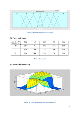
and ΔV(k), at a sampling instant k. The output variable is ΔV(k+1), which is
voltage’s increase of PV array at next sampling instant k+1. The variable ΔP(k)
and ΔV(k) are expressed as follows:
ΔP(k)=P(k)-P(k-1) (5)
ΔV(k)=V(k)-V(k-1) (6)
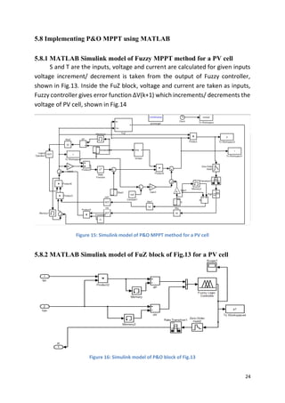
5.2.2 Fuzzy rule algorithm
The rule base that associates the fuzzy output to the fuzzy inputs is
derived by understanding the system behavior. In this paper, the fuzzy rules
are designed to incorporate the following considerations keeping in view the
overall tracking performance.](https://image.slidesharecdn.com/fc6b2820-8804-43cc-a594-135634d6b833-160520075343/85/report3-19-320.jpg)
![20
5.2.3 Defuzzification
After the rules have been evaluated, the last step to complete the fuzzy
control algorithm is to calculate the crisp output of the fuzzy control with the
process of defuzzification. The well-known center of gravity method for
defuzzification is used in this paper. It computes the center of gravity from the
final fuzzy space, and yields a result which is highly related to all of the elements
in the same fuzzy set [9]. The crisp value of control output ΔV(k+1) is computed
by the following equation:
∆𝑉 = ∑
𝑊𝑖∆𝑉𝑖
𝑊𝑖
𝑛
𝑖=1 (7)
Where n is the maximum number of effective rules, Wi is the weighting factor,
and ΔVi is the value corresponding to the membership function of ΔV. Then,
the final control voltage is obtained by adding this change to the previous
value of the control voltage:
V(k+1)=V(k) + ΔV (8)
5.3 Fuzzy controller steps
(a) If the last change in voltage ΔV(k) has caused the power to rise, keep moving
the next change in voltage ΔV(k+1) in the same direction by tuning duty ratio of
converter to achieve, otherwise, if it has caused the power to drop, move it in
the opposite direction.
(b) Owing to the fact that the characteristic curves might change with
temperature and sunlight level, leading to an overall shift of the optimum point.
(c) Because the optimum point tends to satisfy the condition əP/əV=0, the
system might recognize any large plateau as a maximum power region and stop.
The some rules have been identified for avoiding the stabilizing effect in a region
other than that of true peak power when power is zero.
(d) It is necessary to provide the system with a rule that stabilizes the point of
operation at a peak power point.
As a fuzzy inference method, Mamdani’s method is used with max---min
operation fuzzy combination law in this paper. To satisfy different conditions
and gain better tracking performance, several possible combinations of the
degree of supports are with varying strengths to the corresponding rules.](https://image.slidesharecdn.com/fc6b2820-8804-43cc-a594-135634d6b833-160520075343/85/report3-20-320.jpg)
![22
(NS), and negative big (NB). The membership functions are denser at the center
in order to provide more sensitivity against variation in the PV array terminal
voltage [8].
In Fig. 11, the membership functions of the input variable ΔV(k) which is
assigned three fuzzy sets, including positive (P), zero (Z), and negative(N). Fig.12
shows the membership functions of the output variable ΔV(k+1) which is
assigned seven fuzzy sets, including positive big (PB), positive middle (PM),
positive small (PS), zero (ZE), negative small (NS), negative middle(NM), and
negative big (NB).
Figure 11: Membership function of ΔV(k)
Figure 12: Membership function of ΔP(k)](https://image.slidesharecdn.com/fc6b2820-8804-43cc-a594-135634d6b833-160520075343/85/report3-22-320.jpg)
![26
CHAPTER 6
Buck-boost converter
6.1 Introduction
Now a days, the grid-connected Photovoltaic (PV) system has become an
important means of PV power utilization. The grid-connected inverter, being an
essential part of the grid-connected PV system, has profound impact on the
overall efficiency and cost of the system. Currently, the most popular
configuration of the two-stage grid-connected inverter is a cascade
configuration consisting of a front-end dc/dc converter and a downstream
inverter. [1]-[5].
It is known that the buck converter has the ability of voltage step down, and the
efficiency decreases with increasing input voltage, whereas the boost converter
has the ability of voltage step up, and the efficiency increases with increasing
input voltage. Thus, the buck and boost converters are not flexible in terms of
voltage range, and cannot achieve a high efficiency over a wide input-voltage
range. While the cuk and buck–boost converters have the ability of voltage step
up and down, the efficiencies are still lower because of the increased
components’ stresses. None of them satisfies the requirements for grid
connection. Combining the advantages of the buck and boost converters, buck-
boost converter is proposed.
6.2 Working of buck-boost converter
A buck-boost regulator provides an output voltage that may be less than
or greater than input voltage, hence the name “buck-boost”.](https://image.slidesharecdn.com/fc6b2820-8804-43cc-a594-135634d6b833-160520075343/85/report3-26-320.jpg)
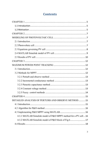
![27
Figure 17: Buck-boost converter circuit
The circuit operation can be divided into 2 modes. During ON mode transistor
Q1 is turned on and diode D is reverse biased. The input current which raises
flows through inductor L and transistor Q1. During OFF mode transistor is
switched off and the current which was flowing through inductor L would flow
through L C D and load as shown below.[6]
Figure1.1: Switch on-mode Figure1.2: switch off-mode](https://image.slidesharecdn.com/fc6b2820-8804-43cc-a594-135634d6b833-160520075343/85/report3-27-320.jpg)
![32
REFERENCES
[1] J.A. Ramos, I. Zamora, J.J. Campayo. “Modeling of Photovoltaic Module”,
International Conference on Renewable Energies and Power Quality (ICREPQ’
10) Granada, Spain, 23-25 March 2010.
[2] Z. M. Salameh, D, Fouad, and A. William, "Step-down maximum power point
tracker for photovoltaic systems," Solar Energy, Vol. 46, No. 5, pp. 279-282,
1991.
[3] Cuauhtemoc Rodriguez, and Gehan A. J Amaratunga, "AnalyticSolution to
the Photovoltaic Maximum Power Point Problem," IEEE Transactions on Circuit
and Systems, Vol. 54, No. 9, pp. 2054–2060, September 2007
[4] J. Nelson, The Physics of Solar Cells. London, U.K.: Imperial College Press,
2003.
[5] Trishan Esram, and Patrick L. Chapman, "Comparison of Photovoltaic Array
Maximum Power Point Tracking Techniques," IEEE Transactions on Energy
Conversion, vol. 22, No. 2, pp. 439-449, June. 2007.
[6] Mummadi Veerachary, Tomonobu Senjyu, and Katsumi Uezato,
"Feedforward Maximum Power Point Tracking of PV Systems Using Fuzzy
Controller," IEEE Transactions on Aerospace and Electronic System, Vol. 38, No.
3, pp. 969-981, July 2002
[7] M.Godoy Simoes, and N.N.Franceschetti, "Fuzzy optimisation based control
of a solar array system," IEEE Proc.-Electr. Power Appl., Vol.46, No. 5, pp.552-
558, Sepetember 1999.
[8] Tsai-Fu Wu, Chien-Hsuan Chang, and Yu-Kai Chen, "A Fuzzy-Logic-Controlled
Single-Stage Converter for PV-Powered Lighting System Application," IEEE
Transactions on Industrial Electronics, Vol. 47, No.2, pp.287-296, April 2000.
[9] Mummadi Veerachary, Tomonobu Senjyu, and Katsumi Uezato,"Neural-
Network-Based Maximum-Power-Point Tracking of Coupled-Inductor
Interleaved-Boost-Converter-Supplied PV System Using Fuzzy Controller," IEEE
Transactions on Induetrial Electronics, Vol. 50, No. 4, pp.749-758, August 2003.](https://image.slidesharecdn.com/fc6b2820-8804-43cc-a594-135634d6b833-160520075343/85/report3-32-320.jpg)


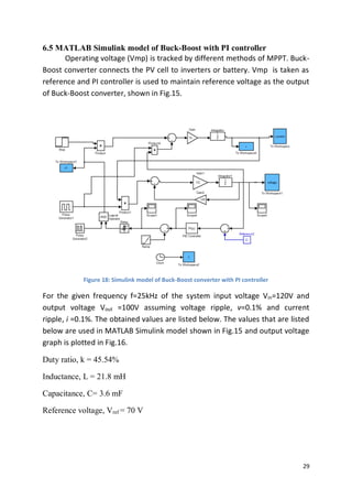
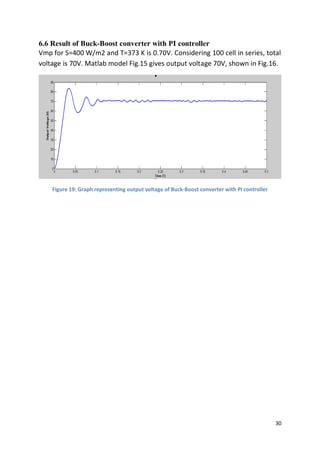
This document describes modeling and maximum power point tracking (MPPT) algorithms for photovoltaic (PV) cells. It presents: 1) A MATLAB/Simulink model of a PV cell that simulates the cell's output power, voltage and current based on solar irradiance and temperature inputs. 2) Two MPPT algorithms - Perturb and Observe (P&O) and a fuzzy logic method - to track the maximum power point of the PV cell as environmental conditions change. 3) A comparison of the tracking times for the P&O and fuzzy logic MPPT methods, showing the fuzzy logic technique produces a more stable power output.