MPPT using P&O method and ANN method in solar PV array
This document presents a comparative study of maximum power point tracking (MPPT) techniques in solar photovoltaic arrays using the Perturb and Observe (P&O) method and Artificial Neural Network (ANN) method. The study reveals that while the P&O method suffers from oscillations in steady states, the ANN method provides a more stable and efficient tracking of maximum power. The authors aim to develop models, simulate performance under identical conditions, and highlight the advantages of the ANN method over the P&O method.
MPPT using P&O method and ANN method in solar PV array
1.
A COMPARATIVE STUDYOF MAXIMUM POWER
POINT TRACKING (MPPT) USING P&O METHOD
AND ANN METHOD IN SOLAR PV ARRAY
SUBRAT KUMAR DASH
SIDHARTH PANIGRAHI
SMRUTI SAGAR PATTANAIK
BTECH MAJOR PROJECT PRESENTATION
BY
2.
CONTENTS
Problem statement
Motivation
Objectives
Literature review of all MPPT techniques
Photovoltaic array and characteristics
Need of MPPT and need of boost converter
PV panel circuit with MPPT controller and boost converter
P&O based MPPT algorithm and circuit
ANN based MPPT algorithm and circuit
Results
Conclusion
Future scope
References
10-07-2020 2
3.
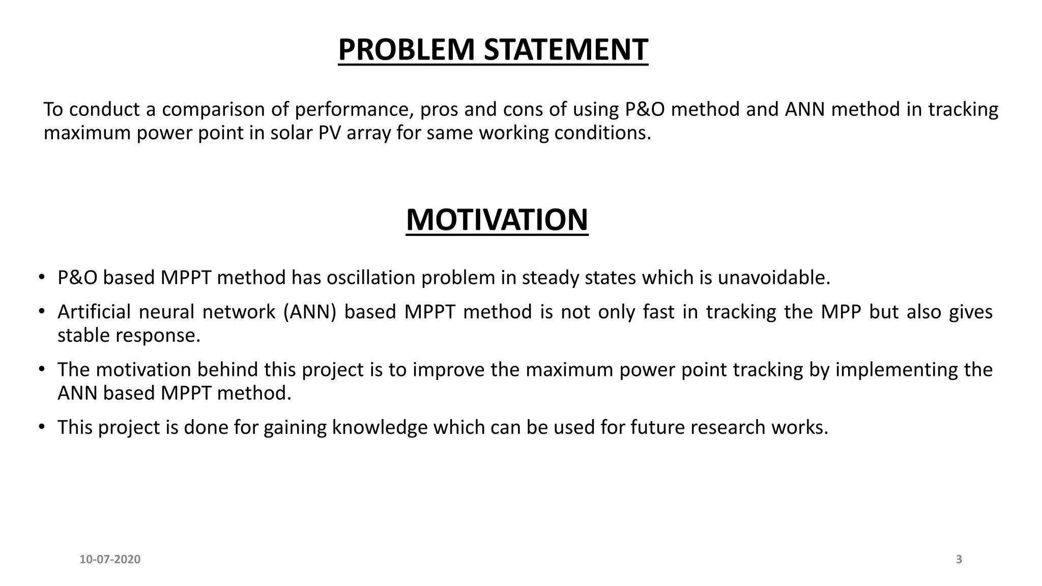
PROBLEM STATEMENT
To conducta comparison of performance, pros and cons of using P&O method and ANN method in tracking
maximum power point in solar PV array for same working conditions.
MOTIVATION
• P&O based MPPT method has oscillation problem in steady states which is unavoidable.
• Artificial neural network (ANN) based MPPT method is not only fast in tracking the MPP but also gives
stable response.
• The motivation behind this project is to improve the maximum power point tracking by implementing the
ANN based MPPT method.
• This project is done for gaining knowledge which can be used for future research works.
10-07-2020 3
4.
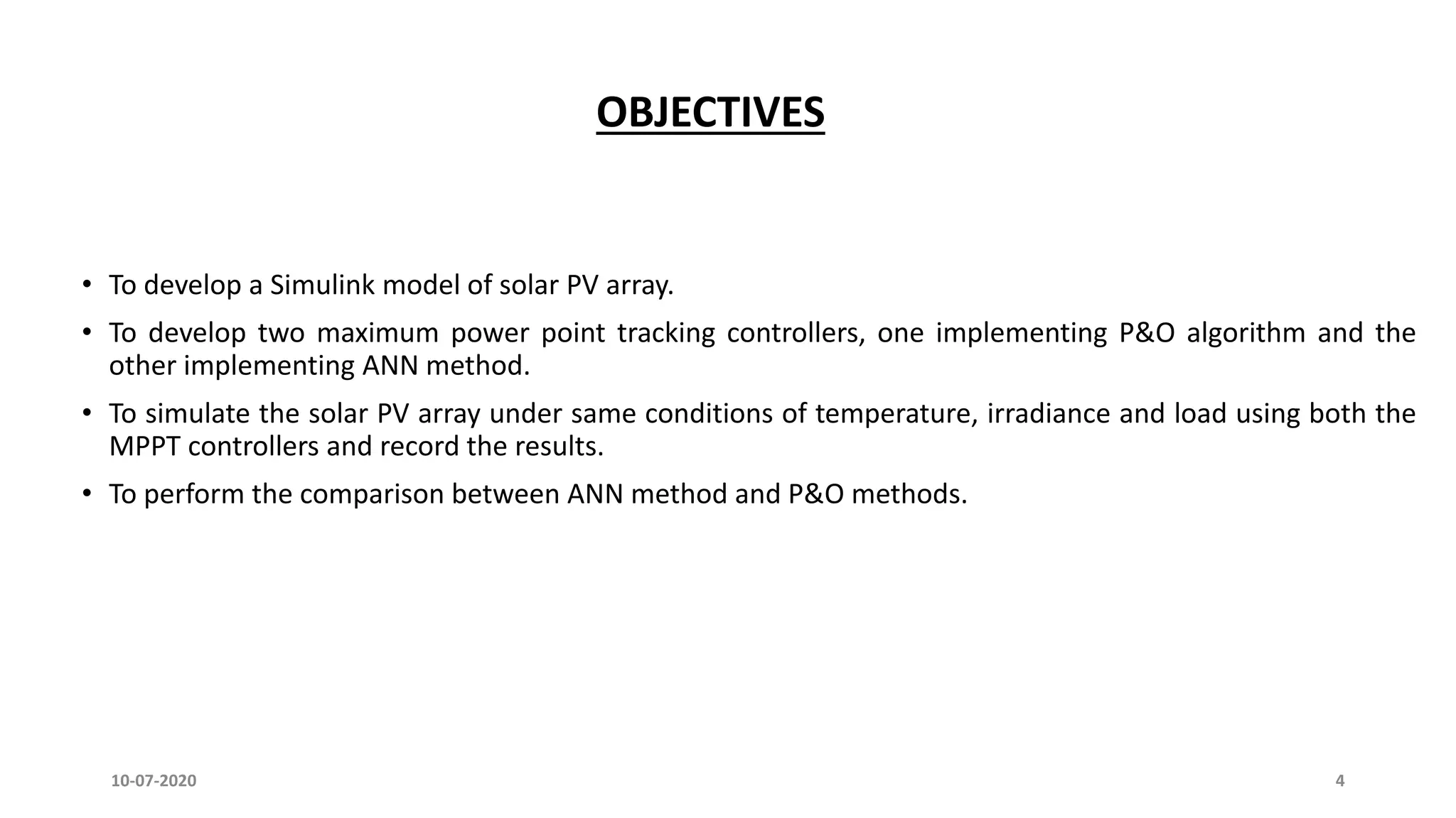
OBJECTIVES
• To developa Simulink model of solar PV array.
• To develop two maximum power point tracking controllers, one implementing P&O algorithm and the
other implementing ANN method.
• To simulate the solar PV array under same conditions of temperature, irradiance and load using both the
MPPT controllers and record the results.
• To perform the comparison between ANN method and P&O methods.
10-07-2020 4
5.
10-07-2020 5
MPPT techniqueAuthors Convergence
speed
Implementation
complexity
Periodic tuning Sensed parameters
Perturb &
observe
S Uma Ramani et al. [1]
and Ali F Murtuza et al. [2]
Varies Low No Voltage
Incremental
conductance
S Uma Ramani et al. [1]
and Ali F Murtuza et al. [2]
Varies Medium No Voltage, current
Fractional Voc Ali F Murtuza et al. [2] Medium Low Yes Voltage
Fractional Isc Ali F Murtuza et al. [2] Medium Medium Yes Current
Fuzzy logic
control
Narendiran. S et al. [4] Fast High Yes Varies
Neural network Jyothy Lakshmi P. N et al.
[3]
Fast High Yes Varies
LITERATURE REVIEW OF ALL MPPT TECHNIQUES
6.
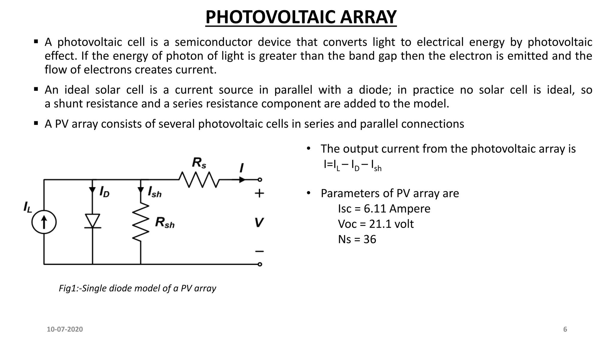
PHOTOVOLTAIC ARRAY
Aphotovoltaic cell is a semiconductor device that converts light to electrical energy by photovoltaic
effect. If the energy of photon of light is greater than the band gap then the electron is emitted and the
flow of electrons creates current.
An ideal solar cell is a current source in parallel with a diode; in practice no solar cell is ideal, so
a shunt resistance and a series resistance component are added to the model.
A PV array consists of several photovoltaic cells in series and parallel connections
• The output current from the photovoltaic array is
I=IL – ID – Ish
Fig1:-Single diode model of a PV array
10-07-2020 6
• Parameters of PV array are
Isc = 6.11 Ampere
Voc = 21.1 volt
Ns = 36
7.
Fig2:- I-V characteristicsof a PV array Fig3:- P-V characteristics curve of PV array
10-07-2020 7
PV ARRAY CHARACTERISTICS
8.
10-07-2020 8
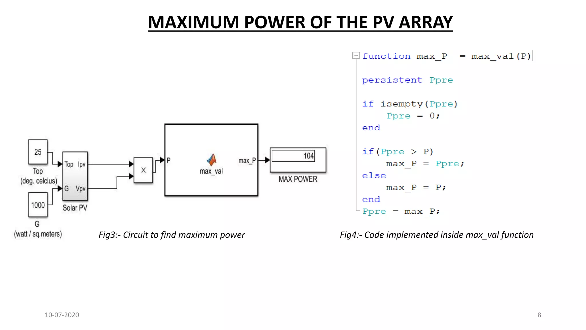
MAXIMUM POWEROF THE PV ARRAY
Fig3:- Circuit to find maximum power Fig4:- Code implemented inside max_val function
9.
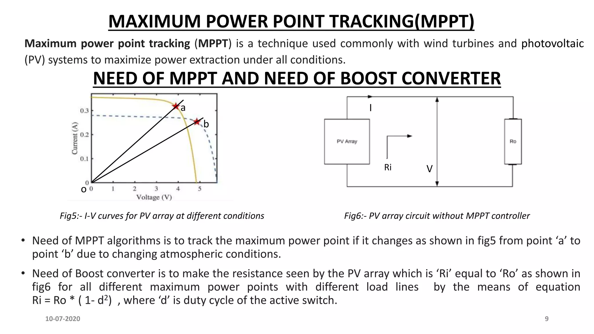
MAXIMUM POWER POINTTRACKING(MPPT)
Maximum power point tracking (MPPT) is a technique used commonly with wind turbines and photovoltaic
(PV) systems to maximize power extraction under all conditions.
NEED OF MPPT AND NEED OF BOOST CONVERTER
a
b
• Need of MPPT algorithms is to track the maximum power point if it changes as shown in fig5 from point ‘a’ to
point ‘b’ due to changing atmospheric conditions.
• Need of Boost converter is to make the resistance seen by the PV array which is ‘Ri’ equal to ‘Ro’ as shown in
fig6 for all different maximum power points with different load lines by the means of equation
Ri = Ro * ( 1- d2) , where ‘d’ is duty cycle of the active switch.
I
Ri V
o
Fig5:- I-V curves for PV array at different conditions Fig6:- PV array circuit without MPPT controller
10-07-2020 9
10.
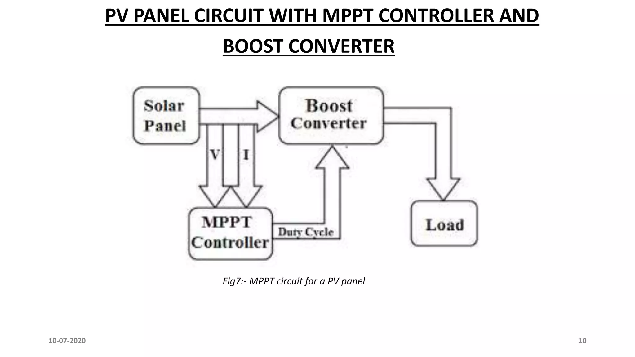
Fig7:- MPPT circuitfor a PV panel
10-07-2020 10
PV PANEL CIRCUIT WITH MPPT CONTROLLER AND
BOOST CONVERTER
11.
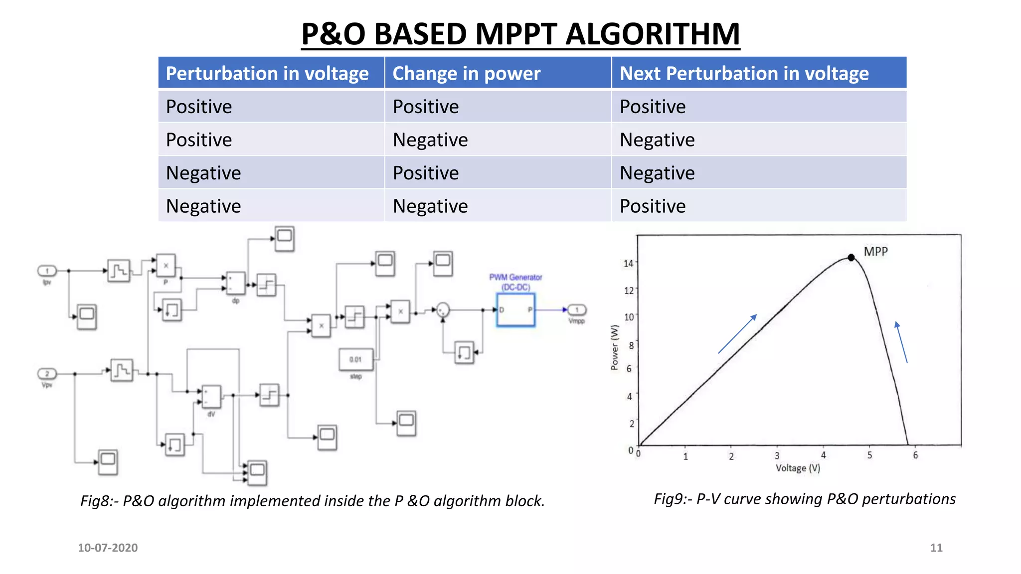
P&O BASED MPPTALGORITHM
Fig9:- P-V curve showing P&O perturbations
10-07-2020 11
Fig8:- P&O algorithm implemented inside the P &O algorithm block.
Perturbation in voltage Change in power Next Perturbation in voltage
Positive Positive Positive
Positive Negative Negative
Negative Positive Negative
Negative Negative Positive
12.
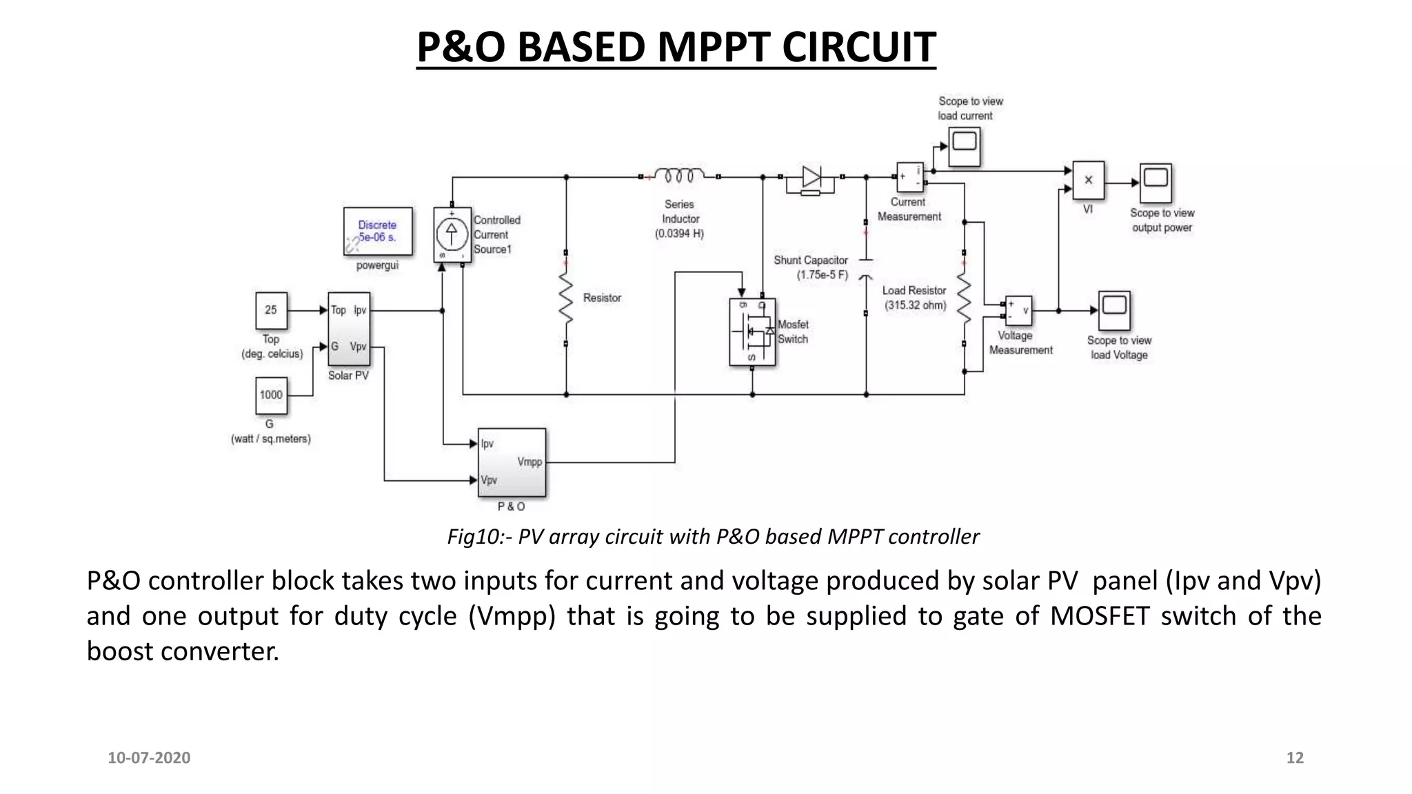
Fig10:- PV arraycircuit with P&O based MPPT controller
P&O controller block takes two inputs for current and voltage produced by solar PV panel (Ipv and Vpv)
and one output for duty cycle (Vmpp) that is going to be supplied to gate of MOSFET switch of the
boost converter.
10-07-2020 12
P&O BASED MPPT CIRCUIT
13.
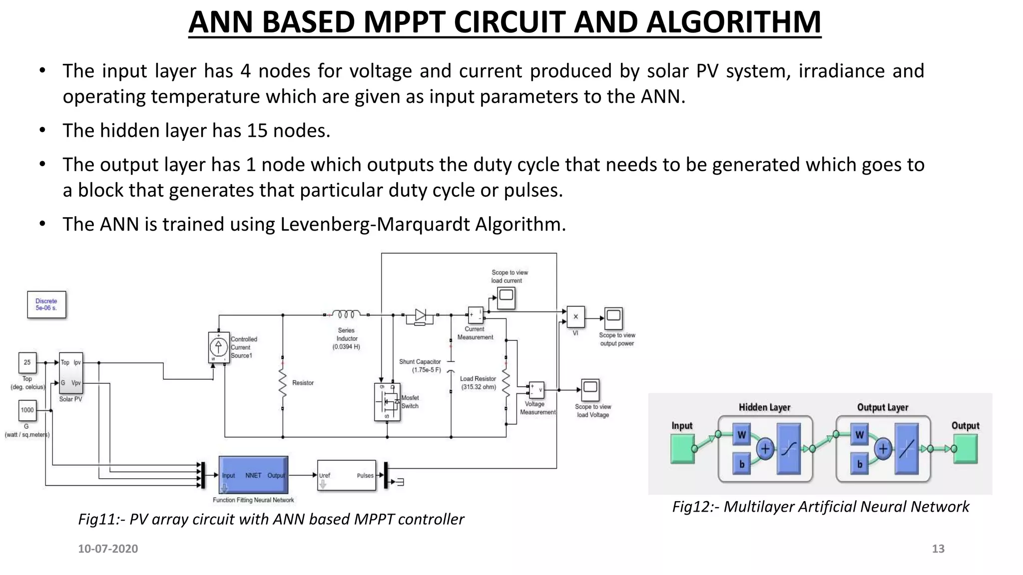
ANN BASED MPPTCIRCUIT AND ALGORITHM
10-07-2020 13
• The input layer has 4 nodes for voltage and current produced by solar PV system, irradiance and
operating temperature which are given as input parameters to the ANN.
• The hidden layer has 15 nodes.
• The output layer has 1 node which outputs the duty cycle that needs to be generated which goes to
a block that generates that particular duty cycle or pulses.
• The ANN is trained using Levenberg-Marquardt Algorithm.
Fig11:- PV array circuit with ANN based MPPT controller
Fig12:- Multilayer Artificial Neural Network
14.
10-07-2020 14
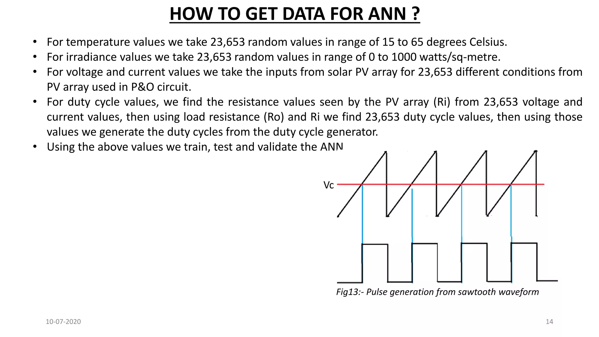
• Fortemperature values we take 23,653 random values in range of 15 to 65 degrees Celsius.
• For irradiance values we take 23,653 random values in range of 0 to 1000 watts/sq-metre.
• For voltage and current values we take the inputs from solar PV array for 23,653 different conditions from
PV array used in P&O circuit.
• For duty cycle values, we find the resistance values seen by the PV array (Ri) from 23,653 voltage and
current values, then using load resistance (Ro) and Ri we find 23,653 duty cycle values, then using those
values we generate the duty cycles from the duty cycle generator.
• Using the above values we train, test and validate the ANN
HOW TO GET DATA FOR ANN ?
Fig13:- Pulse generation from sawtooth waveform
Vc
15.
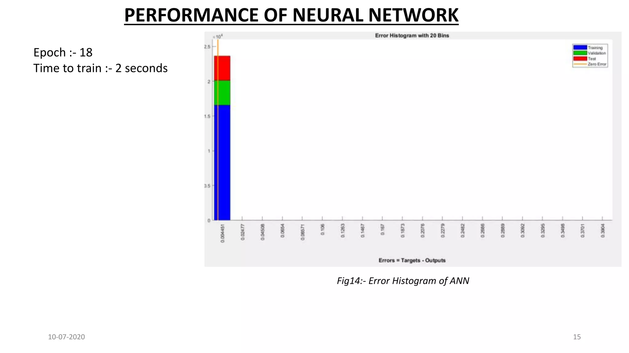
10-07-2020 15
Fig14:- ErrorHistogram of ANN
PERFORMANCE OF NEURAL NETWORK
Epoch :- 18
Time to train :- 2 seconds
16.
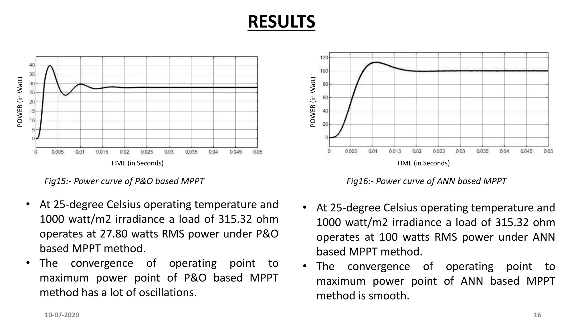
Fig15:- Power curveof P&O based MPPT Fig16:- Power curve of ANN based MPPT
RESULTSPOWER(inWatt)
TIME (in Seconds)
POWER(inWatt)
TIME (in Seconds)
• At 25-degree Celsius operating temperature and
1000 watt/m2 irradiance a load of 315.32 ohm
operates at 100 watts RMS power under ANN
based MPPT method.
• The convergence of operating point to
maximum power point of ANN based MPPT
method is smooth.
• At 25-degree Celsius operating temperature and
1000 watt/m2 irradiance a load of 315.32 ohm
operates at 27.80 watts RMS power under P&O
based MPPT method.
• The convergence of operating point to
maximum power point of P&O based MPPT
method has a lot of oscillations.
10-07-2020 16
17.
CONCLUSION
In this projectit is observed that ANN based MPPT method is more efficient than P&O based MPPT method in
tracking maximum power under same working conditions.
P&O method oscillates about maximum power point and never actually converges to a single point but ANN
method converges to a single point. The oscillations about maximum power point in case of P&O method may
be reduced by decreasing the perturbation size but it will also delay the tracking process.
ANN based MPPT has a more complex software implementation than P&O based MPPT.
ANN based MPPT has constant convergence speed but P&O based MPPT can have variable convergence speed
due to step size variation.
10-07-2020 17
18.
FUTURE SCOPE
In thisproject the ANN is trained offline that is when it is not implemented in the MPPT circuit. But if the ANN
can be made to train on newer data sets while still being online and being used in MPPT circuit then it will be
helpful and time saving.
10-07-2020 18
19.
REFERENCES
[1] S UmaRamani, Satish Kumar Kollimalla, B. Arundhati, “Comparative study of P & O and Incremental
Conductance method for PV System”, 2017 International Conference on Circuit, Power & Computing
Technologies (ICCPCT).
[2] Ali F Murtuza, Hadeed Ahmed Cher, Marcello Chiaberge, Diego Boero, Mirko De Giaseppe, Khaled E
Addoweesh, “Comparative Analysis of Maximum Power Point Tracking Techniques for PV applications”,
2013, INMIC.
[3] Jyothy Lakshmi P. N, M.R Sindhu, “An Artificial Neural Network based MPPT Algorithm for Solar PV System”,
2018 4th International Conference on Electrical Energy Systems (ICEES).
[4] Narendiran. S, Sarat Kumar Sahoo, Raja Das, Ashwin Kumar Sahoo, “Fuzzy logic based Maximum power
point tracking for PV System”, 2016 3rd International Conference on Electrical Systems (ICEES).
[5] Salmi T, Bouzguenda M, Gastli A, Masmoudi A, "MATLAB/simulink based modelling of solar photovoltaic
cell“, 2012 Int J Renew Energy Res 2(2):6
10-07-2020 19
[6] Motahhir, S., Ghzizal, A. E., Sebti, S., & Derouich, A,“Proposal and implementation of a novel perturb and
observe algorithm using embedded software”, 2015 3rd International Renewable and Sustainable Energy
Conference (IRSEC)
![10-07-2020 5
MPPT technique Authors Convergence
speed
Implementation
complexity
Periodic tuning Sensed parameters
Perturb &
observe
S Uma Ramani et al. [1]
and Ali F Murtuza et al. [2]
Varies Low No Voltage
Incremental
conductance
S Uma Ramani et al. [1]
and Ali F Murtuza et al. [2]
Varies Medium No Voltage, current
Fractional Voc Ali F Murtuza et al. [2] Medium Low Yes Voltage
Fractional Isc Ali F Murtuza et al. [2] Medium Medium Yes Current
Fuzzy logic
control
Narendiran. S et al. [4] Fast High Yes Varies
Neural network Jyothy Lakshmi P. N et al.
[3]
Fast High Yes Varies
LITERATURE REVIEW OF ALL MPPT TECHNIQUES](https://image.slidesharecdn.com/acomparativestudyofmaximumpowerpointtrackingmpptusingpomethodandannmethodinsolarpvarray-200710063244/75/MPPT-using-P-O-method-and-ANN-method-in-solar-PV-array-5-2048.jpg)

![REFERENCES
[1] S Uma Ramani, Satish Kumar Kollimalla, B. Arundhati, “Comparative study of P & O and Incremental
Conductance method for PV System”, 2017 International Conference on Circuit, Power & Computing
Technologies (ICCPCT).
[2] Ali F Murtuza, Hadeed Ahmed Cher, Marcello Chiaberge, Diego Boero, Mirko De Giaseppe, Khaled E
Addoweesh, “Comparative Analysis of Maximum Power Point Tracking Techniques for PV applications”,
2013, INMIC.
[3] Jyothy Lakshmi P. N, M.R Sindhu, “An Artificial Neural Network based MPPT Algorithm for Solar PV System”,
2018 4th International Conference on Electrical Energy Systems (ICEES).
[4] Narendiran. S, Sarat Kumar Sahoo, Raja Das, Ashwin Kumar Sahoo, “Fuzzy logic based Maximum power
point tracking for PV System”, 2016 3rd International Conference on Electrical Systems (ICEES).
[5] Salmi T, Bouzguenda M, Gastli A, Masmoudi A, "MATLAB/simulink based modelling of solar photovoltaic
cell“, 2012 Int J Renew Energy Res 2(2):6
10-07-2020 19
[6] Motahhir, S., Ghzizal, A. E., Sebti, S., & Derouich, A,“Proposal and implementation of a novel perturb and
observe algorithm using embedded software”, 2015 3rd International Renewable and Sustainable Energy
Conference (IRSEC)](https://image.slidesharecdn.com/acomparativestudyofmaximumpowerpointtrackingmpptusingpomethodandannmethodinsolarpvarray-200710063244/75/MPPT-using-P-O-method-and-ANN-method-in-solar-PV-array-19-2048.jpg)