Downloaded 77 times


The document discusses infrared and thermal testing, explaining the concept of infrared radiation and its historical development, including key figures such as Sir William Herschel. It details the principles and techniques of thermography as a non-contact predictive maintenance strategy used for inspecting mechanical and electrical systems. The application of infrared technology in various electrical and mechanical equipment is emphasized, along with factors affecting infrared detection and analysis.
Introduction to using infrared and thermal testing for detecting mechanical and electrical system abnormalities.
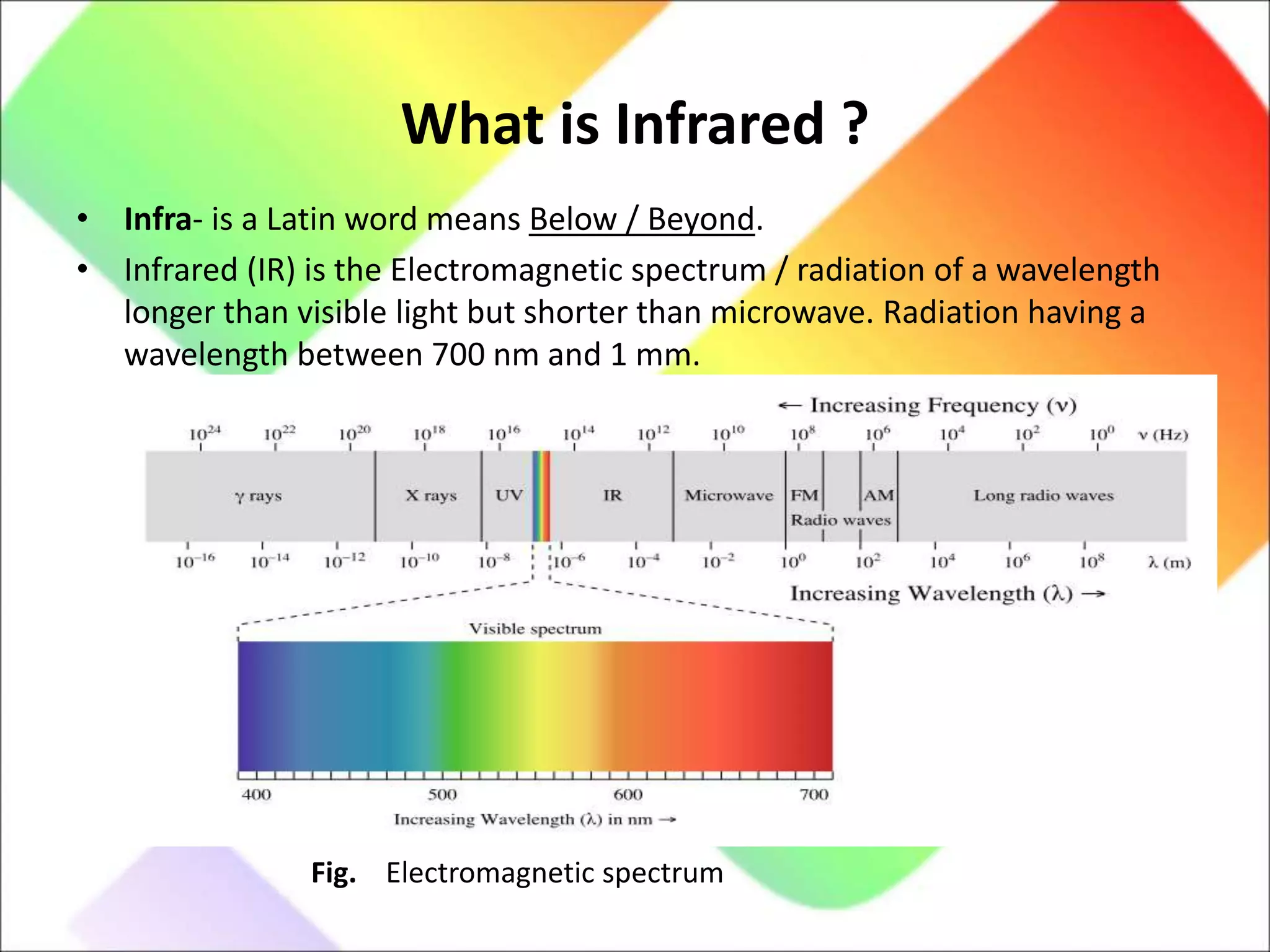
Definition of Infrared (IR) as electromagnetic radiation between 700 nm and 1 mm, beyond visible light.
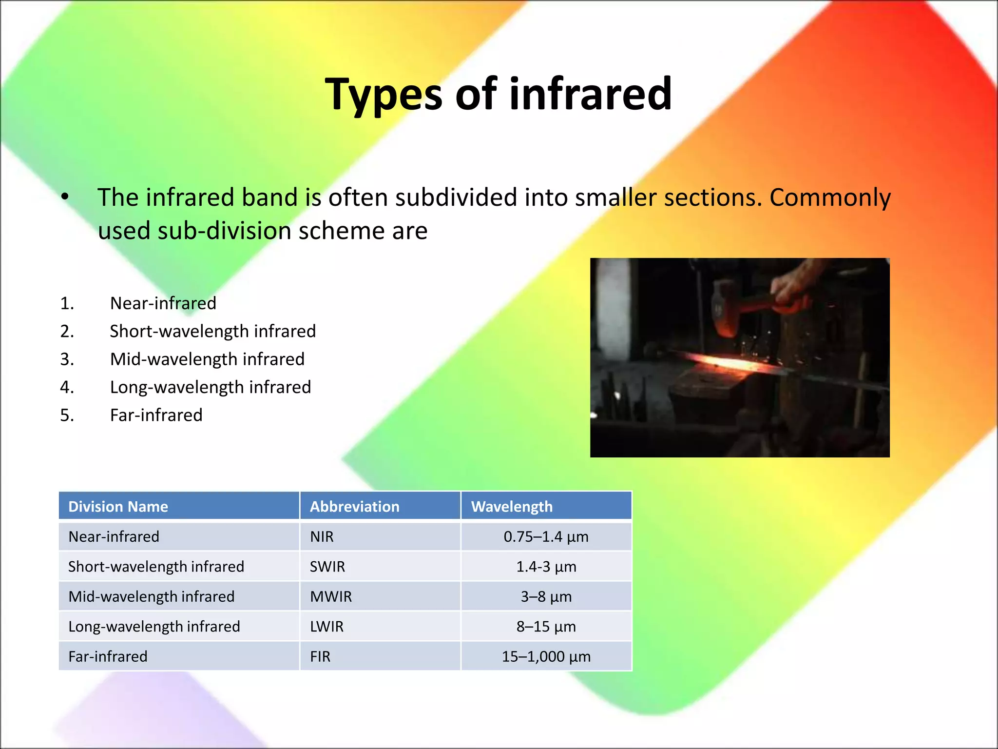
Different subdivisions of infrared: Near, Short, Mid, Long, and Far-infrared with specific wavelength ranges.
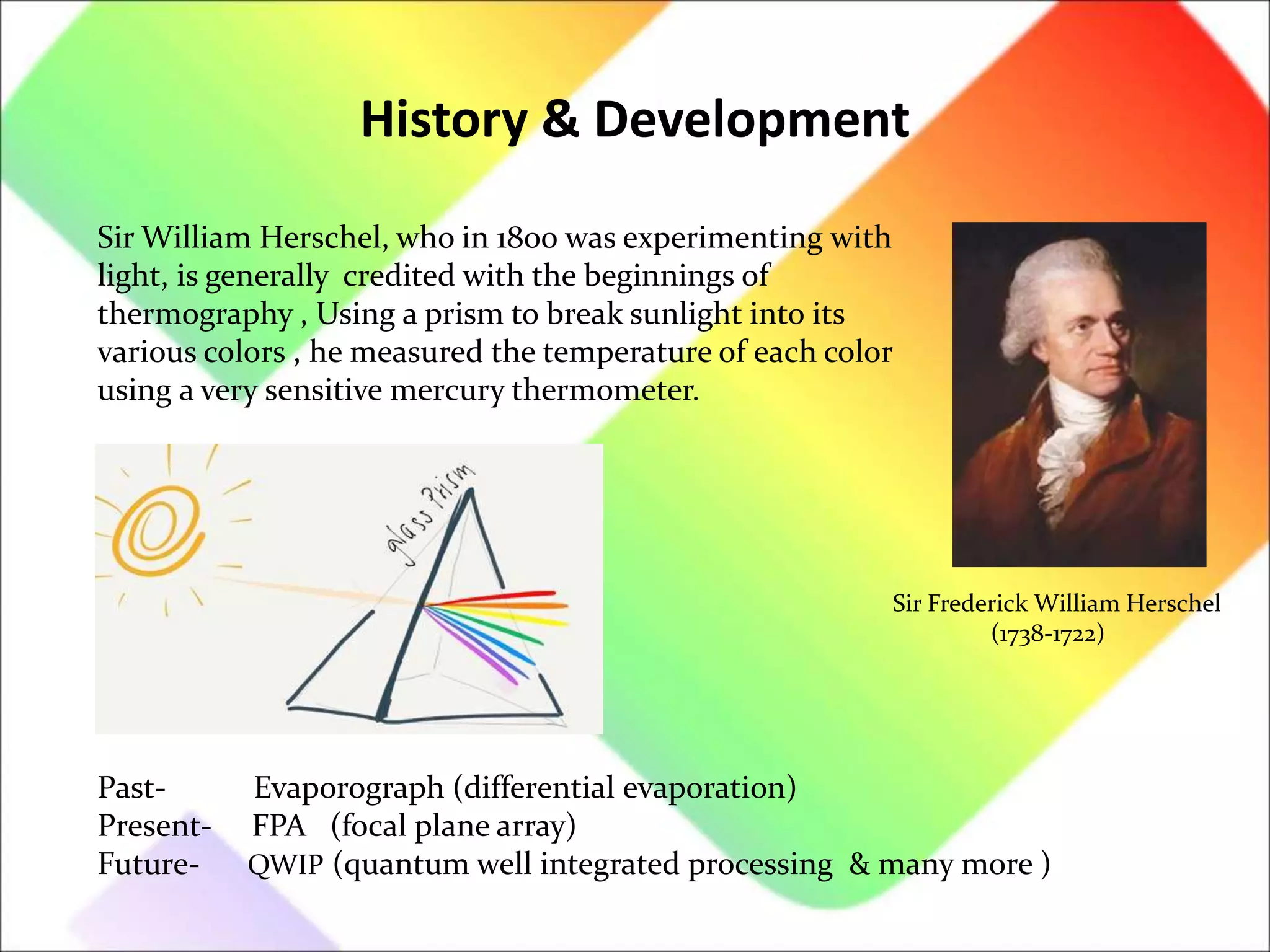
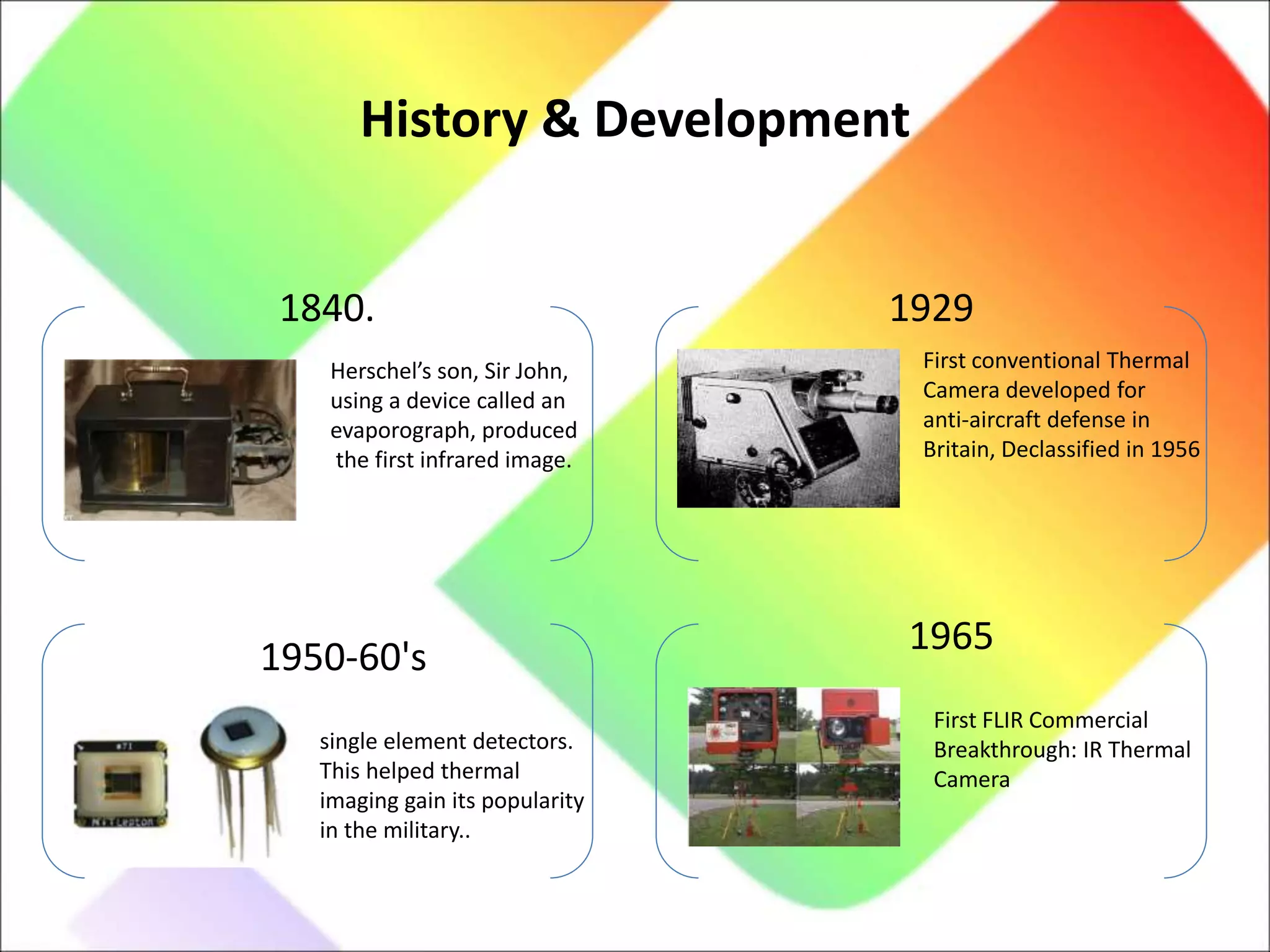
Historical milestones in thermography development, starting with Sir William Herschel's experiments to the first infrared images.
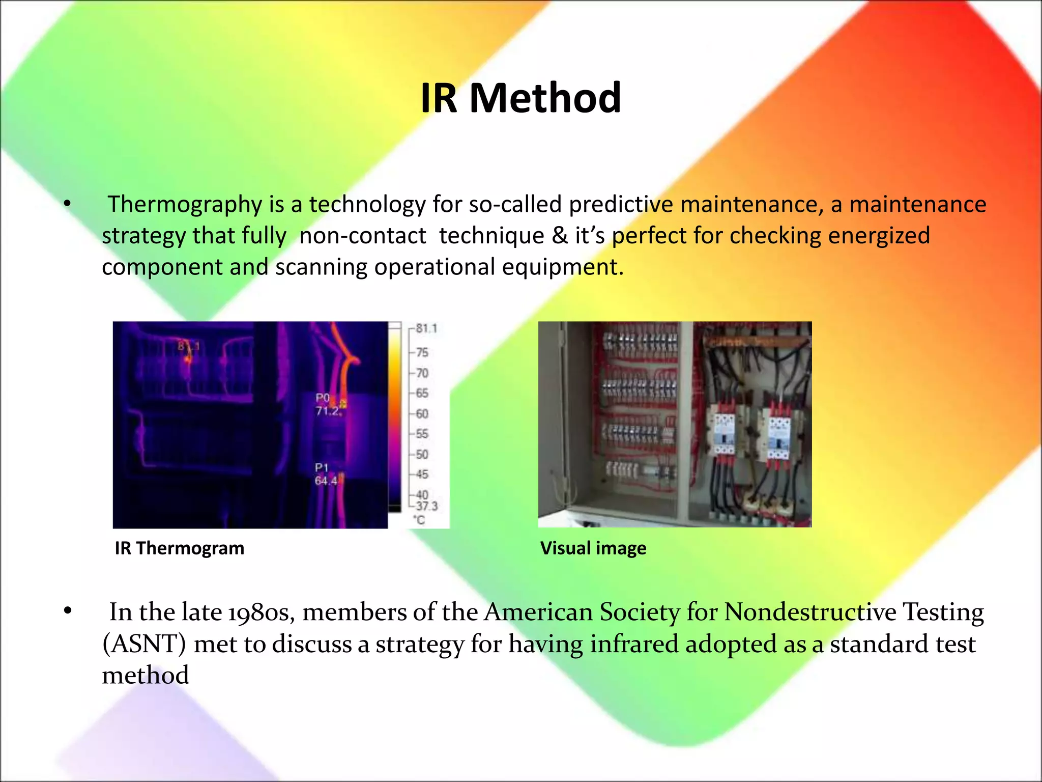
Infrared radiation detection as a non-visible energy form; its role in predictive maintenance through thermography.
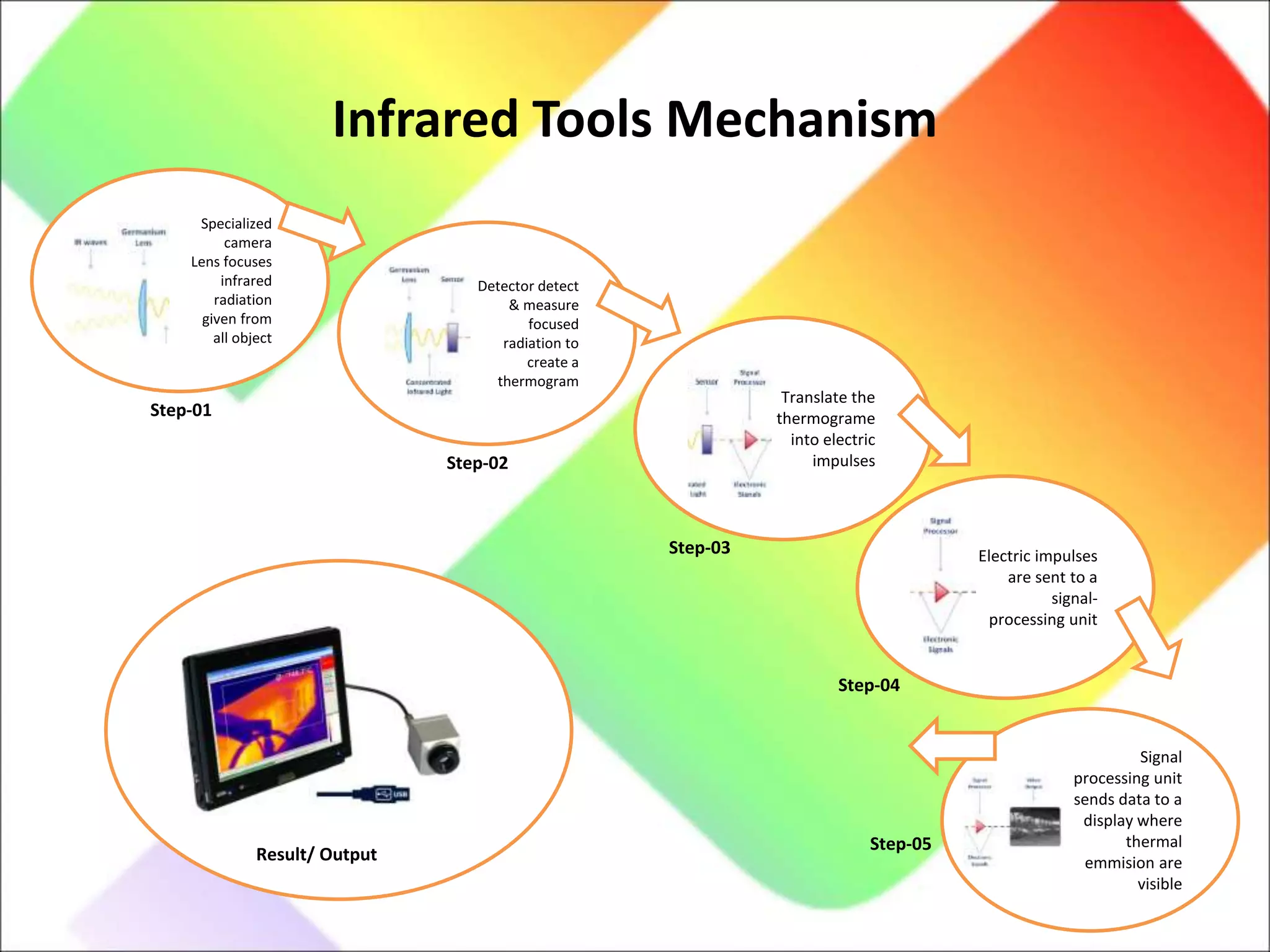
Description of infrared camera functions, from lens focusing to signal processing for thermogram creation.
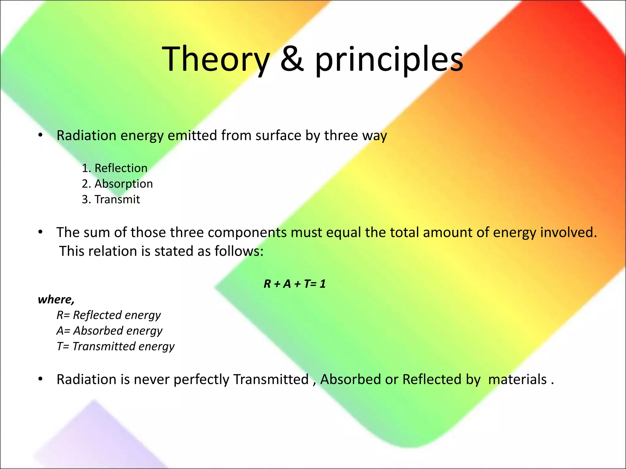
Modes of heat transfer: conduction, convection, radiation, and the energy relationships involving reflection, absorption, and transmission.
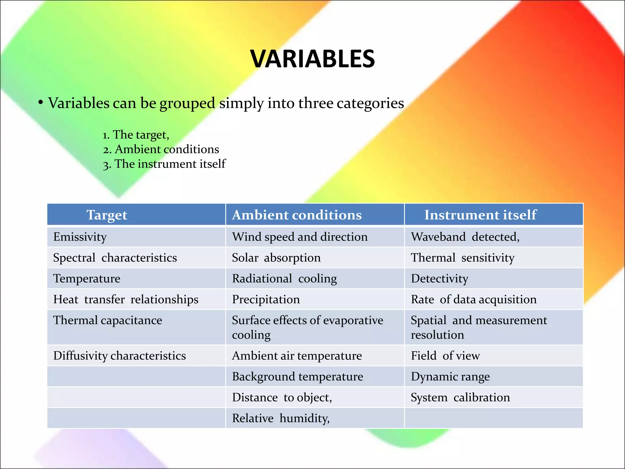
Categories of variables affecting infrared measurements: target properties, ambient conditions, and instrument characteristics.
Common emissivity values for different materials, crucial for accurate thermal measurement.
Comparative thermography strategy for assessing thermal images by comparing with baseline equipment performance.
Overview of the infrared inspection process, emphasizing the methodology.
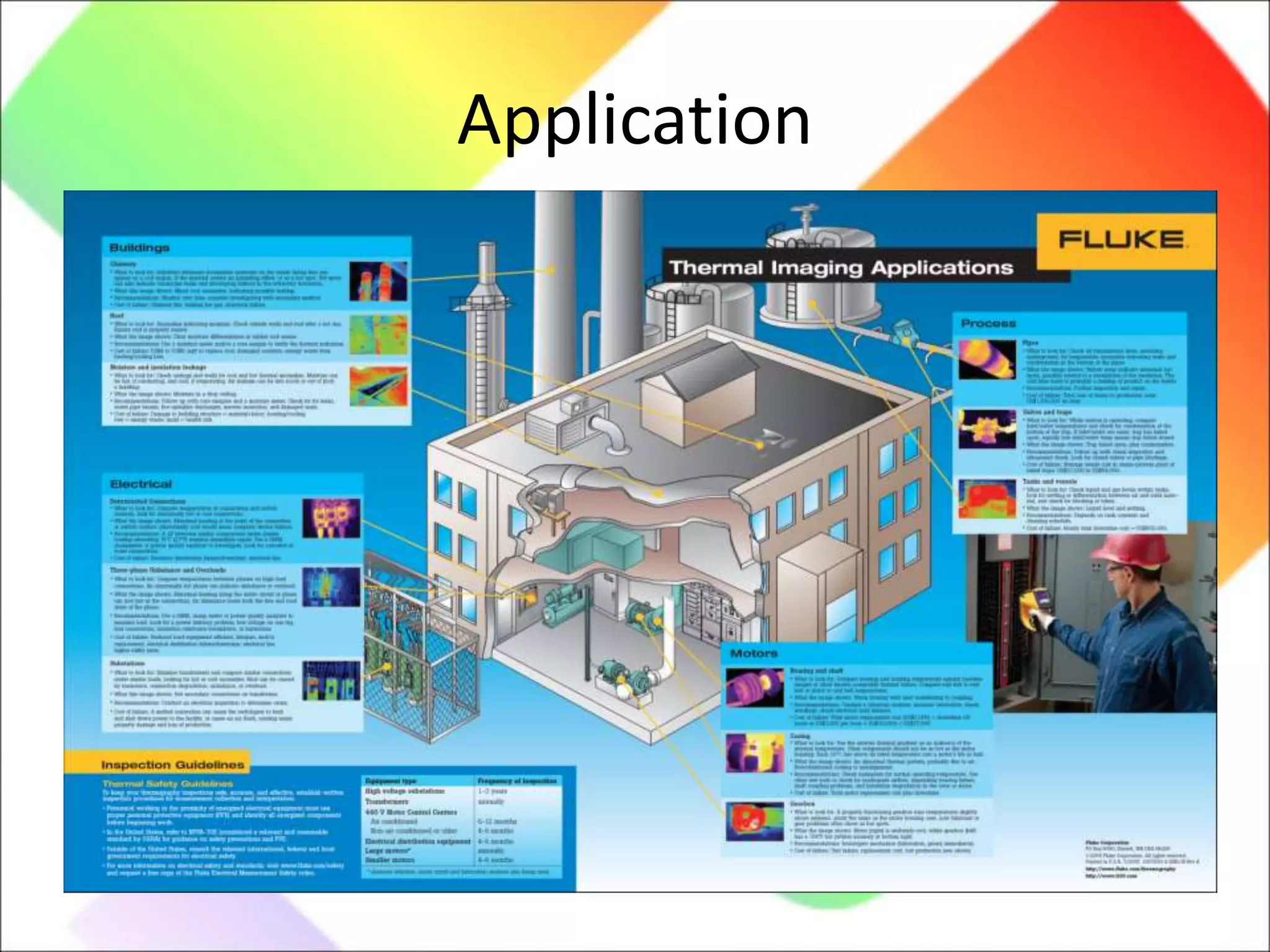
Diverse applications of thermography across electrical and mechanical equipment, detailing various components and maintenance contexts.


