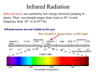
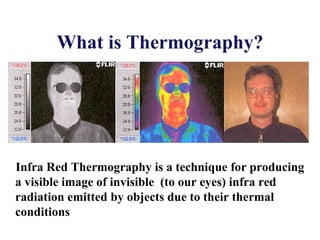
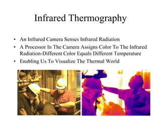
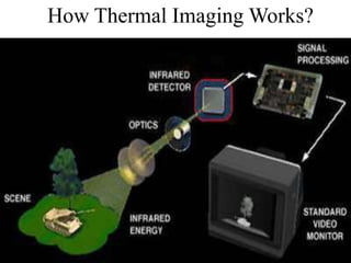
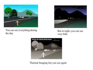
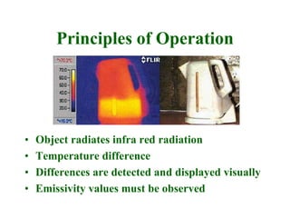
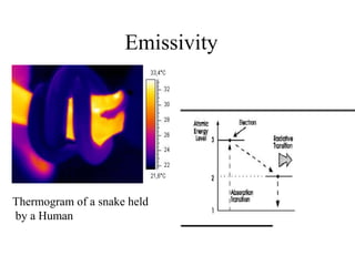
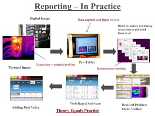
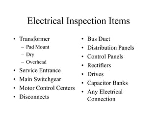
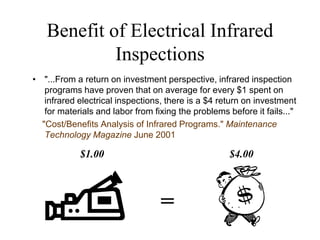
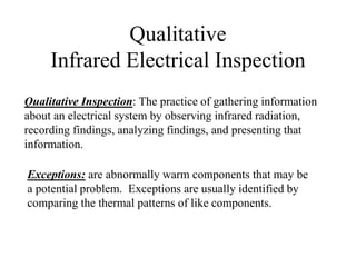
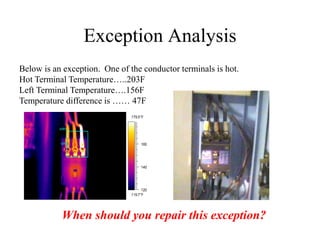
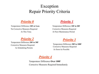
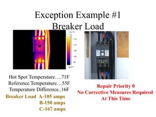
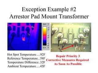
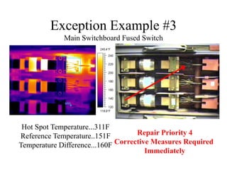
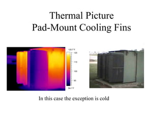
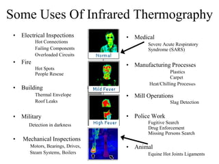
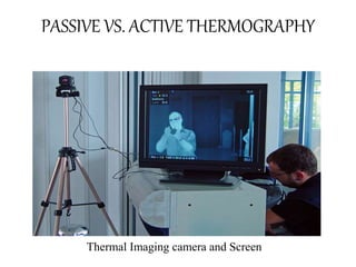
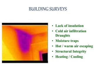
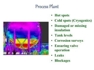
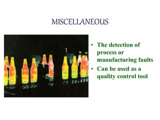
Submitted By
S.MOUNIKA
G.MADHULIKA
(4/4ece)
gitam univerity
THERMAL IMAGING
Infrared Radiation
Wavelength is longer than visible light.
Infrared waves are not visible to the eye
Infra red waves are emitted by low energy electrons jumping in
atoms. Their wavelength ranges from 1mm to 10-7 m and
frequency from 1011 to 4x10¹⁴ Hz.
What is Thermography?
Infra Red Thermography is a technique for producing
a visible image of invisible (to our eyes) infra red
radiation emitted by objects due to their thermal
conditions
Infrared Thermography
• An Infrared Camera Senses Infrared Radiation
• A Processor In The Camera Assigns Color To The Infrared
Radiation-Different Color Equals Different Temperature
• Enabling Us To Visualize The Thermal World
Why Thermography?
• Non Contact
• Rapid Scanning
• Data can be recorded in differing formats
• Images produced are comprehensive &
reliable
Test Equipment
• Hand held portable camera
• Battery Powered
• Operating at correct
wavelength
• Range…..-20°c to +1500°c
• Sensitivity…..0.1°c at 30°c
• Real time display
• Image Recording capability
Construction
A handheld thermal imaging camera
Usage
View of a fire apparatus tire through a thermal imaging camera
How Thermal Imaging Works?
You can see everything during
the day
But at night, you can see
very little
Thermal Imaging lets you see again
Principles of Operation
• Object radiates infra red radiation
• Temperature difference
• Differences are detected and displayed visually
• Emissivity values must be observed
E
Emissivity
Thermogram of a snake held
by a Human
Reporting – In Practice
Digital Image
Thermal Image
Excess heat = potential problem
Data capture and input on site
Pen Tablet
Instantaneous reporting
Build Inventory list during
inspection or pre-load
from excel
Web-Based Software Detailed Problem
IdentificationAdding Real Value
Theory Equals Practice
Electrical Inspection Items
• Transformer
– Pad Mount
– Dry
– Overhead
• Service Entrance
• Main Switchgear
• Motor Control Centers
• Disconnects
• Bus Duct
• Distribution Panels
• Control Panels
• Rectifiers
• Drives
• Capacitor Banks
• Any Electrical
Connection
Benefits of Periodic
Electrical Infrared Inspections
• Predictive Maintenance...Allows Scheduling Of
Repairs, Forward Buying
• Reduces Downtime… Find It, Repair It, Before It Blows Up
and Stops Production
Benefit of Electrical Infrared
Inspections
• "...From a return on investment perspective, infrared inspection
programs have proven that on average for every $1 spent on
infrared electrical inspections, there is a $4 return on investment
for materials and labor from fixing the problems before it fails..."
"Cost/Benefits Analysis of Infrared Programs." Maintenance
Technology Magazine June 2001
=
$1.00 $4.00
Qualitative
Infrared Electrical Inspection
Exceptions: are abnormally warm components that may be
a potential problem. Exceptions are usually identified by
comparing the thermal patterns of like components.
Qualitative Inspection: The practice of gathering information
about an electrical system by observing infrared radiation,
recording findings, analyzing findings, and presenting that
information.
Exception Analysis
Below is an exception. One of the conductor terminals is hot.
Hot Terminal Temperature…..203F
Left Terminal Temperature….156F
Temperature difference is …… 47F
119.7°F
179.5°F
120
140
160
AR01
SP01
When should you repair this exception?
Exception
Repair Priority Criteria
Priority 0
Temperature Difference 10F or Less
No Corrective Measures Required
At This Time.
Priority 4
Temperature Difference Over 100F
Corrective Measures Required Immediately
Priority 3
Temperature Difference 30F to 100F
Corrective Measures Required
As Soon As Possible
Priority 2
Temperature Difference 20F to 30F
Corrective Measures Required
As Scheduling Permits
Priority 1
Temperature Difference 10F to 20F
Corrective Measures Required
At Next Maintenance Period
Exception Example #1
Breaker Load
Hot Spot Temperature….71F
Reference Temperature…55F
Temperature Difference..16F
Repair Priority 0
No Corrective Measures Required
At This Time
92.6°F
119.1°F
95
100
105
110
115
Breaker Load A-105 amps
B-150 amps
C-167 amps
Exception Example #2
Arrestor Pad Mount Transformer
Hot Spot Temperature….92F
Reference Temperature...58F
Temperature Difference..32F
Ambient Temperature….45F
Repair Priority 3
Corrective Measures Required
As Soon As Possible
Exception Example #3
Main Switchboard Fused Switch
Hot Spot Temperature...311F
Reference Temperature..151F
Temperature Difference...160F
Repair Priority 4
Corrective Measures Required
Immediately
118.9°F
245.4°F
120
140
160
180
200
220
240AR01
SP01
Thermal Picture
Pad-Mount Cooling Fins
In this case the exception is cold
84.1°F
120.7°F
90
100
110
120
Some Uses Of Infrared Thermography
• Electrical Inspections
Hot Connections
Failing Components
Overloaded Circuits
• Fire
Hot Spots
People Rescue
• Building
Thermal Envelope
Roof Leaks
• Military
Detection in darkness
• Mechanical Inspections
Motors, Bearings, Drives,
Steam Systems, Boilers
• Medical
Severe Acute Respiratory
Syndrome (SARS)
• Manufacturing Processes
Plastics
Carpet
Heat/Chilling Processes
• Mill Operations
Slag Detection
• Police Work
Fugitive Search
Drug Enforcement
Missing Persons Search
• Animal
Equine Hot Joints Ligaments
PASSIVE VS. ACTIVE THERMOGRAPHY
Thermal Imaging camera and Screen
Advantages
• Non Contact
• Non Intrusive
• Can work at a distance
• Fast and Reliable
• Portable
• Convincing Results
TRANSFORMERS
• Electrical connections
• Insulators
• Thermal profile
• Operating
temperature
• Liquid Level
ELECTRICAL CONNECTIONS
Used for the detection of;
• Corroded connections
• Slack / loose connectors
• Connectors at too high an
operating temperature
• Hot spots
REFRACTORY LININGS
• Torpedo ladles
• Boilers
• Furnaces
• Exhausts
• Ducting
• Kilns
BUILDING SURVEYS
• Lack of insulation
• Cold air infiltration
Draughts
• Moisture traps
• Hot / warm air escaping
• Structural Integrity
• Heating / Cooling
Process Plant
• Hot spots
• Cold spots (Cryogenics)
• Damaged or missing
insulation
• Tank levels
• Corrosion surveys
• Ensuring valve
operation
• Leaks
• Blockages
MISCELLANEOUS
• The detection of
process or
manufacturing faults
• Can be used as a
quality control tool
LIMITATIONS
• Non Intrinsically safe
• There must be a temperature difference for
certain surveys
• Operator experience is essential
• Filters may be needed for certain
applications
• Only able to detect directly surface
temperatures
ACKNOWLEDGEMENT
On preparing this presentation on “E-NOSE” we
have gained quite some knowledge on this topic
which we were unaware of before. We found it
quite interesting and would like to explore more
about it in the future.
1. Infrared Spectroscopy Fundamentals and Applications- Barbara
Stuart John Wiley and Sons Ltd, Wiley Publications
2. Practical Applications of Infrared Techniques –Ricardo Venzetti
3. Thermal Imaging Techniques-P.E.Glaser
4. Breckon, T.; Gaszczak, A., Han, J., (2011). "Real-time People and
Vehicle Detection from UAV Imagery". Proc. SPIE Conference
Intelligent Robots and Computer Vision XXVIII: Algorithms and
Techniques 7878. doi:10.1117/12.876663
Thank You

THERMAL IMAGING

  • 1.
  • 2.
    Infrared Radiation Wavelength islonger than visible light. Infrared waves are not visible to the eye Infra red waves are emitted by low energy electrons jumping in atoms. Their wavelength ranges from 1mm to 10-7 m and frequency from 1011 to 4x10¹⁴ Hz.
  • 3.
    What is Thermography? InfraRed Thermography is a technique for producing a visible image of invisible (to our eyes) infra red radiation emitted by objects due to their thermal conditions
  • 4.
    Infrared Thermography • AnInfrared Camera Senses Infrared Radiation • A Processor In The Camera Assigns Color To The Infrared Radiation-Different Color Equals Different Temperature • Enabling Us To Visualize The Thermal World
  • 5.
    Why Thermography? • NonContact • Rapid Scanning • Data can be recorded in differing formats • Images produced are comprehensive & reliable
  • 6.
    Test Equipment • Handheld portable camera • Battery Powered • Operating at correct wavelength • Range…..-20°c to +1500°c • Sensitivity…..0.1°c at 30°c • Real time display • Image Recording capability
  • 7.
  • 8.
    Usage View of afire apparatus tire through a thermal imaging camera
  • 9.
  • 10.
    You can seeeverything during the day But at night, you can see very little Thermal Imaging lets you see again
  • 11.
    Principles of Operation •Object radiates infra red radiation • Temperature difference • Differences are detected and displayed visually • Emissivity values must be observed
  • 12.
    E Emissivity Thermogram of asnake held by a Human
  • 13.
    Reporting – InPractice Digital Image Thermal Image Excess heat = potential problem Data capture and input on site Pen Tablet Instantaneous reporting Build Inventory list during inspection or pre-load from excel Web-Based Software Detailed Problem IdentificationAdding Real Value Theory Equals Practice
  • 14.
    Electrical Inspection Items •Transformer – Pad Mount – Dry – Overhead • Service Entrance • Main Switchgear • Motor Control Centers • Disconnects • Bus Duct • Distribution Panels • Control Panels • Rectifiers • Drives • Capacitor Banks • Any Electrical Connection
  • 15.
    Benefits of Periodic ElectricalInfrared Inspections • Predictive Maintenance...Allows Scheduling Of Repairs, Forward Buying • Reduces Downtime… Find It, Repair It, Before It Blows Up and Stops Production
  • 16.
    Benefit of ElectricalInfrared Inspections • "...From a return on investment perspective, infrared inspection programs have proven that on average for every $1 spent on infrared electrical inspections, there is a $4 return on investment for materials and labor from fixing the problems before it fails..." "Cost/Benefits Analysis of Infrared Programs." Maintenance Technology Magazine June 2001 = $1.00 $4.00
  • 17.
    Qualitative Infrared Electrical Inspection Exceptions:are abnormally warm components that may be a potential problem. Exceptions are usually identified by comparing the thermal patterns of like components. Qualitative Inspection: The practice of gathering information about an electrical system by observing infrared radiation, recording findings, analyzing findings, and presenting that information.
  • 18.
    Exception Analysis Below isan exception. One of the conductor terminals is hot. Hot Terminal Temperature…..203F Left Terminal Temperature….156F Temperature difference is …… 47F 119.7°F 179.5°F 120 140 160 AR01 SP01 When should you repair this exception?
  • 19.
    Exception Repair Priority Criteria Priority0 Temperature Difference 10F or Less No Corrective Measures Required At This Time. Priority 4 Temperature Difference Over 100F Corrective Measures Required Immediately Priority 3 Temperature Difference 30F to 100F Corrective Measures Required As Soon As Possible Priority 2 Temperature Difference 20F to 30F Corrective Measures Required As Scheduling Permits Priority 1 Temperature Difference 10F to 20F Corrective Measures Required At Next Maintenance Period
  • 20.
    Exception Example #1 BreakerLoad Hot Spot Temperature….71F Reference Temperature…55F Temperature Difference..16F Repair Priority 0 No Corrective Measures Required At This Time 92.6°F 119.1°F 95 100 105 110 115 Breaker Load A-105 amps B-150 amps C-167 amps
  • 21.
    Exception Example #2 ArrestorPad Mount Transformer Hot Spot Temperature….92F Reference Temperature...58F Temperature Difference..32F Ambient Temperature….45F Repair Priority 3 Corrective Measures Required As Soon As Possible
  • 22.
    Exception Example #3 MainSwitchboard Fused Switch Hot Spot Temperature...311F Reference Temperature..151F Temperature Difference...160F Repair Priority 4 Corrective Measures Required Immediately 118.9°F 245.4°F 120 140 160 180 200 220 240AR01 SP01
  • 23.
    Thermal Picture Pad-Mount CoolingFins In this case the exception is cold 84.1°F 120.7°F 90 100 110 120
  • 24.
    Some Uses OfInfrared Thermography • Electrical Inspections Hot Connections Failing Components Overloaded Circuits • Fire Hot Spots People Rescue • Building Thermal Envelope Roof Leaks • Military Detection in darkness • Mechanical Inspections Motors, Bearings, Drives, Steam Systems, Boilers • Medical Severe Acute Respiratory Syndrome (SARS) • Manufacturing Processes Plastics Carpet Heat/Chilling Processes • Mill Operations Slag Detection • Police Work Fugitive Search Drug Enforcement Missing Persons Search • Animal Equine Hot Joints Ligaments
  • 25.
    PASSIVE VS. ACTIVETHERMOGRAPHY Thermal Imaging camera and Screen
  • 26.
    Advantages • Non Contact •Non Intrusive • Can work at a distance • Fast and Reliable • Portable • Convincing Results
  • 27.
    TRANSFORMERS • Electrical connections •Insulators • Thermal profile • Operating temperature • Liquid Level
  • 28.
    ELECTRICAL CONNECTIONS Used forthe detection of; • Corroded connections • Slack / loose connectors • Connectors at too high an operating temperature • Hot spots
  • 29.
    REFRACTORY LININGS • Torpedoladles • Boilers • Furnaces • Exhausts • Ducting • Kilns
  • 30.
    BUILDING SURVEYS • Lackof insulation • Cold air infiltration Draughts • Moisture traps • Hot / warm air escaping • Structural Integrity • Heating / Cooling
  • 31.
    Process Plant • Hotspots • Cold spots (Cryogenics) • Damaged or missing insulation • Tank levels • Corrosion surveys • Ensuring valve operation • Leaks • Blockages
  • 32.
    MISCELLANEOUS • The detectionof process or manufacturing faults • Can be used as a quality control tool
  • 33.
    LIMITATIONS • Non Intrinsicallysafe • There must be a temperature difference for certain surveys • Operator experience is essential • Filters may be needed for certain applications • Only able to detect directly surface temperatures
  • 34.
    ACKNOWLEDGEMENT On preparing thispresentation on “E-NOSE” we have gained quite some knowledge on this topic which we were unaware of before. We found it quite interesting and would like to explore more about it in the future.
  • 35.
    1. Infrared SpectroscopyFundamentals and Applications- Barbara Stuart John Wiley and Sons Ltd, Wiley Publications 2. Practical Applications of Infrared Techniques –Ricardo Venzetti 3. Thermal Imaging Techniques-P.E.Glaser 4. Breckon, T.; Gaszczak, A., Han, J., (2011). "Real-time People and Vehicle Detection from UAV Imagery". Proc. SPIE Conference Intelligent Robots and Computer Vision XXVIII: Algorithms and Techniques 7878. doi:10.1117/12.876663
  • 36.