Download as PDF, PPTX
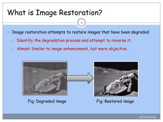

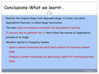
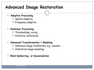


The document is a lecture presentation on image restoration in digital image processing, covering fundamental concepts such as degradation models, noise types, estimation methods, and restoration techniques. It differentiates between image enhancement and restoration, emphasizing the importance of known degradation models for restoring degraded images. Advanced restoration techniques and practical applications are also discussed, along with acknowledgements to various academic resources.