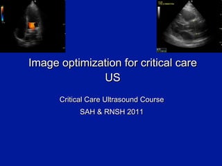
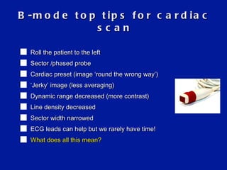
Image optimization for critical care US Critical Care Ultrasound Course SAH & RNSH 2011
Summary Revision: basic image optimization B- mode, M-mode, Doppler LUNG IVC HEART
Revision: basic image optimisation
Revision: basic image optimisation Patient position (supine? left lateral?) Lighting (dark) Enough gel Right probe Right orientation Right preset Right depth Overall gain Individual TGC/DGC sliders
Revision: basic image optimisation Frequency Focal Zones (how deep? how many?) Cheat buttons  -  Auto –optimize Harmonics Change your angle & pressure Zoom
Harmonics (THI) As a sound wave travels through tissue, the high pressure bit (compressing tissue) moves  faster  than the rarefactional component.  This  distorts  the wave! and generates higher frequency components ( harmonics ) deep in the tissues. eg 3MHz wave creates 6MHz, 12 MHz harmonics
Harmonics (THI) Q: So what? A: it turns out that aberrant/artefact signals are too  weak  to generate harmonic waves. THI takes advantage of this: i.e. it displays  only  the harmonic signals. THI images have: reduced noise and clutter improved spatial resolution (harmonic beams are narrower than the original)
Same Kidney, difficult patient No Harmonics With Harmonics
Top tip:  Harmonics (THI) = another great button Don ’t use it for the lung For other regions, give it a go If it makes the image worse, press again to turn it off Best for  mid-depth  images. harmonic generation does not take place near the skin, so THI no use there.  Also less useful in far field.
M mode
M mode = motion mode Press  ‘ M ’  button once & a line appears Use touch pad / track ball to move the line to area of interest Press  ‘ M ’  again to plot a graph of  what that line sees versus time Stationary stuff = straight line Moving things = curved/ dots
M-mode: what ’ s the point? CONS If angles wrong, measurements wrong! Easier to stuff up than B-mode IF IN DOUBT, USE B MODE PROS M-mode (motion mode) = movement along a  single  line of info against time Single line therefore much better sensitivity & resolution More accurate dimensions
M mode: poorly contractile LV
M mode: IVC changing with respiration
Doppler
Doppler effect Probe sends a sound wave of known frequency If it hits object moving towards probe, the returning sound wave is  higher  frequency If object moving away, the returning wave is  lower  frequency
Today:  we   leave Doppler alone Master the basics first Know your limitations
Sreening exam: scanning the lungs
LUNGS: probe & preset PROBE Not  the linear array (too much fine detail!) … False neg PTX (movement) … False pos PTX (pain) The  curved  probe is best  Image quality Anatomy The  phased  array probe fits b/w ribs & gets round the back PRESET One with plenty of greyscale/ dynamic range Abdo preset (abdo > FAST) NOT cardiac preset Turn  off  the fancy filters: THI, compounding/MB etc- they make the artefacts harder to see!
Depth & alignment DEPTH 5cm:  just for pleura eg sliding 10cm:  to confirm true B lines 15cm:  anatomical relations, diaphragm, effusions PROBE ALIGNMENT Surprisingly, stay sagittal (perpendicular to ribs) Only turn parallel if interrogating structures further eg solid areas
Screening exam: the IVC
Probe & preset PROBE C urved  probe is best  Image quality Anatomy Phased array probe if already on TTE PRESET Whatever preset you’re on is fine
Screening exam: single view heart Keep it simple Same probe & preset
Trans thoracic echocardiogram (TTE) We ’re not in Kansas any more
B-mode top tips for cardiac scan Roll the patient to the left Sector /phased probe Cardiac preset (image  ‘ round the wrong way ’ ) ‘ Jerky ’  image (less averaging) Dynamic range decreased (more contrast) Line density decreased Sector width narrowed ECG leads can help but we rarely have time! What does all this mean?
The bottom line The heart beats very quickly We need to capture this movement accurately So we maximise  ‘ temporal resolution ’ = increased frame rate And we turn off averaging = only  ‘ true ’  images are seen But we sacrifice something to achieve this: mainly  spatial  resolution i.e. the image has less anatomical detail = lower  ‘ line density ’ And less greyscale /dynamic range (ie it ’ s a more  ‘ black & white ’  picture) So we need to try certain  ‘ tricks ’  to improve our image  within these limits e.g: - decrease depth - zoom the image - decrease sector width
Why the jerky image? Image not as smooth No averaging = no  ‘ fudging ’ What you see on screen is really there
What ’ s Line Density? How many lines per frame A high line density is desirable for high resolution imaging of small parts (thyroid, breast testes…),  A lower line density is useful in  cardiac  applications as it allows significantly higher frame rates. Reference: LOGIQ 9 Basic User Manual, Direction 5140804 -100 Rev.3  5-24
Sector Width (Scan Area) Allows you to widen or narrow the sector angle to maximise the region of interest (ROI), and maximise frame rate. You can usually steer the narrowed sector as well, useful for looking in corners! Top tip: keep sector as  narrow  as possible
Summary Critical care echo is where it ’ s at TTE i s tricky! But screening exam is simple
References Roger Gent: Applied Physics & Technology of Diagnostic Ultrasound 1997 Sam Kaddoura: Echo Made Easy Cindy Lucas, senior sonographer Liverpool Hospital

Image Optimization for Critical Care Ultrasound

  • 1.
    Image optimization forcritical care US Critical Care Ultrasound Course SAH & RNSH 2011
  • 2.
    Summary Revision: basicimage optimization B- mode, M-mode, Doppler LUNG IVC HEART
  • 3.
  • 4.
    Revision: basic imageoptimisation Patient position (supine? left lateral?) Lighting (dark) Enough gel Right probe Right orientation Right preset Right depth Overall gain Individual TGC/DGC sliders
  • 5.
    Revision: basic imageoptimisation Frequency Focal Zones (how deep? how many?) Cheat buttons - Auto –optimize Harmonics Change your angle & pressure Zoom
  • 6.
    Harmonics (THI) Asa sound wave travels through tissue, the high pressure bit (compressing tissue) moves faster than the rarefactional component. This distorts the wave! and generates higher frequency components ( harmonics ) deep in the tissues. eg 3MHz wave creates 6MHz, 12 MHz harmonics
  • 7.
    Harmonics (THI) Q:So what? A: it turns out that aberrant/artefact signals are too weak to generate harmonic waves. THI takes advantage of this: i.e. it displays only the harmonic signals. THI images have: reduced noise and clutter improved spatial resolution (harmonic beams are narrower than the original)
  • 8.
    Same Kidney, difficultpatient No Harmonics With Harmonics
  • 9.
    Top tip: Harmonics (THI) = another great button Don ’t use it for the lung For other regions, give it a go If it makes the image worse, press again to turn it off Best for mid-depth images. harmonic generation does not take place near the skin, so THI no use there. Also less useful in far field.
  • 10.
  • 11.
    M mode =motion mode Press ‘ M ’ button once & a line appears Use touch pad / track ball to move the line to area of interest Press ‘ M ’ again to plot a graph of what that line sees versus time Stationary stuff = straight line Moving things = curved/ dots
  • 12.
    M-mode: what ’s the point? CONS If angles wrong, measurements wrong! Easier to stuff up than B-mode IF IN DOUBT, USE B MODE PROS M-mode (motion mode) = movement along a single line of info against time Single line therefore much better sensitivity & resolution More accurate dimensions
  • 13.
    M mode: poorlycontractile LV
  • 14.
    M mode: IVCchanging with respiration
  • 15.
  • 16.
    Doppler effect Probesends a sound wave of known frequency If it hits object moving towards probe, the returning sound wave is higher frequency If object moving away, the returning wave is lower frequency
  • 17.
    Today: we leave Doppler alone Master the basics first Know your limitations
  • 18.
  • 19.
    LUNGS: probe &preset PROBE Not the linear array (too much fine detail!) … False neg PTX (movement) … False pos PTX (pain) The curved probe is best Image quality Anatomy The phased array probe fits b/w ribs & gets round the back PRESET One with plenty of greyscale/ dynamic range Abdo preset (abdo > FAST) NOT cardiac preset Turn off the fancy filters: THI, compounding/MB etc- they make the artefacts harder to see!
  • 20.
    Depth & alignmentDEPTH 5cm: just for pleura eg sliding 10cm: to confirm true B lines 15cm: anatomical relations, diaphragm, effusions PROBE ALIGNMENT Surprisingly, stay sagittal (perpendicular to ribs) Only turn parallel if interrogating structures further eg solid areas
  • 21.
  • 22.
    Probe & presetPROBE C urved probe is best Image quality Anatomy Phased array probe if already on TTE PRESET Whatever preset you’re on is fine
  • 23.
    Screening exam: singleview heart Keep it simple Same probe & preset
  • 24.
    Trans thoracic echocardiogram(TTE) We ’re not in Kansas any more
  • 25.
    B-mode top tipsfor cardiac scan Roll the patient to the left Sector /phased probe Cardiac preset (image ‘ round the wrong way ’ ) ‘ Jerky ’ image (less averaging) Dynamic range decreased (more contrast) Line density decreased Sector width narrowed ECG leads can help but we rarely have time! What does all this mean?
  • 26.
    The bottom lineThe heart beats very quickly We need to capture this movement accurately So we maximise ‘ temporal resolution ’ = increased frame rate And we turn off averaging = only ‘ true ’ images are seen But we sacrifice something to achieve this: mainly spatial resolution i.e. the image has less anatomical detail = lower ‘ line density ’ And less greyscale /dynamic range (ie it ’ s a more ‘ black & white ’ picture) So we need to try certain ‘ tricks ’ to improve our image within these limits e.g: - decrease depth - zoom the image - decrease sector width
  • 27.
    Why the jerkyimage? Image not as smooth No averaging = no ‘ fudging ’ What you see on screen is really there
  • 28.
    What ’ sLine Density? How many lines per frame A high line density is desirable for high resolution imaging of small parts (thyroid, breast testes…), A lower line density is useful in cardiac applications as it allows significantly higher frame rates. Reference: LOGIQ 9 Basic User Manual, Direction 5140804 -100 Rev.3 5-24
  • 29.
    Sector Width (ScanArea) Allows you to widen or narrow the sector angle to maximise the region of interest (ROI), and maximise frame rate. You can usually steer the narrowed sector as well, useful for looking in corners! Top tip: keep sector as narrow as possible
  • 30.
    Summary Critical careecho is where it ’ s at TTE i s tricky! But screening exam is simple
  • 31.
    References Roger Gent:Applied Physics & Technology of Diagnostic Ultrasound 1997 Sam Kaddoura: Echo Made Easy Cindy Lucas, senior sonographer Liverpool Hospital