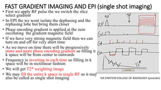
1. MRI GRADIENT ECHO
PULSE SEQUENCE,TYPES
AND APPLICATIONS
Presenter :Sujan Karki
B.Sc. MIT 3rd year
National Academy of Medical Sciences(NAMS)
Bir Hospital
2. Topics Included
1. Introduction
2. Spatial encoding (briefly)
3. Coherent gradient echo
4. Incoherent or Spoiled gradient echo
5. Steady state free precession
6. Balanced steady state
7. Fast gradient echo (EPI)
8. Reference
3. INTRODUCTION
• Gradients are the coils of wire that when
current is passed through them ,they alter
the magnetic field strength in a controlled
and predictable way
• They either add or subtract from the existing
field in a linear fashion
• Isocentre is the point where field strength
remain unchanged even when the gradient
is switched on
• Today, most MRI scanner manufacturers
employ distributed windings in a
“fingerprint” pattern.
4. Gradient Axes
• Here are three gradient coils situated within the bore
of the magnet
• They are named according to the axis along which they
act when they are switched on.
• Shows these directions in a typical superconducting
magnet,some manufacturers may use a different
system.
Fig:Gradient labeling.
5. Why is it called RECALLED ECHO??
• In GRE we will intentionally dephase the FID and
rephase (or recall) it at a more convenient time,
namely, at TE.
• In the figure we have bilobed gradient in x
direction which first dephases the spins and then
rephases them in the readable form.
• The area under the negative lobe is equal to half
the area under the positive lobe(??). The
refocusing occurs at the midpoint of the positive
lobe.
• In GRE we first diphase the FID and then Rephase
it in time TE so it is called Gradient Recalled
6. WHAT IS THE REASON FOR NOT USING A 180
degree RF pulse IN GRE??
•If we use 180 degree RF pulse then
the longitudinal magnetization will
be flipped to south and we need
longer TR ,which is not desirable in
GRE sequence.
7. HISTORY OF GRE NOMENCLEATURE
• Bloch et al and Purcell et al demonstrated
the phenomenon of nuclear induction in the
year 1946 but in the year 1950 Hahn
recorded the transient MR signal after the RF
which is now called as FID.
• In the same year Hahn reported the discovery
of a remarkable new type of MR signal the
SE which could be generated by application
of 2 successive RF pulse
• In collaboration with other scientists Hahn
discovered that train of three or more RF
pulse could produce third type of MR signal
STIMULATED ECHO.
Allen D etal 1993
8. Why gradient echo sequences ????
1. For fast imaging applications
because we use short TR and TE in GRE and it is applicable in real time
imaging ,breath hold techniques and 3D imaging etc.
2.RF energy deposition is less in comparison to SPIN echo sequences(SAR)
because it uses the low flip angle and is applicable when the heating risk are
concern
3.Image contrast is flexible
because we can adjust TR,TE and Flip Angle to characterize a tissue.
4.To obtain bright blood signal
during the cardiovascular and angiographic examinations the inflowing blood
in the vessel is in motion and it might not see the various RF pulses.
9. Some Drawbacks of gradient echo
1)T2* weighting rather then T2 weighting
because GRE do not use 180 degree refocusing
pulse
2)It is more sensitive to off-resonance (field
inhomogeneity , susceptibility) because it do not have
180 refocusing pulse.
3) Peripheral nerve stimulation (tingling sensation )
and acostic noise
11. Slice Selection Gradient
1. When the gradient is turned on it alters the
magnetic field strength in the linear fashion at the
selected slice and changes the precessional
frequency of that particular slice to resonate with
the applied RF.
2. In the given figure if we want excite the slice A
then we should apply the RF of 63.76MHz and if
slice b is to be excited then we should apply the RF
of 63.86MHz
3. Slice gap is the space between two slices
4. Too small slice gap leads to the cross excitstion
artefact
5. It is switched on during the delivery of RF pulse for
about 3.2ms
(Where W is Lamour frequency ,Bo is main magnetic field strength ,Gz is gradient on z axis and z is distance of
slice from isocentre) Magnetic field gradients
figure
isocenter
Magnetic field gradients
12. Slice thickness
Slice thickness is determined by range of
frequency called bandwidth more
specifically transient bandwidth because
RF is transmitted at the instant.
thin slice = steep gradient and narrow
bandwidth = spatial resolution also
increases
thick slice = shallow gradient and broad
bandwidth = spatial resolution will
decrease.
13. Phase Encoding Gradient
• Once the gradient is turned off the spins will
stop precessing, but they will retain the phase
they had due to the phase-encoding gradient
• It is turned on for about 4 ms and amplitude and
polarity is altered for each phase encoding
gradient.
• We use phase encoding gradient after the slice
excitation and before the frequency or readout
gradient
• We use phase encoding in 1 direction for 2D
imaging and we use it in 2 direction for 3D
imaging .
• Phase shift is the change in the position after
the gradient is switched off but the processional
frequency will be same as earlier.
14. Frequency Encoding Gradient
• Frequencies within the signal are read by the system
during its application so it is also called readout
gradient or measurement gradient , it is turned on
for about 8 ms.
• Frequency change or frequency shift caused by the
gradient is used to locate the signal.
• The slope of frequency encoding gradient determines
the size of the FOV and therefore the image
resolution.
A large current produces a higher amplitude(steep
gradient ) and this creates small FOV
A small current produces a lower amplitude(shallow
gradient ) and creates larger FOV
15. Basic Gradient Echo Sequence
FID decay due to T2 decay
and spin dephasing
Gradient accelerates
spin dephasing
gradient can also rephase
the spins and produce an
echo
16. Hydrogen protons before the application of RF pulse
Protons after the application of RF pulse move to
the transverse plane
Here after the gradients causes the change in magnetic field and the proton starts dephasing
The rephasing gradient rephases the protons and at
echo is collected
Now again dephasing of protons by the second half of
bilobed gradients
17. Steady state
• Condition where TR is shorter than both T1and
T2 relaxation time of tissues
• Transverse magnetization has not completely
decayed before the application of next TR
• So residual transverse magnetization
accumulation over the successive TR affects the
contrast.
• The only process that has time to occur is T2*
• To maintain the steady state short TR(22-50)and
medium flip angle(30-45) is required.
• Most of gradient echo sequence utilizes steady
for fastest image acquisition .
18. Coherent gradient echo( FFE,GRASS,FISP)
• It uses the steady state by using very short TR and
medium flip angle so there is a residual transverse
magnetization
• We use rewinder gradient or rephasing in the
opposite polarity of phase encoding direction with
same amplitude and it results in the rephasing of
the residual transverse magnetization and keep it
in phase therefore it is preserved when the next
excitation is applied
• As the residual transverse coherence is retained
the tissues with long T2 times are hyperintense
like blood ,csf and fluid.
• Conventionally they produces the T2* weighted
images with long TE but by manipulating
parameter we can obtain T1 and PD weighting
images also.
19. • Typical parameters(For T2* weighting)
TR: 20-50ms TE:10-15ms flip angle:30-45
degree
• FOR T1 weighting
TR: 400ms TE:5ms flip angle:90 degree
• For PD weighting
TR: 400ms TE:5ms flip angle:20 degree
Applications
We use coherent gradient echo to produce T2*
weighting in a very short scan time and as water is
hyperintense they are used in angiographic,
myelography and arthographic examinations. They
also are used to determine whether an area
contains fluid.
Coherent axial slice of abdomen
coherent Sagittal slice of
knee
20. Incoherent gradient echo(SPGR,FLASH,T1-FFE
• It uses the steady state by using very
short TR and medium flip angle
• Uses a gradient rephasing instead of
180 degree RF pulse
• Eliminates the residual transverse
magnetization so that tissue with
long T2 times are not allowed to
dominate image contrast but T1/PD
contrast can be obtained
• TE should be as short as possible to
minimize the T2* effects
Incoherent
sagittal image
of ankle
IncoherentCoronal
image
Post contrast
21. Why spoiling is important ????
1. It eliminates the transverse magnetization
after each TR which prevents the errors
related to transverse magnetization.
2. It shortens the TR, if spoilers are not used
then we have to wait for 5xT2*
3. With the help of spoilers we can enhance
T1 contrast
22. RF SPOILING
It is considered as the powerful technique of removing
the signal contribution from the residual transverse
magnetization
Here in each TR magnetization is tipped in different axis.
In quadratic phase cycling, the phase for the nth RF
pulse is given by phi=n(n+1)phi and constant increment,
phi.
From spoiling we get T1 contrast because of proper
phase increment
If we suppress the residual transverse magnetization then
the signal will be independent of T2,resulting in T1
signal .
Karla L Miller etal 2011
23. Gradient Spoiling
• It is one of the easiest method of spoiling where the
gradient pulse is used to create a range of phase
angles across the voxel.
• The main purpose here is avoid rephasing in each TR.
• We should apply the gradient of different amplitude in
each TR to avoid the rephasing
• However achieving a broad range of variable areas
require either strong gradient or long TR ,making this
impractical in most circumstances
Karla L Miller etal 2011
24. Long TR Spoiling
• For long TR spoiling we must
have to wait for about 5 times the
T2* decay, ie we must let the
complete dephasing
• We must wait for about 99% of
the recovery of longitudinal
magnetization .
• It will increase the scan time
Qa in mri
25. • Typical parameters(For T1 weighting )
TR: 20-50ms TE:5-10ms flip angle:30-45 degree
• In addition:
Average scan time – several seconds for single slice, minutes for volumes.
Applications
These sequences are used for 2D and volume acquisitions, and, as the TR is
short, 2D acquisitions are used to obtain T1-weighted breath-hold images.
Incoherent or spoiled gradient-echo sequences also demonstrate good T1
anatomy and pathology after gadolinium contrast enhancement
26. T2 VS T2*
• T2 is defined as a time constant for the
decay of transverse magnetization arising
from natural interactions at the atomic or
molecular levels
• transverse magnetization decays much
faster than would be predicted by natural
atomic and molecular mechanisms; this
rate is denoted T2* ("T2-star").
• T2* is always less than or equal to T2.
• T2* results principally from
inhomogeneities in the main magnetic
field.
• T2* weighting are generally used for the
detection of small hemorrhages and
calcifications
27. To produce same contrast there are these
differences in parameters in spin echo and
gradient echo
Via ucla radiography
28. Ernest Angle
• It is the flip angle which gives the
maximum MRI signal at the given
TR and T1
30. Balanced Steady-State Free Precession (bSSFP,True
FISP,FIESTA)
• "Balanced" means that the net gradient-
induced dephasing over a TR interval is
zero.
• The signal intensity is seen to be the
ratio T2/T1.
• To obtain balanced steady state we
sample both FID and ECHO
• In balanced gradient echo gradients are
applied in slice and frequency axis .
• Higher flip angle and shorter TR is used
than in coherent echo so higher SNR and
shorter scan time
• highlight fluids such as CSF and blood,
making them ideal for cardiovascular
MRI, MR cisternography/myelography,
MR urography, and MR enterography.
31. banding artefact
• The refocusing mechanism fails if
intravoxel dephasing exceeds ±180º
manifest by band-like artifacts.
• They are also more problematic in 3D
acquisitions where TR values may
exceed 10-15 msec.
• banding artifacts appear as a result of
off-resonance effects, improved
shimming can also mitigate the
appearance of these artifacts.
• To ameliorate the banding artifacts,
the TR should be minmized,
32. Typical parameters(T2/T1 contrast)
• Flip angle variable (larger flip angles increase signal)
• Short TR less than 10 ms (reduces scan time and flow artifact)
• Long TE 5–10 ms.
Advantages Disadvantages
Shorter scan time Reduced SNR in 2D acquisitions
Reduced artifacts from flow Loud gradient noise
Good SNR and anatomical detail in 3D
imaging
Susceptible to artefacts
Image demonstrate good contrast Requires high performance gradients
Advantages and disadvantages of balanced
gradient echo
Axial balanced gradient-echo
image of the lumbar spine.
33. Steady State Free Precession (SSFP,T2FFE,PSIF)
• It gives T2 weighted image
• RF contain various amplitude and some are
capable of rephasing the FID.
• Each RF pulse therefore not only produces its
own FID, but also rephases the FID produced
from the previous excitation.
• The echo from the first excitation pulse
occurs at the same time as the third excitation
pulse. RF cannot be transmitted and received
at the same time. To prevent this, a rewinder
gradient is used to speed up the rephasing
process after the RF rephasing has begun.
Via mri at glance
34. Ssfp cont.
• In SSFP here are two TE:
• Actual TE (time between echo and next
RF pulse)
• Effective TE(time from the echo to the
excitation pulse that created its FID)
rephasing is done by RF so that to
reduce the off-resonance effects i.e more
T2 than T2*.
Via mri at glance
Acronyms of SSFP
35. T2 weighting image produced by SSFP
• SPSS is generally used in acquiring T2
weighting contrast which is useful in
brain and joints for the 2D and 3D
acquisitions.
• They are replaced by TSE as TSE
produce the T2 weighting image in
shorter scan time.
Image via MRI in practice
36. Dual Echo Steady State(DESS)
• DESS generates the FID-like and Echo-like signals from
the steady-state free precession individually.
• Phase-encoding and slice-select gradients are balanced
to maintain the transverse steady state.
• The contrast of DESS is unique as it combines features
from both the FID-signal of FISP with the Echo-signal
of PSIF.
• Fluid is extremely bright and Bone is relatively dark due
to T2* dephasing from trabeculae.
37. MERGE
• MERGE ("Multiple Echo Recombined Gradient
Echo") is a spoiled T2*-weighted sequence for
spinal and musculoskeletal imaging
• By reversing the frequency-encoding gradient
rapidly, several individual gradient echoes can be
generated at different TEs. The number of echoes
is limited by T2*-decay, but typically between 3-5
echoes are recorded.
38. GRASE(Gradient and Spin Echo)
• It is a hybrid technique that generates and records a series of
alternately acquired gradient echoes and spin echoes from a train of
RF-pulses. In its original implementation, a 90°-RF pulse was
followed by series of eight 180°-refocusing pulses, generating eight
spin echoes. Centered about (and overlapping) each spin echo, three
gradient echoes were produced by rapidly switching the readout
gradient polarity. The final data set consisted of 24 separate MR
signals having properties intermediate between spin-echo and gradient
echo contrast.
• The advantage of GRASE is that the gradient echo component would
provide increased sensitivity for detecting calcifications and
hemorrhages (often difficult to see on SE) while not having too much
susceptibility artifact at normal anatomic interfaces. Additionally the
energy deposition (SAR) is lower than a comparable fast spin-echo
sequence because there are fewer RF-pulses.
T2- vs T2*-weighting can be obtained
39. FIESTA_C/CISS
• modification of the basic FIESTA/TrueFISP sequence
• composed of a pair of TrueFISP acquisitions run back-to-
back preceded by an automatic shimming procedure.
• The first uses phase alternation of the RF-pulses
(+α, −α, +α, −α, ...) while the second does not (+α, +α, +α,
etc).
• When the paired data sets are combined in maximum
intensity projection, the phase errors cancel, resulting in an
image largely free of dispersion banding
• combination of paired signals is performed automatically
after data collection
• FIESTA-C/CISS is currently the sequence of choice for
CSF-cisternography for visualizing cranial nerves at the
skull base.
40. FAST GRADIENT IMAGING AND EPI (single shot imaging)
• First we apply RF pulse the we switch the slice
select gradient
• In EPI the we wont isolate the dephasing and the
rephasing lobe but bring them closer
• Phase encoding gradient is applied at the zero
oscillating the gradient magnetic field
• If we have very strong magnetic field then we can
turn on and off for very short time
• As we move on time there will be progressively
more and more phase encoding gradient so filling in
k space will be from center to outwards
• Frequency is inverting in each time so filling in k
space will be in rectilinear fashion
• We will get T2* weighting image
• We may fill the entire k space in single RF so it may
also be called as single shot imaging VIA EINSTEIN COLLEGE OF RADIOLOGY (youtube)
41.
42. Bibliography
• MAGNETIC RESONANCE IMAGING Physical and Biological PrinciplesStewart Carlyle Bushong, ScD, FAAPM, FACR Professor
of Radiologic Science Baylor College of Medicine Houston, Texas Geoffrey Clarke, PhD Professor and Chief of Graduate
Education Department of Radiology The University of Texas Health Science Center at San Antonio San Antonio, Texas
• MRI Basic Principles and Applications Brian M. Dale, PhD MBA Mark A. Brown, PhD Richard C. Semelka, MD FIFTH EDITION
• MRI at a Glance Catherine Westbrook
• Steady-state MRI: methods for neuroimagingKarla L Miller†1, Rob HN Tijssen1 , Nikola Stikov2 & Thomas W Okell12011
• CT AND MRI OF THE WHOLE BODY Sixth Edition John R. Haaga, MD, FACR, FSIR, FSCBT, FSRS
• MRI From Picture to Proton
• MRI in Practice 4th and 5th Edition Catherine Westbrook MSc, FHEA, PgC(HE), DCRR, CTC
• Rapid Gradient-Echo Imaging Brian A. Hargreaves, PhD*2012
• FLASH Imaging. Rapid NMR Imaging Using Low Flip-Angle Pulses A. HAASE, J. FRAHM, D. MATTHAEI, W. H,&NICKE, AND K.-
D. MERBOLDT
• www.ucla radiography
• Questions and answers in mri
• Steady-State MR Imaging Sequences: Physics, Classification, and Clinical Applications1
• Gradient echo MR imaging techniques and acronyms
• Einstein institute of medicine
Editor's Notes
Fast field echo
Gradient recalled acquisition in steady state
Fast imaging with steady state
Spoiled grass
Fast low angle shot
Requires phase enconding rewinder
Dephases spins within voxels,
Variable gradient on each TR