Downloaded 1,651 times

![Fourier Slice Theorem Ky Kx F(Kx,Ky) F[P( t)] P( t) f(x,y) t y x X-rays](https://image.slidesharecdn.com/ct-124292972908-phpapp02/85/CT-Scan-Image-reconstruction-18-320.jpg)
![From Projections to Image y x Ky Kx F -1 [F(Kx,ky)] f(x,y) P( t) F(Kx,Ky)](https://image.slidesharecdn.com/ct-124292972908-phpapp02/85/CT-Scan-Image-reconstruction-20-320.jpg)


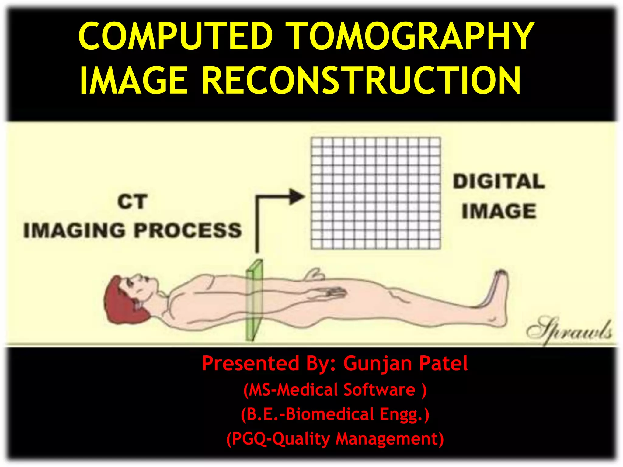
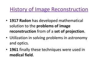
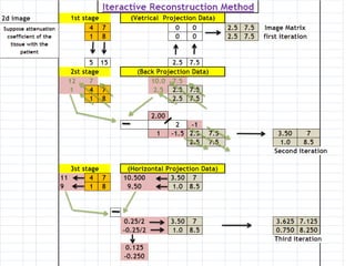
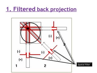
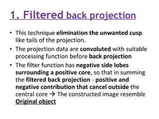
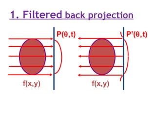
1. Computed tomography (CT) image reconstruction involves estimating digital images from measured x-ray projection data. Early methods included back projection, which was simple but produced blurred images. 2. Modern commercial CT scanners use analytical methods like filtered back projection or Fourier filtering to reduce blurring. These methods apply spatial or frequency domain filters to projection data before back projecting to reconstruct the image. 3. Iterative reconstruction methods were also developed and provide better image quality than analytical methods but are too computationally intensive for clinical use. Current research aims to make iterative methods fast enough for real-time medical imaging.


![Getting Started with Apache Spark: Big Data Made Simple [Free Meetup]](https://cdn.slidesharecdn.com/ss_thumbnails/apachesparkgettingstarted-260203175547-8361bcc3-thumbnail.jpg?width=640&height=640&fit=bounds)


