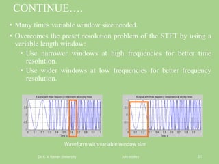
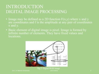
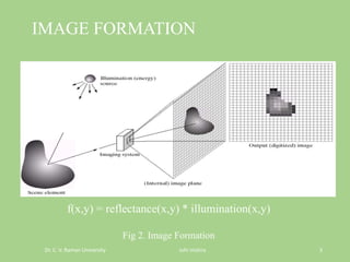
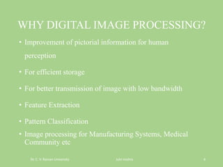
The presentation by Juhi Mishra discusses image enhancement techniques and their importance in digital image processing, highlighting the significance of improving visual information for human perception and efficient storage. It covers various types of noise affecting images, filtering techniques for noise reduction, and methods like wavelet analysis and thresholding for better image segmentation. The presentation emphasizes the need for effective filtering methods to enhance image quality in various applications.

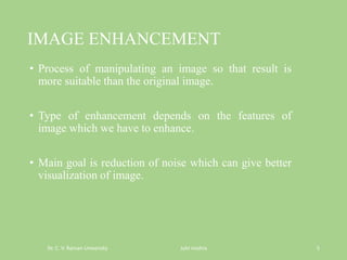
![REGULAR MEDIAN FILTER
Dr. C. V. Raman University Juhi mishra 10
225 225 225 226 226 226 226 226
225 225 226 226 226 226 226 226
225 226 226 226 226 226 226 226
226 226 225 225 226 226 226 226
225 225 225 225 226 226 226 226
225 225 225 226 226 226 226 226
225 225 225 226 226 226 226 226
226 226 226 226 226 226 226 226
225 225 225 226 226 226 226 226
225 225 255 226 226 226 225 226
226 226 225 226 226 226 226 255
255 226 225 0 226 226 226 226
225 255 225 225 226 226 226 255
255 225 224 226 226 0 225 226
226 225 225 226 255 226 226 228
226 226 225 226 226 226 226 226
Sorted: [0, 225, 225, 225, 225, 226, 226, 226, 226]
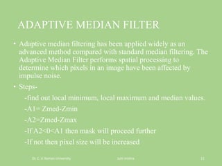
The median filter is normally used to reduce noise in an
image, somewhat like the mean filter. However, it often does
a better job than the mean filter of preserving useful detail in
the image.](https://image.slidesharecdn.com/imageenhancement-160930161731/85/Image-enhancement-10-320.jpg)