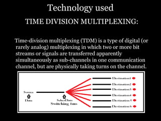
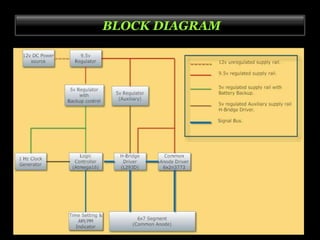
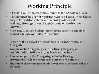
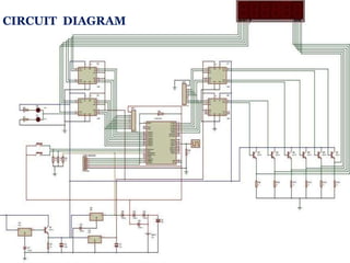
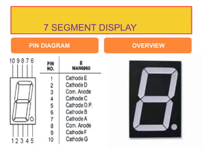
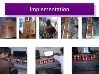
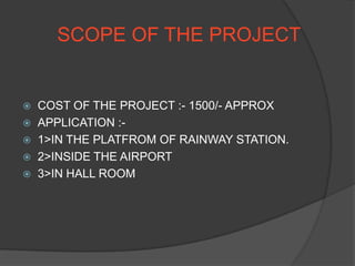
ELITE POLYTECHNIC INSTITUTE
MOGRA,HOOGHLY
Interrupt Driven Multiplexed 7 Segment
Digital Clock
WELCOME
OUR GROUP MEMBERS
SANTANU CHATTERJEE (05)
SUDIPTA KR .MUKHREJEE (29)
SAURABH BHAR (30)
BAPI THAKUR (31)
SOUMIK PRAMANIK (34)
SUMIT SAHA (35)
AMIT KR .KIRAN (36)
MD. AZIZ (62)
FALGUNI MUKHOPADHYAY (64)
 As student of electronics & telecommunication engineering of
diploma (6th semester) from WBSCTE, we should be glad as
we are permitted to do a project in the “Interrupt Driven
Multiplexed 7 Segment DIGITAL CLOCK”.
 At first, we are thankful to the respected Principal Dr. A.K DEY
Head Of Department (Electronics & telecommunication
Engineering), Mr. RANJAN DEVNATH , Mr. SOUTAK BISWAS
& TRISHA BISWAS and all of the E.T.C.E faculty members . It
is not easy to learn throughout knowledge of full system of
Digital Clock. But they always try to give the layout of the
whole process of production step by step & also try to answer
our curiosity conceptually. We are thankful to all.
CONTENTS
 INTRODUCTION
 TECHNOLOGY USED
 HARDWARE DESIGN
 BLOCK DIAGRAM
 WORKING PRINCIPLE
 CIRCUIT DIAGRAM
 COMPONENT DESCRIPTION
 SOFTWARE DESIGN
 SCOPE OF PROJECT
 ADVANTAGES
 FUTURE IMPROVEMENTS
 REFERENCE
INTRODUCTION
• A digital clock is a type of clock that displays the
time digitally, i.e. in numerals or other symbols, as
opposed to an analog clock, where the time is
indicated by the positions of rotating hands. Digital
clocks are often associated with electronic
drives, but the "digital" description refers only to
the display, not to the drive mechanism. (Both
analog and digital clocks can be driven either
mechanically or electronically, but "clockwork"
mechanisms with digital displays are rare.) The
biggest digital clock is the Lichtzeitpegel ("Light
Time Level") on the television tower Rheinturm
Düsseldorf, Germany.
OBJECTIVE OF THE PROJECT
 We do not used IC to drive 7segment display, to
simplify the circuitry than other IC based digital
clock.
 Using microcontroller the power consumption is less
than other same size digital clock.
Technology used
TIME DIVISION MULTIPLEXING:
Time-division multiplexing (TDM) is a type of digital (or
rarely analog) multiplexing in which two or more bit
streams or signals are transferred apparently
simultaneously as sub-channels in one communication
channel, but are physically taking turns on the channel.
BLOCK DIAGRAM
Working Principle
• A t first 12 volt dc power source applied to the 9.5 volt regulator.
• The output of the 9.5 volt regulator given to 4 blocks. These blocks
are 5 volt regulator with backup control, 5 volt regulator
auxiliary, H-Bridge driver (L293D)& common anode driver
(2n3773).
• 5 volt regulator with backup control giving supply to 1Hz clock
generator & logic controller (Atmega16).
• Output of the 1hz clock generator goes to the logic controller
Atmega16.
• 1 output of the Atmega16 goes to the time setting am/pm
indicator, which indicate am/pm & setting the time.
• Another output of the Atmega16 goes to the H-bridge
driver(L293D),which operate each segment of 7 segment.
• The output of the common anode driver goes to the anode of all 7
segment.
HCIRCUIT DIAGRAM
IC ATMEGA16
The ATMega16 Seven Segment Digital Clock
• In this ATMega16 AVR project we will be designing and
implementing a digital clock with the aid of a Atmel AVR
ATMega16 microcontroller and Seven Segment Displays. As
such before going through this digital clock AVR project it is
recommended to complete the tutorial on Interfacing a Seven
Segment Display with the AVR Microcontroller.
Note: Although this AVR project was designed around the
ATMega16 the project could have utilized another
microcontroller such as an ATMega32, ATMega8515, etc.
ATMega16 Digital Clock Operation
Our digital clock operates as follows. When the circuit is
powered up the clock starts at "00:00:00" for "HH:MM:SS".
There are two push-button switches used to set the time.
Switch SW1 is for setting the minutes, when this button is
pressed the minutes in increase until it reaches 59 then reset and
start counting from 0. Switch SW2 is for setting thehours.
ATmega16(L)
Features
• High-performance, Low-power Atmel® AVR® 8-bit Microcontroller
• Advanced RISC Architecture
– 131 Powerful Instructions – Most Single-clock Cycle Execution
– 32 x 8 General Purpose Working Registers
– Fully Static Operation
– Up to 16 MIPS Throughput at 16 MHz
– On-chip 2-cycle Multiplier
• High Endurance Non-volatile Memory segments
– 16 Kbytes of In-System Self-programmable Flash program memory
– 512 Bytes EEPROM
– 1 Kbyte Internal SRAM
– Write/Erase Cycles: 10,000 Flash/100,000 EEPROM
– Data retention: 20 years at 85°C/100 years at 25°C(1)
– Optional Boot Code Section with Independent Lock Bits
In-System Programming by On-chip Boot Program
True Read-While-Write Operation
– Programming Lock for Software Security
• JTAG (IEEE std. 1149.1 Compliant) Interface
– Boundary-scan Capabilities According to the JTAG Standard
– Extensive On-chip Debug Support
– Programming of Flash, EEPROM, Fuses, and Lock Bits through the JTAG Interface
• Peripheral Features
– Two 8-bit Timer/Counters with Separate Prescalers and Compare Modes
– One 16-bit Timer/Counter with Separate Prescaler, Compare Mode, and Capture
Mode
– Real Time Counter with Separate Oscillator
– Four PWM Channels
– 8-channel, 10-bit ADC
8 Single-ended Channels
7 Differential Channels in TQFP Package Only
2 Differential Channels with Programmable Gain at 1x, 10x, or 200x
– Byte-oriented Two-wire Serial Interface
– Programmable Serial USART
REGULATOR
7805
Description:
The KA78XX/KA78XXA series of three-terminal
positive regulator
are available in the TO-220/D-PAK package and
with several fixed output
voltages, making them useful in a wide range of
applications. If adequate heat sinking is
provided, they can
deliver over 1A output current. Although designed
primarily as fixed voltage
regulators, these devices can be used with external
components to obtain adjustable
voltages and currents.
Features:
· Output Current up to 1A
· Output Voltages of 5V
· Thermal Overload Protection
· Short Circuit Protection
Driver IC
L 293D PIN DIAGRAM
DataSheet:
• L293D
L293D is a dual H-bridge motor driver integrated circuit (IC). Motor drivers act as current
amplifiers since they take a low-current control signal and provide a higher-current signal.
This higher current signal is used to drive the motors.
•
L293D contains two inbuilt H-bridge driver circuits. In its common mode of operation, two
DC motors can be driven simultaneously, both in forward and reverse direction. The motor
operations of two motors can be controlled by input logic at pins 2 & 7 and 10 & 15. Input
logic 00 or 11 will stop the corresponding motor. Logic 01 and 10 will rotate it in clockwise
and anticlockwise directions, respectively.
•
Enable pins 1 and 9 (corresponding to the two motors) must be high for motors to start
operating. When an enable input is high, the associated driver gets enabled. As a result, the
outputs become active and work in phase with their inputs. Similarly, when the enable
input is low, that driver is disabled, and their outputs are off and in the high-impedance
state.
•
COOLING FAN
OPTOCUPLAR
• An optocoupler, also called opto-
isolator, is an electronic component
that transfers an electrical signal or
voltage from one part of a circuit to
another, or from one circuit to
another, while electrically isolating
the two circuits from each other. It
consists of an infrared emitting LED
chip that is optically in-line with a
light-sensitive silicon
semiconductor chip, all enclosed in
the same package. The silicon chip
could be in the form of a photo
diode, photo transistor, photo
Darlington, or photo SCR.
7 SEGMENT DISPLAY
PIN DIAGRAM OVERVIEW
Software Design
• Flow chart & description
Implementation
SCOPE OF THE PROJECT
 COST OF THE PROJECT :- 1500/- APPROX
 APPLICATION :-
 1>IN THE PLATFROM OF RAINWAY STATION.
 2>INSIDE THE AIRPORT
 3>IN HALL ROOM
ADVANTAGE OF OUR
PROJECT
• 1> LOW POWER CONSUMPTION THAN OTHER
DIGITAL CLOCK.
• 2> ITS COST IS LOW THEN OTHER SAME SIZE
DIGITAL CLOCK.
• 3> MAINTENANCE-FREE
• 4> IN THE DIGITAL CLOCK NO EXTERNAL
CRYSTAL IS USED.
DISADVANTAGE
• Heavy weight
• Date and alarm are not present in our
digital clock.
FUTURE IMPROVEMENT
 Scope to introduce the calender
 Introduce alarm
 Use as a controller to drive other energy saving devices
REFERENCE
 BOOK S : “ Basic Communication”, by FRENZEL
“ Electronics Devices and Circuits” , by
SANJIV GUPTA .
 WEBSITE : < http:// www.encyclopedia.com>
<http://www.engineersgarage.com>
THANKS TO ALL OF YOU

INTERRUPT DRIVEN MULTIPLEXED 7 SEGMENT DIGITAL CLOCK

  • 1.
    ELITE POLYTECHNIC INSTITUTE MOGRA,HOOGHLY InterruptDriven Multiplexed 7 Segment Digital Clock
  • 2.
    WELCOME OUR GROUP MEMBERS SANTANUCHATTERJEE (05) SUDIPTA KR .MUKHREJEE (29) SAURABH BHAR (30) BAPI THAKUR (31) SOUMIK PRAMANIK (34) SUMIT SAHA (35) AMIT KR .KIRAN (36) MD. AZIZ (62) FALGUNI MUKHOPADHYAY (64)
  • 3.
     As studentof electronics & telecommunication engineering of diploma (6th semester) from WBSCTE, we should be glad as we are permitted to do a project in the “Interrupt Driven Multiplexed 7 Segment DIGITAL CLOCK”.  At first, we are thankful to the respected Principal Dr. A.K DEY Head Of Department (Electronics & telecommunication Engineering), Mr. RANJAN DEVNATH , Mr. SOUTAK BISWAS & TRISHA BISWAS and all of the E.T.C.E faculty members . It is not easy to learn throughout knowledge of full system of Digital Clock. But they always try to give the layout of the whole process of production step by step & also try to answer our curiosity conceptually. We are thankful to all.
  • 4.
    CONTENTS  INTRODUCTION  TECHNOLOGYUSED  HARDWARE DESIGN  BLOCK DIAGRAM  WORKING PRINCIPLE  CIRCUIT DIAGRAM  COMPONENT DESCRIPTION  SOFTWARE DESIGN  SCOPE OF PROJECT  ADVANTAGES  FUTURE IMPROVEMENTS  REFERENCE
  • 5.
    INTRODUCTION • A digitalclock is a type of clock that displays the time digitally, i.e. in numerals or other symbols, as opposed to an analog clock, where the time is indicated by the positions of rotating hands. Digital clocks are often associated with electronic drives, but the "digital" description refers only to the display, not to the drive mechanism. (Both analog and digital clocks can be driven either mechanically or electronically, but "clockwork" mechanisms with digital displays are rare.) The biggest digital clock is the Lichtzeitpegel ("Light Time Level") on the television tower Rheinturm Düsseldorf, Germany.
  • 6.
    OBJECTIVE OF THEPROJECT  We do not used IC to drive 7segment display, to simplify the circuitry than other IC based digital clock.  Using microcontroller the power consumption is less than other same size digital clock.
  • 7.
    Technology used TIME DIVISIONMULTIPLEXING: Time-division multiplexing (TDM) is a type of digital (or rarely analog) multiplexing in which two or more bit streams or signals are transferred apparently simultaneously as sub-channels in one communication channel, but are physically taking turns on the channel.
  • 9.
  • 10.
    Working Principle • At first 12 volt dc power source applied to the 9.5 volt regulator. • The output of the 9.5 volt regulator given to 4 blocks. These blocks are 5 volt regulator with backup control, 5 volt regulator auxiliary, H-Bridge driver (L293D)& common anode driver (2n3773). • 5 volt regulator with backup control giving supply to 1Hz clock generator & logic controller (Atmega16). • Output of the 1hz clock generator goes to the logic controller Atmega16. • 1 output of the Atmega16 goes to the time setting am/pm indicator, which indicate am/pm & setting the time. • Another output of the Atmega16 goes to the H-bridge driver(L293D),which operate each segment of 7 segment. • The output of the common anode driver goes to the anode of all 7 segment.
  • 11.
  • 12.
  • 13.
    The ATMega16 SevenSegment Digital Clock • In this ATMega16 AVR project we will be designing and implementing a digital clock with the aid of a Atmel AVR ATMega16 microcontroller and Seven Segment Displays. As such before going through this digital clock AVR project it is recommended to complete the tutorial on Interfacing a Seven Segment Display with the AVR Microcontroller. Note: Although this AVR project was designed around the ATMega16 the project could have utilized another microcontroller such as an ATMega32, ATMega8515, etc. ATMega16 Digital Clock Operation Our digital clock operates as follows. When the circuit is powered up the clock starts at "00:00:00" for "HH:MM:SS". There are two push-button switches used to set the time. Switch SW1 is for setting the minutes, when this button is pressed the minutes in increase until it reaches 59 then reset and start counting from 0. Switch SW2 is for setting thehours.
  • 14.
    ATmega16(L) Features • High-performance, Low-powerAtmel® AVR® 8-bit Microcontroller • Advanced RISC Architecture – 131 Powerful Instructions – Most Single-clock Cycle Execution – 32 x 8 General Purpose Working Registers – Fully Static Operation – Up to 16 MIPS Throughput at 16 MHz – On-chip 2-cycle Multiplier • High Endurance Non-volatile Memory segments – 16 Kbytes of In-System Self-programmable Flash program memory – 512 Bytes EEPROM – 1 Kbyte Internal SRAM – Write/Erase Cycles: 10,000 Flash/100,000 EEPROM – Data retention: 20 years at 85°C/100 years at 25°C(1) – Optional Boot Code Section with Independent Lock Bits In-System Programming by On-chip Boot Program True Read-While-Write Operation – Programming Lock for Software Security • JTAG (IEEE std. 1149.1 Compliant) Interface – Boundary-scan Capabilities According to the JTAG Standard – Extensive On-chip Debug Support – Programming of Flash, EEPROM, Fuses, and Lock Bits through the JTAG Interface • Peripheral Features – Two 8-bit Timer/Counters with Separate Prescalers and Compare Modes – One 16-bit Timer/Counter with Separate Prescaler, Compare Mode, and Capture Mode – Real Time Counter with Separate Oscillator – Four PWM Channels – 8-channel, 10-bit ADC 8 Single-ended Channels 7 Differential Channels in TQFP Package Only 2 Differential Channels with Programmable Gain at 1x, 10x, or 200x – Byte-oriented Two-wire Serial Interface – Programmable Serial USART
  • 15.
    REGULATOR 7805 Description: The KA78XX/KA78XXA seriesof three-terminal positive regulator are available in the TO-220/D-PAK package and with several fixed output voltages, making them useful in a wide range of applications. If adequate heat sinking is provided, they can deliver over 1A output current. Although designed primarily as fixed voltage regulators, these devices can be used with external components to obtain adjustable voltages and currents. Features: · Output Current up to 1A · Output Voltages of 5V · Thermal Overload Protection · Short Circuit Protection
  • 16.
    Driver IC L 293DPIN DIAGRAM
  • 17.
    DataSheet: • L293D L293D isa dual H-bridge motor driver integrated circuit (IC). Motor drivers act as current amplifiers since they take a low-current control signal and provide a higher-current signal. This higher current signal is used to drive the motors. • L293D contains two inbuilt H-bridge driver circuits. In its common mode of operation, two DC motors can be driven simultaneously, both in forward and reverse direction. The motor operations of two motors can be controlled by input logic at pins 2 & 7 and 10 & 15. Input logic 00 or 11 will stop the corresponding motor. Logic 01 and 10 will rotate it in clockwise and anticlockwise directions, respectively. • Enable pins 1 and 9 (corresponding to the two motors) must be high for motors to start operating. When an enable input is high, the associated driver gets enabled. As a result, the outputs become active and work in phase with their inputs. Similarly, when the enable input is low, that driver is disabled, and their outputs are off and in the high-impedance state. •
  • 18.
  • 19.
    OPTOCUPLAR • An optocoupler,also called opto- isolator, is an electronic component that transfers an electrical signal or voltage from one part of a circuit to another, or from one circuit to another, while electrically isolating the two circuits from each other. It consists of an infrared emitting LED chip that is optically in-line with a light-sensitive silicon semiconductor chip, all enclosed in the same package. The silicon chip could be in the form of a photo diode, photo transistor, photo Darlington, or photo SCR.
  • 20.
    7 SEGMENT DISPLAY PINDIAGRAM OVERVIEW
  • 21.
    Software Design • Flowchart & description
  • 22.
  • 23.
    SCOPE OF THEPROJECT  COST OF THE PROJECT :- 1500/- APPROX  APPLICATION :-  1>IN THE PLATFROM OF RAINWAY STATION.  2>INSIDE THE AIRPORT  3>IN HALL ROOM
  • 24.
    ADVANTAGE OF OUR PROJECT •1> LOW POWER CONSUMPTION THAN OTHER DIGITAL CLOCK. • 2> ITS COST IS LOW THEN OTHER SAME SIZE DIGITAL CLOCK. • 3> MAINTENANCE-FREE • 4> IN THE DIGITAL CLOCK NO EXTERNAL CRYSTAL IS USED.
  • 25.
    DISADVANTAGE • Heavy weight •Date and alarm are not present in our digital clock.
  • 26.
    FUTURE IMPROVEMENT  Scopeto introduce the calender  Introduce alarm  Use as a controller to drive other energy saving devices
  • 27.
    REFERENCE  BOOK S: “ Basic Communication”, by FRENZEL “ Electronics Devices and Circuits” , by SANJIV GUPTA .  WEBSITE : < http:// www.encyclopedia.com> <http://www.engineersgarage.com>
  • 28.