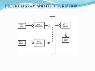
SlideShare a Scribd company logo
The fear of theft and burglary always annoys many people. When lock
and keys become less safe, one can seek the help of electronic security systems.
Such a portable security system is described here.
This electronic setup auto activated whenever the intruder enters to the
unauthorized no entry area. It auto activate the landline number and redial the last
dialed number from the conventional telephone. All we need is to do minor
changes to activate this telephone as it works as to become auto dialer circuit.
Thus whenever the intruder enters to the area, it activates the sensor circuit
of either sound activation or infrared light beam obstruction circuit, the redial
circuit become active and give a ring tone to the receiving end. It may be a mobile
phone or any landline phone or even police control room.
™CHAPTERCONTENTPAGE NO.
1. INTRODUCTION ………………………………………….. 3
1.1 Project Definition
1.2 Project Overview
2. BLOCKDIAGRAM AND ITS DESCRIPTION…………… 6
2.1Block Diagram Description:-
3. SCHEMATIC DIAGRAM & CIRCUIT DESCRIPTION……… 9
3.1. Transmission Circuit
3..2. R e c e i v e r C i r c u i t
4. LIST OF COMPONENTS………………………………….. 13
4.1. List of Components
5. DESCRIPTION OF COMPONENTS…………………………... 14
5.1 Description of Components
6. PROJECT FLOW CHART…………………………………… 21
7. FUTURE EXPANSION……………………………………. 33
8. APPLICATION, ADVANTAGES &DISADVANTAGES….. 33
1.1 Project Definition:-
Project title is “Automatic Room Light Controller With
Bidirectional Visitor Counter”.
The objective of this project is to make a controller based model to count
number of persons visiting particular room and accordingly light up the room.
Here we can use sensor and can know present number of persons.
In today’s world, there is a continuous need for automatic appliances.
With the increase in standard of living, there is a sense of urgency for
developing circuits that would ease the complexity of life.
Also if at all one wants to know the number of people present in room
soaps not to have congestion, this circuit proves to be helpful.
This project "automatic room light controller with visitor
counter using microcontroller" is a reliable circuit that takes over the task of
persons/visitor in the room very accurately. When somebody enters into the
room will be switched ON and when any one. The light in room will be only
switched OFF until all the persons in the room go out. The total number of
person inside the room also displayed on the seven segment displays. The
microcontroller does the above job. it receives the signals from the sencers, and
this signal is operated under the control of software which is stored in rom.
Micron roller AT89S52 continuously monitor the
infrared receivers, when any object pass through the IR rays falling on the
receivers are obstructed this obstruction is sensed by the microcontroller.
1.2Project Overview:-
This Project ―Automatic Room Light Controller with Visitor Counter
using Microcontroller is a reliable circuit that takes over the task of controlling the
room lights
as well us counting number of persons/ visitors in the room very accurately. When
somebody
enters into the room then the counter is incremented by one and the light in the room
will be
switched ON and when any one leaves the room then the counter is decremented by
one. The
light will be only switched OFF until all the persons in the room go out. The total
number of
persons inside the room is also displayed on the seven segment displays.
8
The microcontroller does the above job. It receives the signals from the sensors, and
this signal is operated under the control of software which is stored in ROM.
MicrocontrollerAT89S52 continuously monitor the Infrared Receivers, When any
object pass
through the IR Receiver's then the IR Rays falling on the receiver are obstructed , this
obstruction is sensed by the Microcontroller
2.2Block Diagram Description:-
The basic block diagram of the bidirectional visitor counter with automatic light
controller is
shown in the above figure. Mainly this block diagram consists of the following essential
blocks.
1. Power Supply
2. Entry and Exit sensor circuit
3. AT 89S52 micro-controller
4. Relay driver circuit
1. Power Supply:-
Here we used +12V and +5V dc power supply. The main function of this block is
to provide the required amount of voltage to essential circuits. +12voltage is given. +12V
is
given to relay driver. To get the +5V dc power supply we have used here IC 7805, which
provides the +5V dc regulated power supply.
2. Enter and Exit Circuits:-
This is one of the main parts of our project. The main intention of this block is to
sense the person. For sensing the person and light we are using the light dependent
register
(LDR). By using this sensor and its related circuit diagram we can count the persons.
3. 89S52 Microcontroller:-
It is a low-power, high performance CMOS 8-bit microcontroller with8KB of
Flash Programmable and Erasable Read Only Memory (PEROM). THE device is
manufactured using Atmel’s high-density nonvolatile memory technology and is
compatible with the MCS-51TMinstruction set and pin out. Theon-chip Flash allows the
program memory to be reprogrammed in-system or by a conventional nonvolatile
memory
programmer. By combining a versatile 8-bitCPU with Flash on a monolithic hip, the
Atmel
AT89S52 is a powerful.
4. Relay Driver Circuit:-
This block has the potential to drive the various controlled devices. In this block
mainly we are using the transistor and the relays. One relay driver circuit we are using to
control
the light. Output signal from AT89S52 is given to the base of the transistor, which we are
further energizing the particular relay. Because of this appropriate device is selected and
it do its
allotted function.
SCHEMATIC DIAGRAM &CIRCUIT DESCRIPTION
™CIRCUIT DESCRIPTION;-
¾ There are two main parts of the circuits.
™3.1.Transmission Circuit (Infrared LEDs)
™3.2. Receiver Circuit (Sensors)
This circuit diagram above shows:
a 555 timer IC, configured to function as a basic actable multivibrator.The stabl
emultivibratorgenerates squarewave, the period of which is determined by the circu
it external to IC 555. Theastable multivibrator does not require any external trigger
to change the stateof the output. Hence the name free running oscillator. The time
during whichthe output is either high or low is determined by the two resistors and
a capacitor which are externally connected to the 555 timer.
In this circuit, a negative pulse applied at pin 2 triggers an internal flip-flop that
turns
off pin 7's discharge transistor, allowing C1 to charge up throughR1. At the same time,
the flipflop brings the output (pin 3) level to 'high’. When capacitor C1 as charged up to
about 2/3 Vcc,
the flip-flop is triggered once again, this time making the pin 3 output 'low' and turning
on pin.
7's discharge transistor, which discharges C1 to ground. This circuit, in effect, produces a
pulseat pin 3 whose width t is just the product of R1 and C1, i.e., t=R1C1.
IR Transmission circuit is used to generate the modulated 36
kHz IR signal. The IC555 in the transmitter side is to generate 36 kHz
square wave. Adjust the preset in the transmitter to get a 38 kHz signal at the
o/p. Then you point it over the sensor and its o/p will go low when it senses the IR
signal of 38 kHz .
3.2 Receiver circuit:-
The IR transmitter will emit modulated 38 kHz IR signal and at the
receiver we use TSOP1738 (Infrared Sensor). The output
goes high when there is an interruption and it return back to low
after the time period determined by the capacitor and resistor in the
circuit i.e. around 1 second. CL100 is to trigger theIC555 which is
configured as monostable multivibrator. Input is given to the Port 1of the
microcontroller. Port 0 is used for the 7-Segment display purpose. Port 2 is used
for the Relay Turn On and Turn off Purpose.LTS 542 (Common Anode)
is used for 7-Segment display and that time Relay will get voltage and triggered,
so light will get voltage and it will turn on and when counter will be 00
and at that time Relay will be turned off. Reset button will reset the
microcontroller.
1. Microcontroller – AT89S52
2. IC – 7805
3. Sensor – TSOP 1738 (Infrared Sensor)
4. Transformer – 12-0-12, 500 mA
5. Preset – 4.7K
6. Disc capacitor – 104,33pF
7. Reset button switch
8. Rectifier diode – IN4148
9. Transistor – BC 547, 2N2222
10.-Segment Display
Description of Components1.Microcontroller AT89S52:-
The AT89S52 is a low-power, high-performance CMOS 8-bit
microcontroller with 8K bytes
of in-system programmable Flash memory. The device is
manufactured using Atmel’s highdensity nonvolatile memory
technology and is compatible with the Industry-standard 80C51
instruction set and pin out. The on-chip Flash allows the program
memory to be reprogrammed
in-system or by a conventional nonvolatile memory pro- grammar.
By combining a versatile
bit CPU with in-system programmable Flash on a monolithic chip,
the Atmel AT89S52 is a
powerful microcontroller which provides a highly-flexible and
cost-effective solution to many
embedded control applications.
1. 8 KB Reprogrammable flash.
2. 32 Programmable I/O lines.
3. 16 bit Timer/Counter—3.
4. 8 Interrupt sources.
5. Power range: 4V – 5.5V
6. Endurance : 1000 Writes / Erase cycles
7. Fully static operation: 0 Hz to 33 MHz
8. Three level program memory lock
9. Power off flag
10.Full duplex UART serial channel
11.Low power idle and power down modes
12.Interrupt recovery from power down modes
13.256 KB internal RAM
14. Dual data pointer
2.TSOP1738 (INFRARED SENSOR)
• Description:-
The TSOP17.. – Series are miniaturized receivers for infrared remote control systems.
PIN
diode and preamplifier are assembled on lead frame, the epoxy package is designed as
IR filter.
The demodulated output signal can directly be decoded by a microprocessor. TSOP17...
is the
standard IR remote control receiver series, supporting all major transmission codes.
• Features:-
1. Photo detector and preamplifier in one package
2. Internal filter for PCM frequency
3. Improved shielding against electrical field disturbance
4. TTL and CMOS compatibility
5. Output active low
6. Low power consumption
7. High immunity against ambient light
8. Continuous data transmission possible (up to 2400 bps)
3. 555 (TIMER IC):-
• Description:-
The LM555 is a highly stable device for generating accurate time
delays or oscillation. Additional terminals are provided for triggering or resetting if
desired. In the time delay mode of operation, the time is precisely controlled by
one external resistor and capacitor. For actable operation as an oscillator, the free
running frequency and duty cycle are accurately controlled with two external
resistors and one capacitor. The circuit may be triggered and reset on falling
waveforms, and the output circuit can source or sink up to 200mA or drive TTL
circuits
• Features:
1. Direct replacement for SE555/NE555
2. Timing from microseconds through hours
3. Operates in both as table and monostable modes
4. Adjustable duty cycle
5. Output can source or sink 200 mAOutput and supply TTL compatible
6. Temperature stability better than 0.005% per °C
7. Normally on and normally off output
8. Available in 8-pin MSOP package
• Applications:-
1. Precision timing
2. Pulse generation
3. Sequential timing
4. LTS 542 (7-Segment Display)Description:
The LTS 542 is a 0.52 inch digit height single digit seven-segment
display. This
device utilizes Hi-eff. Red LED chips, which are made from
GaAsPon Gap substrate, and has a
red face and red segment.
• Features:
1. Common Anode
2. 0.52 Inch Digit Height
3. Continuous Uniform Segments
4. Low power Requirement
5. Excellent Characters Appearance
5 .LM7805 (Voltage Regulator):-
• Description:-
The KA78XX/KA78XXA series of three-terminal positiveregulator are available in the
TO220/D-PAK package and with several fixedoutput voltages, making them useful in a
wide
range of applications. Each typeemploys internal current limiting, thermal shut down
and safe
operating areaprotection, making it essentially indestructible. If adequate heat sinking
isprovided, they can deliver over 1A output current. Although designed primarily as
fixed
voltage regulators, these devices can be used with external components toobtain
adjustable
voltages and currents.
• Features:-
1. Output Current up to 1A
2. Output Voltages of 5, 6, 8, 9, 10, 12, 15, 18, 24V
3. Thermal Overload Protection
4. Short Circuit Protection
• 6 .RELAY CIRCUIT:-
A single pole dabble throw (SPDT) relay is connected to port RB1 of the microcontroller
through a driver transistor. The relay requires 12 volts at a current of around 100ma,
which
cannot provide by the microcontroller. So the driver transistor is added. The relay is
used to
operate the external solenoid forming part of a locking device or for operating any
other
electrical devices. Normally there lay remains off. As soon as pin of the microcontroller
goes high, the relay operates. When the relay operates and releases. Diode D2 is the
standard diode one mechanical relay to prevent back EMF from damaging Q3 when the
relay releases.
PROJECT FLOW CHART
If the sensor 1 is interrupted first then the microcontroller will look for
the sensor 2, and if it is interrupted then the microcontroller will increment
the count and switch on the relay, if it is first time interrupted.
If the sensor 2 is interrupted first then the microcontroller will look for
the sensor 1, and if it is interrupted then the microcontroller will
decrement the count.
When the last person leaves the room then counter goes to 0 and that
time the relay will turn off, and light will be turned off.
1. By using this circuit and proper power supply we can implement various
applications Such as fans, tube lights, etc.
2. By modifying this circuit and using two relays we can achieve a task of
opening and closing the door.
Advantages:-
1. Low cost
2. Easy to use
3. Implement in single door
Disadvantages:-
1. It is used only when one single person cuts the rays of the sensor hence it cannot be
used when two
person cross simultaneously.
• Application:-
1. For counting purposes
2. For automatic room light control

More Related Content

What's hot

Microprocessor-Based Automatic Door Opener
Microprocessor-Based Automatic Door OpenerMicroprocessor-Based Automatic Door Opener
Microprocessor-Based Automatic Door Opener
Jitendra Choudhary
 
Manual heatit z-din 616_eng
Manual heatit z-din 616_engManual heatit z-din 616_eng
Manual heatit z-din 616_eng
Domotica daVinci
 
Remote controlling of home appliance by moniruzzaman iiuc
Remote controlling of home appliance by moniruzzaman iiuc Remote controlling of home appliance by moniruzzaman iiuc
Remote controlling of home appliance by moniruzzaman iiuc
Md Moneruzzman
 
TV Remote control Home Appliances using Arduino(Infrared)
TV Remote control Home Appliances using Arduino(Infrared)TV Remote control Home Appliances using Arduino(Infrared)
TV Remote control Home Appliances using Arduino(Infrared)
sushil roy thalakayala
 
Auto dial-er Home security
Auto dial-er Home securityAuto dial-er Home security
Auto dial-er Home securityvaibhav jindal
 
102642452 infrared-remote-switch-project-report
102642452 infrared-remote-switch-project-report102642452 infrared-remote-switch-project-report
102642452 infrared-remote-switch-project-reportisnadh
 
Remote Control Circuit.
Remote Control Circuit.Remote Control Circuit.
Remote Control Circuit.
Maruf Priyo
 
Ec2308 mini project
Ec2308 mini projectEc2308 mini project
Ec2308 mini projectunnimaya_k
 
Digital clock workshop
Digital clock workshopDigital clock workshop
Digital clock workshop
Kedarv
 
Infrared Remote Controlled Devices
Infrared Remote Controlled DevicesInfrared Remote Controlled Devices
Infrared Remote Controlled Devices
Narayan Jaiswal
 
universal remote controller for electric bulb and ceiling fan
universal remote controller for electric bulb and ceiling fanuniversal remote controller for electric bulb and ceiling fan
universal remote controller for electric bulb and ceiling fan
OGAGA OTOBOR
 
Digital clock presentation
Digital clock presentationDigital clock presentation
Digital clock presentation
Aditya Jha ✅
 
Automatic doorbell with object detection
Automatic doorbell with object detectionAutomatic doorbell with object detection
Automatic doorbell with object detection
Anurag Alaria
 
Implementation of an Improved Microcontroller Based Moving Message Display Sy...
Implementation of an Improved Microcontroller Based Moving Message Display Sy...Implementation of an Improved Microcontroller Based Moving Message Display Sy...
Implementation of an Improved Microcontroller Based Moving Message Display Sy...
IOSR Journals
 

What's hot (18)

Project ppt
Project pptProject ppt
Project ppt
 
Microprocessor-Based Automatic Door Opener
Microprocessor-Based Automatic Door OpenerMicroprocessor-Based Automatic Door Opener
Microprocessor-Based Automatic Door Opener
 
Manual heatit z-din 616_eng
Manual heatit z-din 616_engManual heatit z-din 616_eng
Manual heatit z-din 616_eng
 
Remote controlling of home appliance by moniruzzaman iiuc
Remote controlling of home appliance by moniruzzaman iiuc Remote controlling of home appliance by moniruzzaman iiuc
Remote controlling of home appliance by moniruzzaman iiuc
 
TV Remote control Home Appliances using Arduino(Infrared)
TV Remote control Home Appliances using Arduino(Infrared)TV Remote control Home Appliances using Arduino(Infrared)
TV Remote control Home Appliances using Arduino(Infrared)
 
Auto dial-er Home security
Auto dial-er Home securityAuto dial-er Home security
Auto dial-er Home security
 
102642452 infrared-remote-switch-project-report
102642452 infrared-remote-switch-project-report102642452 infrared-remote-switch-project-report
102642452 infrared-remote-switch-project-report
 
Remote Control Circuit.
Remote Control Circuit.Remote Control Circuit.
Remote Control Circuit.
 
Final report
Final reportFinal report
Final report
 
Ec2308 mini project
Ec2308 mini projectEc2308 mini project
Ec2308 mini project
 
Digital clock workshop
Digital clock workshopDigital clock workshop
Digital clock workshop
 
Infrared Remote Controlled Devices
Infrared Remote Controlled DevicesInfrared Remote Controlled Devices
Infrared Remote Controlled Devices
 
S123 b30u
S123 b30uS123 b30u
S123 b30u
 
universal remote controller for electric bulb and ceiling fan
universal remote controller for electric bulb and ceiling fanuniversal remote controller for electric bulb and ceiling fan
universal remote controller for electric bulb and ceiling fan
 
Digital clock presentation
Digital clock presentationDigital clock presentation
Digital clock presentation
 
Magnetic door lock
Magnetic door lockMagnetic door lock
Magnetic door lock
 
Automatic doorbell with object detection
Automatic doorbell with object detectionAutomatic doorbell with object detection
Automatic doorbell with object detection
 
Implementation of an Improved Microcontroller Based Moving Message Display Sy...
Implementation of an Improved Microcontroller Based Moving Message Display Sy...Implementation of an Improved Microcontroller Based Moving Message Display Sy...
Implementation of an Improved Microcontroller Based Moving Message Display Sy...
 

Similar to Atomatic light controller

Visiter counter doc
Visiter counter docVisiter counter doc
Visiter counter doc
Prem Kumar
 
INTERRUPT DRIVEN MULTIPLEXED 7 SEGMENT DIGITAL CLOCK
INTERRUPT DRIVEN MULTIPLEXED 7 SEGMENT DIGITAL CLOCKINTERRUPT DRIVEN MULTIPLEXED 7 SEGMENT DIGITAL CLOCK
INTERRUPT DRIVEN MULTIPLEXED 7 SEGMENT DIGITAL CLOCK
Santanu Chatterjee
 
AUTOMATIC WIRELESS POWER GRID CONTROL
AUTOMATIC WIRELESS POWER GRID CONTROLAUTOMATIC WIRELESS POWER GRID CONTROL
AUTOMATIC WIRELESS POWER GRID CONTROL
shiv kapil
 
56211728 automatic-room-light-controller-with-bidirectional-visitor-counter
56211728 automatic-room-light-controller-with-bidirectional-visitor-counter56211728 automatic-room-light-controller-with-bidirectional-visitor-counter
56211728 automatic-room-light-controller-with-bidirectional-visitor-counterAnn Francis Olita
 
Automatic room-light-controller-visitor-counter
Automatic room-light-controller-visitor-counterAutomatic room-light-controller-visitor-counter
Automatic room-light-controller-visitor-counterMohit Awasthi
 
ELECTRONICS PROJECT REPORT OF HOME AUTOMATION CUM BUILDING SECUIRITY
ELECTRONICS PROJECT REPORT OF HOME AUTOMATION CUM BUILDING SECUIRITYELECTRONICS PROJECT REPORT OF HOME AUTOMATION CUM BUILDING SECUIRITY
ELECTRONICS PROJECT REPORT OF HOME AUTOMATION CUM BUILDING SECUIRITY
Eldhose George
 
Automatic room light controller
Automatic room light controllerAutomatic room light controller
Automatic room light controller
MD Jannatul Giyem
 
Applications of microcontroller
Applications of microcontrollerApplications of microcontroller
Applications of microcontroller
babak danyal
 
3) Remote Controlled Fan Regulator
3) Remote Controlled Fan Regulator3) Remote Controlled Fan Regulator
3) Remote Controlled Fan Regulatorsajin sr
 
Gsm based garbage disposal
Gsm based garbage disposalGsm based garbage disposal
Gsm based garbage disposal
Suhanthi Devraj
 
Coin based mobile charger project report
Coin based mobile charger project reportCoin based mobile charger project report
Coin based mobile charger project report
kaushal chaubey
 
Automatic car parking system by Himanshu
Automatic car parking system by HimanshuAutomatic car parking system by Himanshu
Automatic car parking system by Himanshuhimanshu3070
 
INTELIGENT RAILWAY SYSTEM
INTELIGENT RAILWAY SYSTEMINTELIGENT RAILWAY SYSTEM
INTELIGENT RAILWAY SYSTEM
Ghanshyam Dusane
 
Dtmf based home appliance control
Dtmf based home appliance controlDtmf based home appliance control
Dtmf based home appliance control
Krishna Malhotra
 
Dtmf based home appliance control 2
Dtmf based home appliance control 2Dtmf based home appliance control 2
Dtmf based home appliance control 2Krish Karn
 
Dtmf based home appliance control(1)
Dtmf based home appliance control(1)Dtmf based home appliance control(1)
Dtmf based home appliance control(1)
Sanjay Kumar
 
Automatic room light controller using microcontroller and visitor counter
Automatic room light controller using microcontroller and visitor counterAutomatic room light controller using microcontroller and visitor counter
Automatic room light controller using microcontroller and visitor counter
eSAT Journals
 
ACCELEROMETER BASED GESTURE ROBO CAR
ACCELEROMETER BASED GESTURE ROBO CARACCELEROMETER BASED GESTURE ROBO CAR
ACCELEROMETER BASED GESTURE ROBO CAR
Harshit Jain
 
4 Way traffic controll new
4 Way traffic controll new4 Way traffic controll new
4 Way traffic controll newMainak Nandi
 

Similar to Atomatic light controller (20)

Visiter counter doc
Visiter counter docVisiter counter doc
Visiter counter doc
 
INTERRUPT DRIVEN MULTIPLEXED 7 SEGMENT DIGITAL CLOCK
INTERRUPT DRIVEN MULTIPLEXED 7 SEGMENT DIGITAL CLOCKINTERRUPT DRIVEN MULTIPLEXED 7 SEGMENT DIGITAL CLOCK
INTERRUPT DRIVEN MULTIPLEXED 7 SEGMENT DIGITAL CLOCK
 
AUTOMATIC WIRELESS POWER GRID CONTROL
AUTOMATIC WIRELESS POWER GRID CONTROLAUTOMATIC WIRELESS POWER GRID CONTROL
AUTOMATIC WIRELESS POWER GRID CONTROL
 
56211728 automatic-room-light-controller-with-bidirectional-visitor-counter
56211728 automatic-room-light-controller-with-bidirectional-visitor-counter56211728 automatic-room-light-controller-with-bidirectional-visitor-counter
56211728 automatic-room-light-controller-with-bidirectional-visitor-counter
 
Automatic room-light-controller-visitor-counter
Automatic room-light-controller-visitor-counterAutomatic room-light-controller-visitor-counter
Automatic room-light-controller-visitor-counter
 
ELECTRONICS PROJECT REPORT OF HOME AUTOMATION CUM BUILDING SECUIRITY
ELECTRONICS PROJECT REPORT OF HOME AUTOMATION CUM BUILDING SECUIRITYELECTRONICS PROJECT REPORT OF HOME AUTOMATION CUM BUILDING SECUIRITY
ELECTRONICS PROJECT REPORT OF HOME AUTOMATION CUM BUILDING SECUIRITY
 
Automatic room light controller
Automatic room light controllerAutomatic room light controller
Automatic room light controller
 
Applications of microcontroller
Applications of microcontrollerApplications of microcontroller
Applications of microcontroller
 
Project
ProjectProject
Project
 
3) Remote Controlled Fan Regulator
3) Remote Controlled Fan Regulator3) Remote Controlled Fan Regulator
3) Remote Controlled Fan Regulator
 
Gsm based garbage disposal
Gsm based garbage disposalGsm based garbage disposal
Gsm based garbage disposal
 
Coin based mobile charger project report
Coin based mobile charger project reportCoin based mobile charger project report
Coin based mobile charger project report
 
Automatic car parking system by Himanshu
Automatic car parking system by HimanshuAutomatic car parking system by Himanshu
Automatic car parking system by Himanshu
 
INTELIGENT RAILWAY SYSTEM
INTELIGENT RAILWAY SYSTEMINTELIGENT RAILWAY SYSTEM
INTELIGENT RAILWAY SYSTEM
 
Dtmf based home appliance control
Dtmf based home appliance controlDtmf based home appliance control
Dtmf based home appliance control
 
Dtmf based home appliance control 2
Dtmf based home appliance control 2Dtmf based home appliance control 2
Dtmf based home appliance control 2
 
Dtmf based home appliance control(1)
Dtmf based home appliance control(1)Dtmf based home appliance control(1)
Dtmf based home appliance control(1)
 
Automatic room light controller using microcontroller and visitor counter
Automatic room light controller using microcontroller and visitor counterAutomatic room light controller using microcontroller and visitor counter
Automatic room light controller using microcontroller and visitor counter
 
ACCELEROMETER BASED GESTURE ROBO CAR
ACCELEROMETER BASED GESTURE ROBO CARACCELEROMETER BASED GESTURE ROBO CAR
ACCELEROMETER BASED GESTURE ROBO CAR
 
4 Way traffic controll new
4 Way traffic controll new4 Way traffic controll new
4 Way traffic controll new
 

Recently uploaded

Honest Reviews of Tim Han LMA Course Program.pptx
Honest Reviews of Tim Han LMA Course Program.pptxHonest Reviews of Tim Han LMA Course Program.pptx
Honest Reviews of Tim Han LMA Course Program.pptx
timhan337
 
Sha'Carri Richardson Presentation 202345
Sha'Carri Richardson Presentation 202345Sha'Carri Richardson Presentation 202345
Sha'Carri Richardson Presentation 202345
beazzy04
 
Overview on Edible Vaccine: Pros & Cons with Mechanism
Overview on Edible Vaccine: Pros & Cons with MechanismOverview on Edible Vaccine: Pros & Cons with Mechanism
Overview on Edible Vaccine: Pros & Cons with Mechanism
DeeptiGupta154
 
June 3, 2024 Anti-Semitism Letter Sent to MIT President Kornbluth and MIT Cor...
June 3, 2024 Anti-Semitism Letter Sent to MIT President Kornbluth and MIT Cor...June 3, 2024 Anti-Semitism Letter Sent to MIT President Kornbluth and MIT Cor...
June 3, 2024 Anti-Semitism Letter Sent to MIT President Kornbluth and MIT Cor...
Levi Shapiro
 
How to Make a Field invisible in Odoo 17
How to Make a Field invisible in Odoo 17How to Make a Field invisible in Odoo 17
How to Make a Field invisible in Odoo 17
Celine George
 
Biological Screening of Herbal Drugs in detailed.
Biological Screening of Herbal Drugs in detailed.Biological Screening of Herbal Drugs in detailed.
Biological Screening of Herbal Drugs in detailed.
Ashokrao Mane college of Pharmacy Peth-Vadgaon
 
aaaaaaaaaaaaaaaaaaaaaaaaaaaaaaaaaaaaaaaaa
aaaaaaaaaaaaaaaaaaaaaaaaaaaaaaaaaaaaaaaaaaaaaaaaaaaaaaaaaaaaaaaaaaaaaaaaaaaaaaaaaa
aaaaaaaaaaaaaaaaaaaaaaaaaaaaaaaaaaaaaaaaa
siemaillard
 
CLASS 11 CBSE B.St Project AIDS TO TRADE - INSURANCE
CLASS 11 CBSE B.St Project AIDS TO TRADE - INSURANCECLASS 11 CBSE B.St Project AIDS TO TRADE - INSURANCE
CLASS 11 CBSE B.St Project AIDS TO TRADE - INSURANCE
BhavyaRajput3
 
Chapter 3 - Islamic Banking Products and Services.pptx
Chapter 3 - Islamic Banking Products and Services.pptxChapter 3 - Islamic Banking Products and Services.pptx
Chapter 3 - Islamic Banking Products and Services.pptx
Mohd Adib Abd Muin, Senior Lecturer at Universiti Utara Malaysia
 
Synthetic Fiber Construction in lab .pptx
Synthetic Fiber Construction in lab .pptxSynthetic Fiber Construction in lab .pptx
Synthetic Fiber Construction in lab .pptx
Pavel ( NSTU)
 
1.4 modern child centered education - mahatma gandhi-2.pptx
1.4 modern child centered education - mahatma gandhi-2.pptx1.4 modern child centered education - mahatma gandhi-2.pptx
1.4 modern child centered education - mahatma gandhi-2.pptx
JosvitaDsouza2
 
Operation Blue Star - Saka Neela Tara
Operation Blue Star   -  Saka Neela TaraOperation Blue Star   -  Saka Neela Tara
Operation Blue Star - Saka Neela Tara
Balvir Singh
 
Supporting (UKRI) OA monographs at Salford.pptx
Supporting (UKRI) OA monographs at Salford.pptxSupporting (UKRI) OA monographs at Salford.pptx
Supporting (UKRI) OA monographs at Salford.pptx
Jisc
 
Guidance_and_Counselling.pdf B.Ed. 4th Semester
Guidance_and_Counselling.pdf B.Ed. 4th SemesterGuidance_and_Counselling.pdf B.Ed. 4th Semester
Guidance_and_Counselling.pdf B.Ed. 4th Semester
Atul Kumar Singh
 
Instructions for Submissions thorugh G- Classroom.pptx
Instructions for Submissions thorugh G- Classroom.pptxInstructions for Submissions thorugh G- Classroom.pptx
Instructions for Submissions thorugh G- Classroom.pptx
Jheel Barad
 
Acetabularia Information For Class 9 .docx
Acetabularia Information For Class 9  .docxAcetabularia Information For Class 9  .docx
Acetabularia Information For Class 9 .docx
vaibhavrinwa19
 
Language Across the Curriculm LAC B.Ed.
Language Across the  Curriculm LAC B.Ed.Language Across the  Curriculm LAC B.Ed.
Language Across the Curriculm LAC B.Ed.
Atul Kumar Singh
 
Embracing GenAI - A Strategic Imperative
Embracing GenAI - A Strategic ImperativeEmbracing GenAI - A Strategic Imperative
Embracing GenAI - A Strategic Imperative
Peter Windle
 
678020731-Sumas-y-Restas-Para-Colorear.pdf
678020731-Sumas-y-Restas-Para-Colorear.pdf678020731-Sumas-y-Restas-Para-Colorear.pdf
678020731-Sumas-y-Restas-Para-Colorear.pdf
CarlosHernanMontoyab2
 
special B.ed 2nd year old paper_20240531.pdf
special B.ed 2nd year old paper_20240531.pdfspecial B.ed 2nd year old paper_20240531.pdf
special B.ed 2nd year old paper_20240531.pdf
Special education needs
 

Recently uploaded (20)

Honest Reviews of Tim Han LMA Course Program.pptx
Honest Reviews of Tim Han LMA Course Program.pptxHonest Reviews of Tim Han LMA Course Program.pptx
Honest Reviews of Tim Han LMA Course Program.pptx
 
Sha'Carri Richardson Presentation 202345
Sha'Carri Richardson Presentation 202345Sha'Carri Richardson Presentation 202345
Sha'Carri Richardson Presentation 202345
 
Overview on Edible Vaccine: Pros & Cons with Mechanism
Overview on Edible Vaccine: Pros & Cons with MechanismOverview on Edible Vaccine: Pros & Cons with Mechanism
Overview on Edible Vaccine: Pros & Cons with Mechanism
 
June 3, 2024 Anti-Semitism Letter Sent to MIT President Kornbluth and MIT Cor...
June 3, 2024 Anti-Semitism Letter Sent to MIT President Kornbluth and MIT Cor...June 3, 2024 Anti-Semitism Letter Sent to MIT President Kornbluth and MIT Cor...
June 3, 2024 Anti-Semitism Letter Sent to MIT President Kornbluth and MIT Cor...
 
How to Make a Field invisible in Odoo 17
How to Make a Field invisible in Odoo 17How to Make a Field invisible in Odoo 17
How to Make a Field invisible in Odoo 17
 
Biological Screening of Herbal Drugs in detailed.
Biological Screening of Herbal Drugs in detailed.Biological Screening of Herbal Drugs in detailed.
Biological Screening of Herbal Drugs in detailed.
 
aaaaaaaaaaaaaaaaaaaaaaaaaaaaaaaaaaaaaaaaa
aaaaaaaaaaaaaaaaaaaaaaaaaaaaaaaaaaaaaaaaaaaaaaaaaaaaaaaaaaaaaaaaaaaaaaaaaaaaaaaaaa
aaaaaaaaaaaaaaaaaaaaaaaaaaaaaaaaaaaaaaaaa
 
CLASS 11 CBSE B.St Project AIDS TO TRADE - INSURANCE
CLASS 11 CBSE B.St Project AIDS TO TRADE - INSURANCECLASS 11 CBSE B.St Project AIDS TO TRADE - INSURANCE
CLASS 11 CBSE B.St Project AIDS TO TRADE - INSURANCE
 
Chapter 3 - Islamic Banking Products and Services.pptx
Chapter 3 - Islamic Banking Products and Services.pptxChapter 3 - Islamic Banking Products and Services.pptx
Chapter 3 - Islamic Banking Products and Services.pptx
 
Synthetic Fiber Construction in lab .pptx
Synthetic Fiber Construction in lab .pptxSynthetic Fiber Construction in lab .pptx
Synthetic Fiber Construction in lab .pptx
 
1.4 modern child centered education - mahatma gandhi-2.pptx
1.4 modern child centered education - mahatma gandhi-2.pptx1.4 modern child centered education - mahatma gandhi-2.pptx
1.4 modern child centered education - mahatma gandhi-2.pptx
 
Operation Blue Star - Saka Neela Tara
Operation Blue Star   -  Saka Neela TaraOperation Blue Star   -  Saka Neela Tara
Operation Blue Star - Saka Neela Tara
 
Supporting (UKRI) OA monographs at Salford.pptx
Supporting (UKRI) OA monographs at Salford.pptxSupporting (UKRI) OA monographs at Salford.pptx
Supporting (UKRI) OA monographs at Salford.pptx
 
Guidance_and_Counselling.pdf B.Ed. 4th Semester
Guidance_and_Counselling.pdf B.Ed. 4th SemesterGuidance_and_Counselling.pdf B.Ed. 4th Semester
Guidance_and_Counselling.pdf B.Ed. 4th Semester
 
Instructions for Submissions thorugh G- Classroom.pptx
Instructions for Submissions thorugh G- Classroom.pptxInstructions for Submissions thorugh G- Classroom.pptx
Instructions for Submissions thorugh G- Classroom.pptx
 
Acetabularia Information For Class 9 .docx
Acetabularia Information For Class 9  .docxAcetabularia Information For Class 9  .docx
Acetabularia Information For Class 9 .docx
 
Language Across the Curriculm LAC B.Ed.
Language Across the  Curriculm LAC B.Ed.Language Across the  Curriculm LAC B.Ed.
Language Across the Curriculm LAC B.Ed.
 
Embracing GenAI - A Strategic Imperative
Embracing GenAI - A Strategic ImperativeEmbracing GenAI - A Strategic Imperative
Embracing GenAI - A Strategic Imperative
 
678020731-Sumas-y-Restas-Para-Colorear.pdf
678020731-Sumas-y-Restas-Para-Colorear.pdf678020731-Sumas-y-Restas-Para-Colorear.pdf
678020731-Sumas-y-Restas-Para-Colorear.pdf
 
special B.ed 2nd year old paper_20240531.pdf
special B.ed 2nd year old paper_20240531.pdfspecial B.ed 2nd year old paper_20240531.pdf
special B.ed 2nd year old paper_20240531.pdf
 

Atomatic light controller

  • 1.
  • 2. The fear of theft and burglary always annoys many people. When lock and keys become less safe, one can seek the help of electronic security systems. Such a portable security system is described here. This electronic setup auto activated whenever the intruder enters to the unauthorized no entry area. It auto activate the landline number and redial the last dialed number from the conventional telephone. All we need is to do minor changes to activate this telephone as it works as to become auto dialer circuit. Thus whenever the intruder enters to the area, it activates the sensor circuit of either sound activation or infrared light beam obstruction circuit, the redial circuit become active and give a ring tone to the receiving end. It may be a mobile phone or any landline phone or even police control room.
  • 3. ™CHAPTERCONTENTPAGE NO. 1. INTRODUCTION ………………………………………….. 3 1.1 Project Definition 1.2 Project Overview 2. BLOCKDIAGRAM AND ITS DESCRIPTION…………… 6 2.1Block Diagram Description:- 3. SCHEMATIC DIAGRAM & CIRCUIT DESCRIPTION……… 9 3.1. Transmission Circuit 3..2. R e c e i v e r C i r c u i t 4. LIST OF COMPONENTS………………………………….. 13 4.1. List of Components 5. DESCRIPTION OF COMPONENTS…………………………... 14 5.1 Description of Components 6. PROJECT FLOW CHART…………………………………… 21 7. FUTURE EXPANSION……………………………………. 33 8. APPLICATION, ADVANTAGES &DISADVANTAGES….. 33
  • 4. 1.1 Project Definition:- Project title is “Automatic Room Light Controller With Bidirectional Visitor Counter”. The objective of this project is to make a controller based model to count number of persons visiting particular room and accordingly light up the room. Here we can use sensor and can know present number of persons. In today’s world, there is a continuous need for automatic appliances. With the increase in standard of living, there is a sense of urgency for developing circuits that would ease the complexity of life. Also if at all one wants to know the number of people present in room soaps not to have congestion, this circuit proves to be helpful. This project "automatic room light controller with visitor counter using microcontroller" is a reliable circuit that takes over the task of persons/visitor in the room very accurately. When somebody enters into the room will be switched ON and when any one. The light in room will be only switched OFF until all the persons in the room go out. The total number of person inside the room also displayed on the seven segment displays. The microcontroller does the above job. it receives the signals from the sencers, and this signal is operated under the control of software which is stored in rom. Micron roller AT89S52 continuously monitor the infrared receivers, when any object pass through the IR rays falling on the receivers are obstructed this obstruction is sensed by the microcontroller.
  • 5. 1.2Project Overview:- This Project ―Automatic Room Light Controller with Visitor Counter using Microcontroller is a reliable circuit that takes over the task of controlling the room lights as well us counting number of persons/ visitors in the room very accurately. When somebody enters into the room then the counter is incremented by one and the light in the room will be switched ON and when any one leaves the room then the counter is decremented by one. The light will be only switched OFF until all the persons in the room go out. The total number of persons inside the room is also displayed on the seven segment displays. 8 The microcontroller does the above job. It receives the signals from the sensors, and this signal is operated under the control of software which is stored in ROM. MicrocontrollerAT89S52 continuously monitor the Infrared Receivers, When any object pass through the IR Receiver's then the IR Rays falling on the receiver are obstructed , this obstruction is sensed by the Microcontroller
  • 6.
  • 7. 2.2Block Diagram Description:- The basic block diagram of the bidirectional visitor counter with automatic light controller is shown in the above figure. Mainly this block diagram consists of the following essential blocks. 1. Power Supply 2. Entry and Exit sensor circuit 3. AT 89S52 micro-controller 4. Relay driver circuit 1. Power Supply:- Here we used +12V and +5V dc power supply. The main function of this block is to provide the required amount of voltage to essential circuits. +12voltage is given. +12V is given to relay driver. To get the +5V dc power supply we have used here IC 7805, which provides the +5V dc regulated power supply. 2. Enter and Exit Circuits:- This is one of the main parts of our project. The main intention of this block is to sense the person. For sensing the person and light we are using the light dependent register (LDR). By using this sensor and its related circuit diagram we can count the persons.
  • 8. 3. 89S52 Microcontroller:- It is a low-power, high performance CMOS 8-bit microcontroller with8KB of Flash Programmable and Erasable Read Only Memory (PEROM). THE device is manufactured using Atmel’s high-density nonvolatile memory technology and is compatible with the MCS-51TMinstruction set and pin out. Theon-chip Flash allows the program memory to be reprogrammed in-system or by a conventional nonvolatile memory programmer. By combining a versatile 8-bitCPU with Flash on a monolithic hip, the Atmel AT89S52 is a powerful. 4. Relay Driver Circuit:- This block has the potential to drive the various controlled devices. In this block mainly we are using the transistor and the relays. One relay driver circuit we are using to control the light. Output signal from AT89S52 is given to the base of the transistor, which we are further energizing the particular relay. Because of this appropriate device is selected and it do its allotted function.
  • 9. SCHEMATIC DIAGRAM &CIRCUIT DESCRIPTION ™CIRCUIT DESCRIPTION;- ¾ There are two main parts of the circuits. ™3.1.Transmission Circuit (Infrared LEDs) ™3.2. Receiver Circuit (Sensors)
  • 10. This circuit diagram above shows: a 555 timer IC, configured to function as a basic actable multivibrator.The stabl emultivibratorgenerates squarewave, the period of which is determined by the circu it external to IC 555. Theastable multivibrator does not require any external trigger to change the stateof the output. Hence the name free running oscillator. The time during whichthe output is either high or low is determined by the two resistors and a capacitor which are externally connected to the 555 timer. In this circuit, a negative pulse applied at pin 2 triggers an internal flip-flop that turns off pin 7's discharge transistor, allowing C1 to charge up throughR1. At the same time, the flipflop brings the output (pin 3) level to 'high’. When capacitor C1 as charged up to about 2/3 Vcc, the flip-flop is triggered once again, this time making the pin 3 output 'low' and turning on pin. 7's discharge transistor, which discharges C1 to ground. This circuit, in effect, produces a pulseat pin 3 whose width t is just the product of R1 and C1, i.e., t=R1C1. IR Transmission circuit is used to generate the modulated 36 kHz IR signal. The IC555 in the transmitter side is to generate 36 kHz square wave. Adjust the preset in the transmitter to get a 38 kHz signal at the o/p. Then you point it over the sensor and its o/p will go low when it senses the IR signal of 38 kHz .
  • 12. The IR transmitter will emit modulated 38 kHz IR signal and at the receiver we use TSOP1738 (Infrared Sensor). The output goes high when there is an interruption and it return back to low after the time period determined by the capacitor and resistor in the circuit i.e. around 1 second. CL100 is to trigger theIC555 which is configured as monostable multivibrator. Input is given to the Port 1of the microcontroller. Port 0 is used for the 7-Segment display purpose. Port 2 is used for the Relay Turn On and Turn off Purpose.LTS 542 (Common Anode) is used for 7-Segment display and that time Relay will get voltage and triggered, so light will get voltage and it will turn on and when counter will be 00 and at that time Relay will be turned off. Reset button will reset the microcontroller.
  • 13. 1. Microcontroller – AT89S52 2. IC – 7805 3. Sensor – TSOP 1738 (Infrared Sensor) 4. Transformer – 12-0-12, 500 mA 5. Preset – 4.7K 6. Disc capacitor – 104,33pF 7. Reset button switch 8. Rectifier diode – IN4148 9. Transistor – BC 547, 2N2222 10.-Segment Display
  • 14. Description of Components1.Microcontroller AT89S52:- The AT89S52 is a low-power, high-performance CMOS 8-bit microcontroller with 8K bytes of in-system programmable Flash memory. The device is manufactured using Atmel’s highdensity nonvolatile memory technology and is compatible with the Industry-standard 80C51 instruction set and pin out. The on-chip Flash allows the program memory to be reprogrammed in-system or by a conventional nonvolatile memory pro- grammar. By combining a versatile bit CPU with in-system programmable Flash on a monolithic chip, the Atmel AT89S52 is a powerful microcontroller which provides a highly-flexible and cost-effective solution to many embedded control applications.
  • 15. 1. 8 KB Reprogrammable flash. 2. 32 Programmable I/O lines. 3. 16 bit Timer/Counter—3. 4. 8 Interrupt sources. 5. Power range: 4V – 5.5V 6. Endurance : 1000 Writes / Erase cycles 7. Fully static operation: 0 Hz to 33 MHz 8. Three level program memory lock 9. Power off flag 10.Full duplex UART serial channel 11.Low power idle and power down modes 12.Interrupt recovery from power down modes 13.256 KB internal RAM 14. Dual data pointer
  • 16. 2.TSOP1738 (INFRARED SENSOR) • Description:- The TSOP17.. – Series are miniaturized receivers for infrared remote control systems. PIN diode and preamplifier are assembled on lead frame, the epoxy package is designed as IR filter. The demodulated output signal can directly be decoded by a microprocessor. TSOP17... is the standard IR remote control receiver series, supporting all major transmission codes. • Features:- 1. Photo detector and preamplifier in one package 2. Internal filter for PCM frequency 3. Improved shielding against electrical field disturbance 4. TTL and CMOS compatibility 5. Output active low 6. Low power consumption 7. High immunity against ambient light 8. Continuous data transmission possible (up to 2400 bps)
  • 17. 3. 555 (TIMER IC):- • Description:- The LM555 is a highly stable device for generating accurate time delays or oscillation. Additional terminals are provided for triggering or resetting if desired. In the time delay mode of operation, the time is precisely controlled by one external resistor and capacitor. For actable operation as an oscillator, the free running frequency and duty cycle are accurately controlled with two external resistors and one capacitor. The circuit may be triggered and reset on falling waveforms, and the output circuit can source or sink up to 200mA or drive TTL circuits • Features: 1. Direct replacement for SE555/NE555 2. Timing from microseconds through hours 3. Operates in both as table and monostable modes 4. Adjustable duty cycle 5. Output can source or sink 200 mAOutput and supply TTL compatible 6. Temperature stability better than 0.005% per °C 7. Normally on and normally off output 8. Available in 8-pin MSOP package
  • 18. • Applications:- 1. Precision timing 2. Pulse generation 3. Sequential timing 4. LTS 542 (7-Segment Display)Description: The LTS 542 is a 0.52 inch digit height single digit seven-segment display. This device utilizes Hi-eff. Red LED chips, which are made from GaAsPon Gap substrate, and has a red face and red segment. • Features: 1. Common Anode 2. 0.52 Inch Digit Height 3. Continuous Uniform Segments 4. Low power Requirement 5. Excellent Characters Appearance
  • 19. 5 .LM7805 (Voltage Regulator):- • Description:- The KA78XX/KA78XXA series of three-terminal positiveregulator are available in the TO220/D-PAK package and with several fixedoutput voltages, making them useful in a wide range of applications. Each typeemploys internal current limiting, thermal shut down and safe operating areaprotection, making it essentially indestructible. If adequate heat sinking isprovided, they can deliver over 1A output current. Although designed primarily as fixed voltage regulators, these devices can be used with external components toobtain adjustable voltages and currents. • Features:- 1. Output Current up to 1A 2. Output Voltages of 5, 6, 8, 9, 10, 12, 15, 18, 24V 3. Thermal Overload Protection 4. Short Circuit Protection
  • 20. • 6 .RELAY CIRCUIT:- A single pole dabble throw (SPDT) relay is connected to port RB1 of the microcontroller through a driver transistor. The relay requires 12 volts at a current of around 100ma, which cannot provide by the microcontroller. So the driver transistor is added. The relay is used to operate the external solenoid forming part of a locking device or for operating any other electrical devices. Normally there lay remains off. As soon as pin of the microcontroller goes high, the relay operates. When the relay operates and releases. Diode D2 is the standard diode one mechanical relay to prevent back EMF from damaging Q3 when the relay releases.
  • 22. If the sensor 1 is interrupted first then the microcontroller will look for the sensor 2, and if it is interrupted then the microcontroller will increment the count and switch on the relay, if it is first time interrupted. If the sensor 2 is interrupted first then the microcontroller will look for the sensor 1, and if it is interrupted then the microcontroller will decrement the count. When the last person leaves the room then counter goes to 0 and that time the relay will turn off, and light will be turned off.
  • 23. 1. By using this circuit and proper power supply we can implement various applications Such as fans, tube lights, etc. 2. By modifying this circuit and using two relays we can achieve a task of opening and closing the door. Advantages:- 1. Low cost 2. Easy to use 3. Implement in single door Disadvantages:- 1. It is used only when one single person cuts the rays of the sensor hence it cannot be used when two person cross simultaneously. • Application:- 1. For counting purposes 2. For automatic room light control