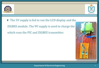
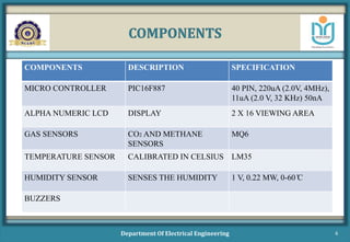
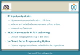
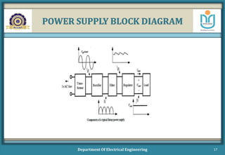
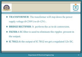
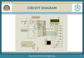
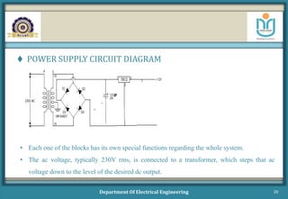
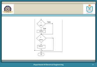
INTELLIGENT HELMET FOR COAL
MINERS
Department of Electrical Engineering
NEHRU COLLEGE OF ENGINEERING AND RESEARCH CENTRE
Pampady, Thiruvilwamala, Thrissur – 680 588, Kerala, INDIA
Group members Guided by
AKHIL KRISHNAN V (NCAMEEE011) Mr. ANOOP KUMAR MV
ARUN P S (NCAMEEE026) Asst. Professor,EEE Dept.
D YATHISHAN (NCAMEEE036)
JOMICE THOMAS (NCAMEEE051)
1
OBJECTIVE
 To provide greater security in coal mining, we are introducing a
new technology that can be incorporated in the helmet used by coal
miners which will act as “ INTELLIGENT HELMET FOR
COAL MINERS”.
Department Of Electrical Engineering 2
METHODOLOGY
 Our project consists of two sections transmitting end and
receiving end. The receiving end consists of power supply unit.
 Our group had completed the power supply unit which consists
of a bridge rectifier.
 Output of the bridge rectifier is fed to regulators 7805 and 7809
which gives an output voltage of 5V and 9V.
Department Of Electrical Engineering 3
 The 5V supply is fed to run the LCD display and the
ZIGBEE module. The 9V supply is used to charge the battery
which runs the PIC and ZIGBEE transmitter.
Department Of Electrical Engineering 4
BLOCK DIAGRAM
Department Of Electrical Engineering 5
COMPONENTS
Department Of Electrical Engineering 6
COMPONENTS DESCRIPTION SPECIFICATION
MICRO CONTROLLER PIC16F887 40 PIN, 220uA (2.0V, 4MHz),
11uA (2.0 V, 32 KHz) 50nA
ALPHA NUMERIC LCD DISPLAY 2 X 16 VIEWING AREA
GAS SENSORS CO2 AND METHANE
SENSORS
MQ6
TEMPERATURE SENSOR CALIBRATED IN CELSIUS LM35
HUMIDITY SENSOR SENSES THE HUMIDITY 1 V, 0.22 MW, 0-60 ̊C
BUZZERS
COMPONENTS DESCRIPTION
 The PIC16F887
It is one of the latest products from Microchip. It features all the components which
modern microcontrollers normally have. For its low price, wide range of application,
high quality and easy availability, it is an ideal solution in applications such as: the
control of different processes in industry, machine control devices, measurement of
different values etc. Some of its main features are listed below.
• RISC architecture
o Only 35 instructions to learn
o All single-cycle instructions except branches
• Operating frequency 0-20 MHz
Department Of Electrical Engineering 7
• Precision internal oscillator
o Factory calibrated
o Software selectable frequency of 4MHz
• Power supply voltage 2.0-5.5V
o Consumption: 220uA (2.0V, 4MHz), 11uA (2.0 V, 32 KHz) 50nA (stand-by
mode)
Department Of Electrical Engineering 8
• 33 input/output pins
o High current source/sink for direct LED drive
o software and individually programmable pull-up resistor
o Interrupt-on-Change pin
• 8K ROM memory in FLASH technology
o Chip can be reprogrammed up to 100 times
• In-Circuit Serial Programming Option
o Chip can be programmed even embedded in the target device
Department Of Electrical Engineering 9
• 256 bytes EEPROM memory
o Data can be written more than 1000 times
• 368 bytes RAM memory
• A/D converter:
o 14-channels
o 10-bit resolution
• 3 independent timers/counters
• Watch-dog timer
Department Of Electrical Engineering 10
• Analogue comparator module with
o Two analogue comparators
o Fixed voltage reference (0.6V)
o Programmable on-chip voltage reference
• PWM output steering control
• Enhanced USART module
Department Of Electrical Engineering 11
 2X16 ALPHA NUMERIC LCD
The LCD display line consists of two lines, 16 characters per line that is interfaced
to the PIC16F887.The display contains two thermal byte-wide registers, one for
commands (instruction) (RS=0) and the second for characters (data) to be displayed
(RS=1).It also contains a user-programmed RAM area that can be programmed to
generate any desired character that can be formed using a dot matrix. To distinguish
between these two data, the hex command byte 80 will be used to signify that the
display RAM address 00h will be chosen port1is used to furnish the command and
ports 3.2 to 3.4 furnish register select and read/write levels
Department Of Electrical Engineering 12
 GAS SENSOR
Gas sensor is a device that detects the presence of gases like carbon
monoxide, methane and other toxic gases and if exceeds the threshold
limit produces an alarm through the buzzer. The common types of gas
sensor are:
 Ionization gas sensor MQ6
 Photoelectric gas sensor
Photoelectric gas sensors are faster in detecting smoldering fires.
Ionization gas sensors are better at detecting the flaming fires.
Department Of Electrical Engineering 13
 TEMPERATURE SENSORS
The LM35 series are precision integrated-circuit temperature sensors,
whose output voltage is linearly proportional to the Celsius
(centigrade) temperature. The LM35 thus has an advantage over linear
temperature sensors calibrated in Kelvin, as the user is not required to
subtract a large constant voltage from its output to obtain convenient
scaling. The LM35 does not require any external calibration of
trimming to provide typical accuracies of ±1/40C at room temperature
and ±3/40C over a full -55 to -150C temperature range.
Department Of Electrical Engineering 14
 HUMIDITY SENSOR
Humidity sensors are gaining more significance in diverse areas of
measurement and controlling technology. The amount of the
water present in the air is nothing but the humidity. Humidity
sensor used is SHT21.
Department Of Electrical Engineering 15
 BUZZER
It is a signaling device, usually electronic, typically used in
automobiles. It mostly consists of a number of switches or sensors
connected to a control unit. These buzzers are available in
lightweight compact sizes ranging from the smallest diameter of
12mm to large Piezo electric sounders. Today piezoelectric sound
components are used in home appliances, audio equipment etc.
Department Of Electrical Engineering 16
POWER SUPPLY BLOCK DIAGRAM
Department Of Electrical Engineering 17
 TRANSFORMER: The transformer will step down the power
supply voltage (0-230V) to (0-12V) .
 BRIDGE RECTIFIER: It perform the ac to dc conversion.
 FILTER:A RC filter is used to eliminate the ripples present in
the output.
 IC 7812:At the output of IC 7812 we get a regulated 12v DC.
Department Of Electrical Engineering 18
CIRCUIT DIAGRAM
Department Of Electrical Engineering 19
RA0/AN0
2
RA1/AN1
3
RA2/AN2/VREF-/CVREF
4
RA4/T0CKI/C1OUT
6
RA5/AN4/SS/C2OUT
7
RE0/AN5/RD
8
RE1/AN6/WR
9
RE2/AN7/CS
10
OSC1/CLKIN
13
OSC2/CLKOUT
14
RC1/T1OSI/CCP2
16
RC2/CCP1
17
RC3/SCK/SCL
18
RD0/PSP0
19
RD1/PSP1
20
RB7/PGD
40
RB6/PGC
39
RB5
38
RB4
37
RB3/PGM
36
RB2
35
RB1
34
RB0/INT
33
RD7/PSP7
30
RD6/PSP6
29
RD5/PSP5
28
RD4/PSP4
27
RD3/PSP3
22
RD2/PSP2
21
RC7/RX/DT
26
RC6/TX/CK
25
RC5/SDO
24
RC4/SDI/SDA
23
RA3/AN3/VREF+
5
RC0/T1OSO/T1CKI
15
MCLR/Vpp/THV
1
U2
PIC16F877A
D7
14
D6
13
D5
12
D4
11
D3
10
D2
9
D1
8
D0
7
E
6
RW
5
RS
4
VSS
1
VDD
2
VEE
3
LCD2
LM016L
X1
CRYSTAL
C1
22pF
C2
22pF
RA0/AN0
2
RA1/AN1
3
RA2/AN2/VREF-/CVREF
4
RA4/T0CKI/C1OUT
6
RA5/AN4/SS/C2OUT
7
RE0/AN5/RD
8
RE1/AN6/WR
9
RE2/AN7/CS
10
OSC1/CLKIN
13
OSC2/CLKOUT
14
RC1/T1OSI/CCP2
16
RC2/CCP1
17
RC3/SCK/SCL
18
RD0/PSP0
19
RD1/PSP1
20
RB7/PGD
40
RB6/PGC
39
RB5
38
RB4
37
RB3/PGM
36
RB2
35
RB1
34
RB0/INT
33
RD7/PSP7
30
RD6/PSP6
29
RD5/PSP5
28
RD4/PSP4
27
RD3/PSP3
22
RD2/PSP2
21
RC7/RX/DT
26
RC6/TX/CK
25
RC5/SDO
24
RC4/SDI/SDA
23
RA3/AN3/VREF+
5
RC0/T1OSO/T1CKI
15
MCLR/Vpp/THV
1
U2
PIC16F877A
D7
14
D6
13
D5
12
D4
11
D3
10
D2
9
D1
8
D0
7
E
6
RW
5
RS
4
VSS
1
VDD
2
VEE
3
LCD2
LM016L
5 v
R1
10k
RESET
X1
4 MHz
C1
22pF
C2
22pF
VI
1
VO
3
GND
2
U2
7805
5vDC
50%
TEMPERATURESENSOR
10k
HUMIDITY SENSOR
R2
10k
R3
10k
R4
10k
R5
10k
R6
10k
R7
10k
R8
10k
R9
10k
R10
10k
R11
10k
BATTERY
GAS SENSOR
RXD
RTS
TXD
CTS
ZIGBEE
 POWER SUPPLY CIRCUIT DIAGRAM
Department Of Electrical Engineering 20
• Each one of the blocks has its own special functions regarding the whole system.
• The ac voltage, typically 230V rms, is connected to a transformer, which steps that ac
voltage down to the level of the desired dc output.
 A diode rectifier then provides a full-wave rectified voltage that
is initially filtered by a simple capacitor filter to produce a dc
voltage.
 This resulting dc voltage usually has some ripple or ac voltage
variation.
 IC 7812 voltage regulator circuit removes the ripples and also
remains the same dc value even if the input dc voltage varies, or
the load connected to the output dc voltage changes.
Department Of Electrical Engineering 21
FLOW CHART
Department Of Electrical Engineering 22
Department Of Electrical Engineering 23
THANK YOU!!!!
Department Of Electrical Engineering 24

INTELLIGENT HELMET FOR COAL MINERS

  • 1.
    INTELLIGENT HELMET FORCOAL MINERS Department of Electrical Engineering NEHRU COLLEGE OF ENGINEERING AND RESEARCH CENTRE Pampady, Thiruvilwamala, Thrissur – 680 588, Kerala, INDIA Group members Guided by AKHIL KRISHNAN V (NCAMEEE011) Mr. ANOOP KUMAR MV ARUN P S (NCAMEEE026) Asst. Professor,EEE Dept. D YATHISHAN (NCAMEEE036) JOMICE THOMAS (NCAMEEE051) 1
  • 2.
    OBJECTIVE  To providegreater security in coal mining, we are introducing a new technology that can be incorporated in the helmet used by coal miners which will act as “ INTELLIGENT HELMET FOR COAL MINERS”. Department Of Electrical Engineering 2
  • 3.
    METHODOLOGY  Our projectconsists of two sections transmitting end and receiving end. The receiving end consists of power supply unit.  Our group had completed the power supply unit which consists of a bridge rectifier.  Output of the bridge rectifier is fed to regulators 7805 and 7809 which gives an output voltage of 5V and 9V. Department Of Electrical Engineering 3
  • 4.
     The 5Vsupply is fed to run the LCD display and the ZIGBEE module. The 9V supply is used to charge the battery which runs the PIC and ZIGBEE transmitter. Department Of Electrical Engineering 4
  • 5.
    BLOCK DIAGRAM Department OfElectrical Engineering 5
  • 6.
    COMPONENTS Department Of ElectricalEngineering 6 COMPONENTS DESCRIPTION SPECIFICATION MICRO CONTROLLER PIC16F887 40 PIN, 220uA (2.0V, 4MHz), 11uA (2.0 V, 32 KHz) 50nA ALPHA NUMERIC LCD DISPLAY 2 X 16 VIEWING AREA GAS SENSORS CO2 AND METHANE SENSORS MQ6 TEMPERATURE SENSOR CALIBRATED IN CELSIUS LM35 HUMIDITY SENSOR SENSES THE HUMIDITY 1 V, 0.22 MW, 0-60 ̊C BUZZERS
  • 7.
    COMPONENTS DESCRIPTION  ThePIC16F887 It is one of the latest products from Microchip. It features all the components which modern microcontrollers normally have. For its low price, wide range of application, high quality and easy availability, it is an ideal solution in applications such as: the control of different processes in industry, machine control devices, measurement of different values etc. Some of its main features are listed below. • RISC architecture o Only 35 instructions to learn o All single-cycle instructions except branches • Operating frequency 0-20 MHz Department Of Electrical Engineering 7
  • 8.
    • Precision internaloscillator o Factory calibrated o Software selectable frequency of 4MHz • Power supply voltage 2.0-5.5V o Consumption: 220uA (2.0V, 4MHz), 11uA (2.0 V, 32 KHz) 50nA (stand-by mode) Department Of Electrical Engineering 8
  • 9.
    • 33 input/outputpins o High current source/sink for direct LED drive o software and individually programmable pull-up resistor o Interrupt-on-Change pin • 8K ROM memory in FLASH technology o Chip can be reprogrammed up to 100 times • In-Circuit Serial Programming Option o Chip can be programmed even embedded in the target device Department Of Electrical Engineering 9
  • 10.
    • 256 bytesEEPROM memory o Data can be written more than 1000 times • 368 bytes RAM memory • A/D converter: o 14-channels o 10-bit resolution • 3 independent timers/counters • Watch-dog timer Department Of Electrical Engineering 10
  • 11.
    • Analogue comparatormodule with o Two analogue comparators o Fixed voltage reference (0.6V) o Programmable on-chip voltage reference • PWM output steering control • Enhanced USART module Department Of Electrical Engineering 11
  • 12.
     2X16 ALPHANUMERIC LCD The LCD display line consists of two lines, 16 characters per line that is interfaced to the PIC16F887.The display contains two thermal byte-wide registers, one for commands (instruction) (RS=0) and the second for characters (data) to be displayed (RS=1).It also contains a user-programmed RAM area that can be programmed to generate any desired character that can be formed using a dot matrix. To distinguish between these two data, the hex command byte 80 will be used to signify that the display RAM address 00h will be chosen port1is used to furnish the command and ports 3.2 to 3.4 furnish register select and read/write levels Department Of Electrical Engineering 12
  • 13.
     GAS SENSOR Gassensor is a device that detects the presence of gases like carbon monoxide, methane and other toxic gases and if exceeds the threshold limit produces an alarm through the buzzer. The common types of gas sensor are:  Ionization gas sensor MQ6  Photoelectric gas sensor Photoelectric gas sensors are faster in detecting smoldering fires. Ionization gas sensors are better at detecting the flaming fires. Department Of Electrical Engineering 13
  • 14.
     TEMPERATURE SENSORS TheLM35 series are precision integrated-circuit temperature sensors, whose output voltage is linearly proportional to the Celsius (centigrade) temperature. The LM35 thus has an advantage over linear temperature sensors calibrated in Kelvin, as the user is not required to subtract a large constant voltage from its output to obtain convenient scaling. The LM35 does not require any external calibration of trimming to provide typical accuracies of ±1/40C at room temperature and ±3/40C over a full -55 to -150C temperature range. Department Of Electrical Engineering 14
  • 15.
     HUMIDITY SENSOR Humiditysensors are gaining more significance in diverse areas of measurement and controlling technology. The amount of the water present in the air is nothing but the humidity. Humidity sensor used is SHT21. Department Of Electrical Engineering 15
  • 16.
     BUZZER It isa signaling device, usually electronic, typically used in automobiles. It mostly consists of a number of switches or sensors connected to a control unit. These buzzers are available in lightweight compact sizes ranging from the smallest diameter of 12mm to large Piezo electric sounders. Today piezoelectric sound components are used in home appliances, audio equipment etc. Department Of Electrical Engineering 16
  • 17.
    POWER SUPPLY BLOCKDIAGRAM Department Of Electrical Engineering 17
  • 18.
     TRANSFORMER: Thetransformer will step down the power supply voltage (0-230V) to (0-12V) .  BRIDGE RECTIFIER: It perform the ac to dc conversion.  FILTER:A RC filter is used to eliminate the ripples present in the output.  IC 7812:At the output of IC 7812 we get a regulated 12v DC. Department Of Electrical Engineering 18
  • 19.
    CIRCUIT DIAGRAM Department OfElectrical Engineering 19 RA0/AN0 2 RA1/AN1 3 RA2/AN2/VREF-/CVREF 4 RA4/T0CKI/C1OUT 6 RA5/AN4/SS/C2OUT 7 RE0/AN5/RD 8 RE1/AN6/WR 9 RE2/AN7/CS 10 OSC1/CLKIN 13 OSC2/CLKOUT 14 RC1/T1OSI/CCP2 16 RC2/CCP1 17 RC3/SCK/SCL 18 RD0/PSP0 19 RD1/PSP1 20 RB7/PGD 40 RB6/PGC 39 RB5 38 RB4 37 RB3/PGM 36 RB2 35 RB1 34 RB0/INT 33 RD7/PSP7 30 RD6/PSP6 29 RD5/PSP5 28 RD4/PSP4 27 RD3/PSP3 22 RD2/PSP2 21 RC7/RX/DT 26 RC6/TX/CK 25 RC5/SDO 24 RC4/SDI/SDA 23 RA3/AN3/VREF+ 5 RC0/T1OSO/T1CKI 15 MCLR/Vpp/THV 1 U2 PIC16F877A D7 14 D6 13 D5 12 D4 11 D3 10 D2 9 D1 8 D0 7 E 6 RW 5 RS 4 VSS 1 VDD 2 VEE 3 LCD2 LM016L X1 CRYSTAL C1 22pF C2 22pF RA0/AN0 2 RA1/AN1 3 RA2/AN2/VREF-/CVREF 4 RA4/T0CKI/C1OUT 6 RA5/AN4/SS/C2OUT 7 RE0/AN5/RD 8 RE1/AN6/WR 9 RE2/AN7/CS 10 OSC1/CLKIN 13 OSC2/CLKOUT 14 RC1/T1OSI/CCP2 16 RC2/CCP1 17 RC3/SCK/SCL 18 RD0/PSP0 19 RD1/PSP1 20 RB7/PGD 40 RB6/PGC 39 RB5 38 RB4 37 RB3/PGM 36 RB2 35 RB1 34 RB0/INT 33 RD7/PSP7 30 RD6/PSP6 29 RD5/PSP5 28 RD4/PSP4 27 RD3/PSP3 22 RD2/PSP2 21 RC7/RX/DT 26 RC6/TX/CK 25 RC5/SDO 24 RC4/SDI/SDA 23 RA3/AN3/VREF+ 5 RC0/T1OSO/T1CKI 15 MCLR/Vpp/THV 1 U2 PIC16F877A D7 14 D6 13 D5 12 D4 11 D3 10 D2 9 D1 8 D0 7 E 6 RW 5 RS 4 VSS 1 VDD 2 VEE 3 LCD2 LM016L 5 v R1 10k RESET X1 4 MHz C1 22pF C2 22pF VI 1 VO 3 GND 2 U2 7805 5vDC 50% TEMPERATURESENSOR 10k HUMIDITY SENSOR R2 10k R3 10k R4 10k R5 10k R6 10k R7 10k R8 10k R9 10k R10 10k R11 10k BATTERY GAS SENSOR RXD RTS TXD CTS ZIGBEE
  • 20.
     POWER SUPPLYCIRCUIT DIAGRAM Department Of Electrical Engineering 20 • Each one of the blocks has its own special functions regarding the whole system. • The ac voltage, typically 230V rms, is connected to a transformer, which steps that ac voltage down to the level of the desired dc output.
  • 21.
     A dioderectifier then provides a full-wave rectified voltage that is initially filtered by a simple capacitor filter to produce a dc voltage.  This resulting dc voltage usually has some ripple or ac voltage variation.  IC 7812 voltage regulator circuit removes the ripples and also remains the same dc value even if the input dc voltage varies, or the load connected to the output dc voltage changes. Department Of Electrical Engineering 21
  • 22.
    FLOW CHART Department OfElectrical Engineering 22
  • 23.
  • 24.
    THANK YOU!!!! Department OfElectrical Engineering 24