Downloaded 1,816 times

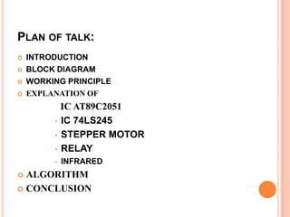
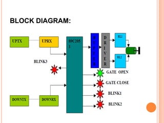
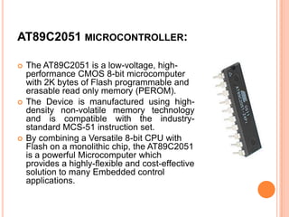
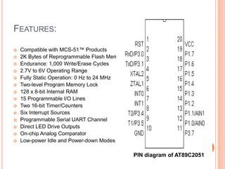
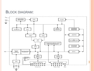

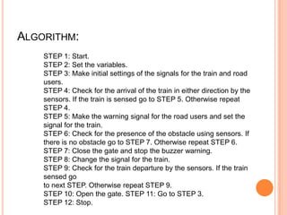
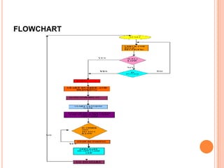

This document summarizes a seminar presentation on automatic rail gate control. It includes a plan of talk covering introduction, block diagram, working principle, explanation of components like the AT89C2051 and 74LS245 microcontrollers and a stepper motor, algorithm, and conclusion. The system uses sensors to detect approaching trains and control gates and warning signals to safely direct road traffic until the train passes through. It aims to reduce accidents by automating operations previously done manually.