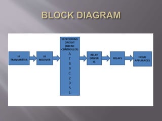
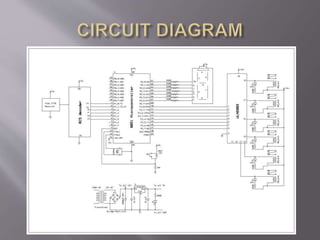
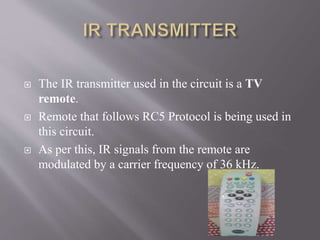
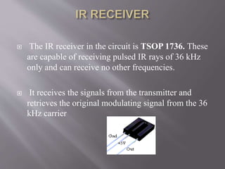
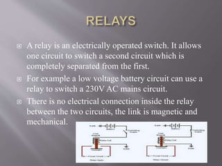
Submitted by:
Arpit Singh
Anuj Tiwari
Ambar Gupta
EC-A
 INTRODUCTION
 BLOCK DIAGRAM
 CIRCUIT DIAGRAM
 CIRCUIT DESCRIPTION
 REQUIREMENTS
 APPLICATIONS
 ADVANTAGES
 The aim of this project is to design a circuit
such that one can control home or industrial
appliances using the help of remote.
 Home Appliance Control System accessed by
TV remote to allow a home members to
control, monitor and coordinate home
appliances.
 This circuit can be operated upto a distance of
5-10 metres depending upon the remote which
we use.
 Step-down transformer
 Voltage regulator Ics
 Capacitors(electrolytic(1000uf,220uf) and ceramic(.01uf))
 Resistors (330ohm, 10k,1k)
 Diodes, LEDs , seven segment display
 Connecting wires, Reset Pin
 Crystal oscillator(11.09mhz, 12 mhz)
 Tv remote, IR receiver( IRX1 TSOP1738), IR decoder
 Microcontroller (AT89C2051)
 Relay Driver IC( ULN 2803)
 6 Relays, Sockets
 Software used BASCOM IDE
 UNIVERSAL PROGRAMMER
 Appliances
 The IR transmitter used in the circuit is a TV
remote.
 Remote that follows RC5 Protocol is being used in
this circuit.
 As per this, IR signals from the remote are
modulated by a carrier frequency of 36 kHz.
 The IR receiver in the circuit is TSOP 1736. These
are capable of receiving pulsed IR rays of 36 kHz
only and can receive no other frequencies.
 It receives the signals from the transmitter and
retrieves the original modulating signal from the 36
kHz carrier
 The microcontroller AT89C2051 is used as the IR
decoder in the circuit.
 It is flashed with a program that decodes the RC5
Protocol.
 It is designed to control the inputs and outputs. The
demodulated output from the receiver will be sensed
and decoded using this microcontroller.
 Thus it helps to determine which device is being
operated by the user.
 The RC-5 protocol was developed by Philips in the
late 1980s as a semi-proprietary consumer IR
(infrared) remote control communication protocol
for consumer electronics.
 The advantage of the RC-5 protocol is that (when
properly followed) any CD handset (for example)
may be used to control any brand of CD player
using the RC-5 protocol.
 IC ULN2803 consists of octal high voltage, high current
Darlington transistor arrays. The eight NPN Darlington
connected transistors in this family of arrays are ideally
suited for interfacing between low logic level digital
circuitry (such as TTL, CMOS or PMOS/NMOS) and
the higher current/voltage requirements of lamps, relays
etc.
 The main features ofULN2803 are:
 Eight Darlington’s with Common Emitter.
 Open–collector outputs.
 Output Current to 500 mA.
 Output Voltage to 50 V.
 A relay is an electrically operated switch. It allows
one circuit to switch a second circuit which is
completely separated from the first.
 For example a low voltage battery circuit can use a
relay to switch a 230V AC mains circuit.
 There is no electrical connection inside the relay
between the two circuits, the link is magnetic and
mechanical.
 Portable and easy to use.
 Simple in construction.
 Easy to maintain and repair.
 Efficient and low cost design.
 Low power consumption.
 This system can be used in industrial applications
 This system reduces human efforts and makes life a bit
easy without compromising on the efficiency of
appliances.
 Using this system one can also save time.
 The circuit can be modified to control all functions
of a particular device like the TV remote controlling
all processes of a television.
 Also the program can be altered to control the
ON/OFF processes of more than SIX appliances.
 Hereby we come to an end of or project “remote
controlling of home appliances”. This project
gives us an idea of RC5 Protocol and the
microcontroller AT89C2051.
 This project can be used anywhere either at home
or offices.
 This is also cost efficient. Thus by this attempt of
ours the ON/OFF processes of many devices was
successfully carried out by just using a TV remote.
CONTROLLING HOME APPLIANCES USING REMOTE(1)

CONTROLLING HOME APPLIANCES USING REMOTE(1)

  • 2.
    Submitted by: Arpit Singh AnujTiwari Ambar Gupta EC-A
  • 3.
     INTRODUCTION  BLOCKDIAGRAM  CIRCUIT DIAGRAM  CIRCUIT DESCRIPTION  REQUIREMENTS  APPLICATIONS  ADVANTAGES
  • 4.
     The aimof this project is to design a circuit such that one can control home or industrial appliances using the help of remote.  Home Appliance Control System accessed by TV remote to allow a home members to control, monitor and coordinate home appliances.  This circuit can be operated upto a distance of 5-10 metres depending upon the remote which we use.
  • 7.
     Step-down transformer Voltage regulator Ics  Capacitors(electrolytic(1000uf,220uf) and ceramic(.01uf))  Resistors (330ohm, 10k,1k)  Diodes, LEDs , seven segment display  Connecting wires, Reset Pin  Crystal oscillator(11.09mhz, 12 mhz)  Tv remote, IR receiver( IRX1 TSOP1738), IR decoder  Microcontroller (AT89C2051)  Relay Driver IC( ULN 2803)  6 Relays, Sockets  Software used BASCOM IDE  UNIVERSAL PROGRAMMER  Appliances
  • 9.
     The IRtransmitter used in the circuit is a TV remote.  Remote that follows RC5 Protocol is being used in this circuit.  As per this, IR signals from the remote are modulated by a carrier frequency of 36 kHz.
  • 10.
     The IRreceiver in the circuit is TSOP 1736. These are capable of receiving pulsed IR rays of 36 kHz only and can receive no other frequencies.  It receives the signals from the transmitter and retrieves the original modulating signal from the 36 kHz carrier
  • 11.
     The microcontrollerAT89C2051 is used as the IR decoder in the circuit.  It is flashed with a program that decodes the RC5 Protocol.  It is designed to control the inputs and outputs. The demodulated output from the receiver will be sensed and decoded using this microcontroller.  Thus it helps to determine which device is being operated by the user.
  • 12.
     The RC-5protocol was developed by Philips in the late 1980s as a semi-proprietary consumer IR (infrared) remote control communication protocol for consumer electronics.  The advantage of the RC-5 protocol is that (when properly followed) any CD handset (for example) may be used to control any brand of CD player using the RC-5 protocol.
  • 13.
     IC ULN2803consists of octal high voltage, high current Darlington transistor arrays. The eight NPN Darlington connected transistors in this family of arrays are ideally suited for interfacing between low logic level digital circuitry (such as TTL, CMOS or PMOS/NMOS) and the higher current/voltage requirements of lamps, relays etc.  The main features ofULN2803 are:  Eight Darlington’s with Common Emitter.  Open–collector outputs.  Output Current to 500 mA.  Output Voltage to 50 V.
  • 14.
     A relayis an electrically operated switch. It allows one circuit to switch a second circuit which is completely separated from the first.  For example a low voltage battery circuit can use a relay to switch a 230V AC mains circuit.  There is no electrical connection inside the relay between the two circuits, the link is magnetic and mechanical.
  • 15.
     Portable andeasy to use.  Simple in construction.  Easy to maintain and repair.  Efficient and low cost design.  Low power consumption.
  • 16.
     This systemcan be used in industrial applications  This system reduces human efforts and makes life a bit easy without compromising on the efficiency of appliances.  Using this system one can also save time.
  • 17.
     The circuitcan be modified to control all functions of a particular device like the TV remote controlling all processes of a television.  Also the program can be altered to control the ON/OFF processes of more than SIX appliances.
  • 19.
     Hereby wecome to an end of or project “remote controlling of home appliances”. This project gives us an idea of RC5 Protocol and the microcontroller AT89C2051.  This project can be used anywhere either at home or offices.  This is also cost efficient. Thus by this attempt of ours the ON/OFF processes of many devices was successfully carried out by just using a TV remote.