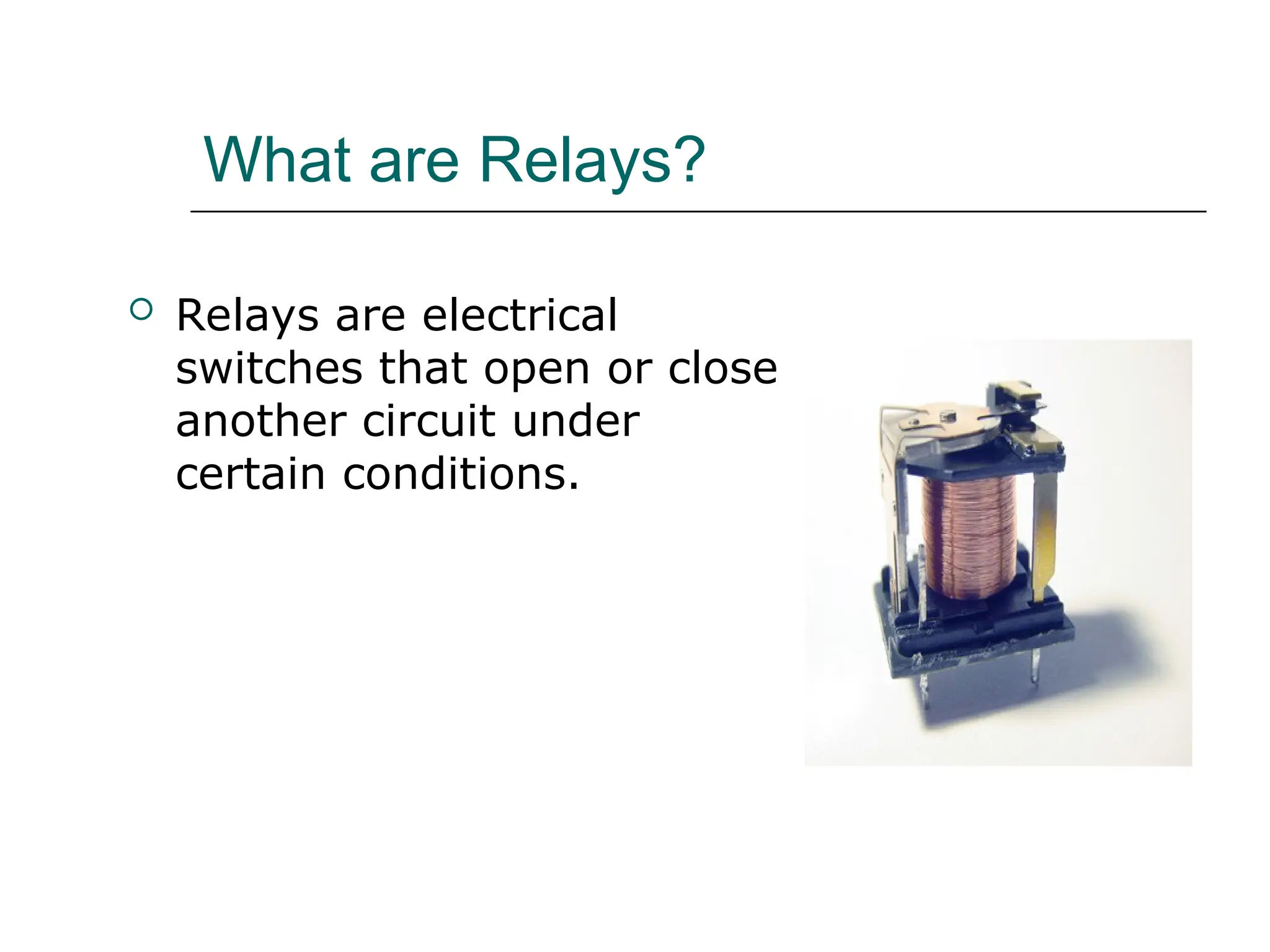
Protection and Relay Schemes
Chris Fraser
Amanda Chen Wang
Group#4
October 5, 2005
Agenda
 Introduction of Protective Relays
 Electrical System Protection with
Protective Relays
 Conclusion
What are Relays?
 Relays are electrical
switches that open or close
another circuit under
certain conditions.
Relay Purpose
 Isolate controlling circuit from controlled circuit.
 Control high voltage system with low voltage.
 Control high current system with low current.
 Logic Functions
Relay Types
 Electromagnetic Relays (EMRs)
 EMRs consist of an input coil that's wound to accept a
particular voltage signal, plus a set of one or more
contacts that rely on an armature (or lever) activated
by the energized coil to open or close an electrical
circuit.
 Solid-state Relays (SSRs)
 SSRs use semiconductor output instead of mechanical
contacts to switch the circuit. The output device is
optically-coupled to an LED light source inside the
relay. The relay is turned on by energizing this LED,
usually with low-voltage DC power.
 Microprocessor Based Relays
 Use microprocessor for switching mechanism.
Commonly used in power system monitoring and
protection.
How a Relay Works
Sold-State Relay
Advantages/Disadvantages
 Electromagnetic Relays (EMRs)
 Simplicity
 Not expensive
 Mechanical Wear
 Solid-state Relays (SSRs)
 No Mechanical movements
 Faster than EMR
 No sparking between contacts
 Microprocessor-based Relay
 Much higher precision and more reliable and durable.
 Improve the reliability and power quality of electrical
power systems before, during and after faults occur.
 Capable of both digital and analog I/O.
 Higher cost
Why A System Needs Protection?
 There is no ‘fault free’ system.
 It is neither practical nor economical to
build a ‘fault free’ system.
 Electrical system shall tolerate certain
degree of faults.
 Usually faults are caused by breakdown of
insulation due to various reasons: system
aging, lighting, etc.
Electrical Faults
 majority are phase-to-ground faults
 phase-to-phase
 phase-phase-phase
 double-phase-to-ground
Advantages for Using Protective
Relays
 Detect system failures when they occur
and isolate the faulted section from the
remaining of the system.
 Mitigating the effects of failures after they
occur. Minimize risk of fire, danger to
personal and other high voltage systems.
Protective Devices Comparison
Relays Circuit Breakers Fuses
 Acquisition
 Detection
Activation Actuation
Protective Devices Comparison
Circuit Breakers V.S. Relays
 Relays are like human brain; circuit
breakers are like human muscle.
 Relays ‘make decisions’ based on settings.
 Relays send signals to circuit breakers.
Based the sending signals circuit breakers
will open/close.
Protective Devices Comparison
Fuses V.S. Relays
 Relays have different settings and can be
set based on protection requirements.
 Relays can be reset.
 Fuses only have one specific characteristic
for a individual type.
 Fuses cannot be reset but replaced if they
blow.
Protection and Relay Schemes
 Motor Protection
 Transformer Protection
 Generator Protection
Motor Protection
 Timed Overload
 Locked Rotor
 Single Phase and Phase Unbalance
 Other
Motor Protection
Timed Overload
Solution:
 Thermal overload relays
 Plunger-type relays
 Induction-type relays
Motor Protection
Timed Overload Protection
Timed Overload Definition:
Continuously operate motor above its
rated value will cause thermal damage to
the motor.
Thermal Overload Relays
 Use bimetallic strips to open/close
relay contacts when temperature
exceeds/drops to certain level.
 Require certain reaction time
 Inverse time/current relationship
Thermal Overload Relays
Plunger-type Relays
 Fast reaction time
 Use timer for time delay
 Such as oil dash pot.
 Inverse time/current relationship
Plunger-Type Relays
Induction-type Relays
 Most frequently used when AC
power presents
 Change taps to adjust time delay
Induction-Type Relays
Motor Protection
Stalling
Some Definitions…
 Motor Stalling:
 It happens when motor circuits are
energized, but motor rotor is not
rotating. It is also called locked rotor.
 Effects: this will result in excessive
currents flow given the same load. This
will cause thermal damage to the
motor winding and insulation.
Motor Protection
Stalling
 Similar types of relays that are used
for motor timed overload protection
could be used for motor stalling
protection.
Motor Protection
Single Phase and Phase Unbalance
Some definitions…
 Single Phase:
 three-phase motors are subject to loss
of one of the three phases from the
power distribution system.
Motor Protection
Single Phase and Phase Unbalance
Some definitions…
 Phase Unbalance:
 In a balanced system the three line-
neutral voltages are equal in magnitude
and are 120 degrees out of phase with
each other. Otherwise, the system is
unbalanced.
Motor Protection
Single Phase and Phase Unbalance
These conditions will cause
 Motor winding overheating
 Excessive vibrations
 Cause motor
insulation/winding/bearing damage
Motor Protection
Single Phase and Phase Unbalance
These conditions will cause
 Motor winding overheating
 Excessive vibrations
 Cause motor
insulation/winding/bearing damage
Motor Protection
Single Phase and Phase Unbalance
Motor Protection
Other
 Instantaneous Overcurrent
 Differential Relays
 Undervoltage
 Electromagnetic Relays
 Ground Fault
 Differential Relays
Transformer Protection
 Gas and Temperature Monitoring
 Differential and Ground Fault
Protection
Transformer Protection
Gas Monitoring Relays:
 These relays will sense any amount of gas
inside the transformer. A tiny little
amount of gas will cause transformer
explosion.
Temperature Monitoring Relays:
 These relays are used to monitor the
winding temperature of the transformer
and prevent overheating.
Transformer Protection
Ground Fault
 For a wye connection, ground fault
can be detected from the grounded
neutral wire.
Transformer Protection
Ground Fault and Differential Relay
Generator Protection
 Differential and Ground Fault
Protection
 Phase Unbalance
Generator Protection
Differential and Ground Fault
Generator Protection
Phase Unbalance
Some Definitions..
 Negative Sequence
 Voltage example:
Generator Protection
Phase Unbalance
Some Definitions..
 Negative Sequence:
 The direction of rotation of a negative
sequence is opposite to what is
obtained when the positive sequence
are applied.
 Negative sequence unbalance factor:
 Factor= V-/V+ or I-/I+
Generator Protection
Phase Unbalance
 Negative Sequence Relay will
constantly measure and compare
the magnitude and direction of the
current.
Conclusion
 Relays control output circuits of a
much higher power.
 Safety is increased
 Protective relays are essential for
keeping faults in the system isolated
and keep equipment from being
damaged.
Reference:
 IEEE Red Book
 Ontario Power Generation Training
Course (Electrical Equipment)
 www.howstuffworks.com
158644920-Protection-and-Relay-Schemes-ppt.ppt

158644920-Protection-and-Relay-Schemes-ppt.ppt

  • 1.
    Protection and RelaySchemes Chris Fraser Amanda Chen Wang Group#4 October 5, 2005
  • 2.
    Agenda  Introduction ofProtective Relays  Electrical System Protection with Protective Relays  Conclusion
  • 3.
    What are Relays? Relays are electrical switches that open or close another circuit under certain conditions.
  • 4.
    Relay Purpose  Isolatecontrolling circuit from controlled circuit.  Control high voltage system with low voltage.  Control high current system with low current.  Logic Functions
  • 5.
    Relay Types  ElectromagneticRelays (EMRs)  EMRs consist of an input coil that's wound to accept a particular voltage signal, plus a set of one or more contacts that rely on an armature (or lever) activated by the energized coil to open or close an electrical circuit.  Solid-state Relays (SSRs)  SSRs use semiconductor output instead of mechanical contacts to switch the circuit. The output device is optically-coupled to an LED light source inside the relay. The relay is turned on by energizing this LED, usually with low-voltage DC power.  Microprocessor Based Relays  Use microprocessor for switching mechanism. Commonly used in power system monitoring and protection.
  • 6.
  • 7.
  • 8.
    Advantages/Disadvantages  Electromagnetic Relays(EMRs)  Simplicity  Not expensive  Mechanical Wear  Solid-state Relays (SSRs)  No Mechanical movements  Faster than EMR  No sparking between contacts  Microprocessor-based Relay  Much higher precision and more reliable and durable.  Improve the reliability and power quality of electrical power systems before, during and after faults occur.  Capable of both digital and analog I/O.  Higher cost
  • 9.
    Why A SystemNeeds Protection?  There is no ‘fault free’ system.  It is neither practical nor economical to build a ‘fault free’ system.  Electrical system shall tolerate certain degree of faults.  Usually faults are caused by breakdown of insulation due to various reasons: system aging, lighting, etc.
  • 10.
    Electrical Faults  majorityare phase-to-ground faults  phase-to-phase  phase-phase-phase  double-phase-to-ground
  • 11.
    Advantages for UsingProtective Relays  Detect system failures when they occur and isolate the faulted section from the remaining of the system.  Mitigating the effects of failures after they occur. Minimize risk of fire, danger to personal and other high voltage systems.
  • 12.
    Protective Devices Comparison RelaysCircuit Breakers Fuses  Acquisition  Detection Activation Actuation
  • 13.
    Protective Devices Comparison CircuitBreakers V.S. Relays  Relays are like human brain; circuit breakers are like human muscle.  Relays ‘make decisions’ based on settings.  Relays send signals to circuit breakers. Based the sending signals circuit breakers will open/close.
  • 14.
    Protective Devices Comparison FusesV.S. Relays  Relays have different settings and can be set based on protection requirements.  Relays can be reset.  Fuses only have one specific characteristic for a individual type.  Fuses cannot be reset but replaced if they blow.
  • 15.
    Protection and RelaySchemes  Motor Protection  Transformer Protection  Generator Protection
  • 16.
    Motor Protection  TimedOverload  Locked Rotor  Single Phase and Phase Unbalance  Other
  • 17.
    Motor Protection Timed Overload Solution: Thermal overload relays  Plunger-type relays  Induction-type relays
  • 18.
    Motor Protection Timed OverloadProtection Timed Overload Definition: Continuously operate motor above its rated value will cause thermal damage to the motor.
  • 19.
    Thermal Overload Relays Use bimetallic strips to open/close relay contacts when temperature exceeds/drops to certain level.  Require certain reaction time  Inverse time/current relationship
  • 20.
  • 21.
    Plunger-type Relays  Fastreaction time  Use timer for time delay  Such as oil dash pot.  Inverse time/current relationship
  • 22.
  • 23.
    Induction-type Relays  Mostfrequently used when AC power presents  Change taps to adjust time delay
  • 24.
  • 25.
    Motor Protection Stalling Some Definitions… Motor Stalling:  It happens when motor circuits are energized, but motor rotor is not rotating. It is also called locked rotor.  Effects: this will result in excessive currents flow given the same load. This will cause thermal damage to the motor winding and insulation.
  • 26.
    Motor Protection Stalling  Similartypes of relays that are used for motor timed overload protection could be used for motor stalling protection.
  • 27.
    Motor Protection Single Phaseand Phase Unbalance Some definitions…  Single Phase:  three-phase motors are subject to loss of one of the three phases from the power distribution system.
  • 28.
    Motor Protection Single Phaseand Phase Unbalance Some definitions…  Phase Unbalance:  In a balanced system the three line- neutral voltages are equal in magnitude and are 120 degrees out of phase with each other. Otherwise, the system is unbalanced.
  • 29.
    Motor Protection Single Phaseand Phase Unbalance These conditions will cause  Motor winding overheating  Excessive vibrations  Cause motor insulation/winding/bearing damage
  • 30.
    Motor Protection Single Phaseand Phase Unbalance These conditions will cause  Motor winding overheating  Excessive vibrations  Cause motor insulation/winding/bearing damage
  • 31.
    Motor Protection Single Phaseand Phase Unbalance
  • 32.
    Motor Protection Other  InstantaneousOvercurrent  Differential Relays  Undervoltage  Electromagnetic Relays  Ground Fault  Differential Relays
  • 33.
    Transformer Protection  Gasand Temperature Monitoring  Differential and Ground Fault Protection
  • 34.
    Transformer Protection Gas MonitoringRelays:  These relays will sense any amount of gas inside the transformer. A tiny little amount of gas will cause transformer explosion. Temperature Monitoring Relays:  These relays are used to monitor the winding temperature of the transformer and prevent overheating.
  • 35.
    Transformer Protection Ground Fault For a wye connection, ground fault can be detected from the grounded neutral wire.
  • 36.
  • 37.
    Generator Protection  Differentialand Ground Fault Protection  Phase Unbalance
  • 38.
  • 39.
    Generator Protection Phase Unbalance SomeDefinitions..  Negative Sequence  Voltage example:
  • 40.
    Generator Protection Phase Unbalance SomeDefinitions..  Negative Sequence:  The direction of rotation of a negative sequence is opposite to what is obtained when the positive sequence are applied.  Negative sequence unbalance factor:  Factor= V-/V+ or I-/I+
  • 41.
    Generator Protection Phase Unbalance Negative Sequence Relay will constantly measure and compare the magnitude and direction of the current.
  • 42.
    Conclusion  Relays controloutput circuits of a much higher power.  Safety is increased  Protective relays are essential for keeping faults in the system isolated and keep equipment from being damaged.
  • 43.
    Reference:  IEEE RedBook  Ontario Power Generation Training Course (Electrical Equipment)  www.howstuffworks.com