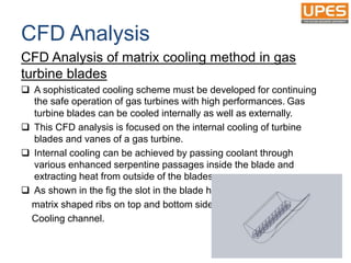
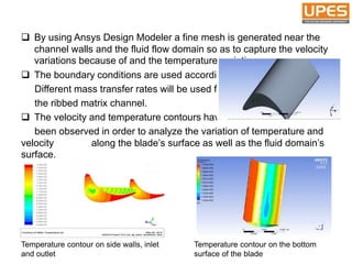
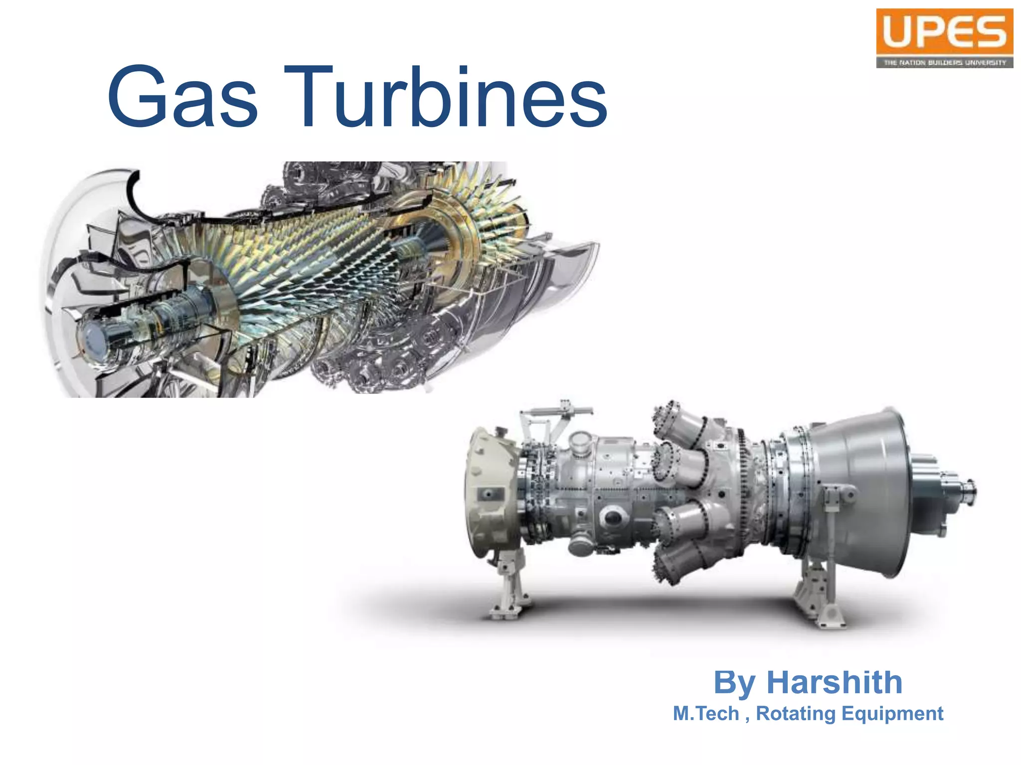
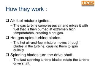
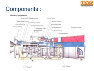
SlideShare a Scribd company logo
Gas Turbines
By Harshith
M.Tech , Rotating Equipment
What is Gas Turbine :
 They are one of the most widely-used
power generating technologies. Gas
turbines are a type of internal combustion
(IC) engine in which burning of an air-fuel
mixture produces hot gases that spin a
turbine to produce power.
How they work :
 Air-fuel mixture ignites.
– The gas turbine compresses air and mixes it with
fuel that is then burned at extremely high
temperatures, creating a hot gas.
 Hot gas spins turbine blades.
– The hot air-and-fuel mixture moves through
blades in the turbine, causing them to spin
quickly.
 Spinning blades turn the drive shaft.
– The fast-spinning turbine blades rotate the turbine
drive shaft.
 Turbine rotation powers the generator.
– The spinning turbine is connected to the rod in a
generator that turns a large magnet surrounded
by coils of copper wire.
 Generator magnet causes electrons to move
and creates electricity.
– The fast-revolving generator magnet creates a
powerful magnetic field that lines up the electrons
around the copper coils and causes them to
move.
– The movement of these electrons through a wire
is electricity.
Brayton Cycle
• Gas turbines are described thermodynamically by the
Brayton cycle.
• In this cycle:
1. Air is compressed isentropically
2. Combustion occurs at constant pressure
3. Heated air expands through the turbine
4. Heat is rejected into the atmosphere.
Components :
Fuel Technology in GT
 Understanding the need to ensure fuel quality is
maintained at a high standard is a key to delivering
good operation in a gas turbine over long periods of
time.
 The choice of fuels used in GT applications is very wide
with the choice Based on availability and cost. Gas
Turbines can and do operate on a wide range of fuels as
shown in the graph,
 Combustion technology has moved forwards in
achieving low emissions without resorting to wet
abatement methods. Both conventional and low
emissions technologies associated with the fuels are
developed.
 Graph shows various gaseous,
liquid, and solid fuels and the
wide range of lower heating
values (LHV).
 “Gaseous fuels” are shown as
green triangles or yellow,
orange and green ellipses.
 The blue ellipses and solid
blue dots indicate all of the
common and less-common “liquid fuels” , including bio fuels
and liquefied petroleum gas (LPG), butane, and propane, which
are between the gaseous and the liquid phase.
 “Solid fuels” including lignite and hard coal and are indicated
by black squares.
Fuels :
Fuel Injection Technology :
 The Fuel Injector is used to introduce fuel into
the combustion chamber.
There are four primary types of fuel injectors :
1. Pressure-atomizing
2. Air blast
3. Vaporizing
4. Premix/prevaporizing injectors
1. Pressure Atomizing
 Pressure atomizing fuel injectors rely on high fuel
pressures (500 psi) to atomize the fuel.
 This type of fuel injector has the advantage of being
very simple, but it has several disadvantages.
 The fuel system must be robust enough to
withstand such high pressures, and the
fuel tends to be heterogeneously
atomized, resulting in incomplete or
uneven combustion which has
more pollutants and smoke.
2. Air blast
 The Air blast injector "blasts" a sheet of fuel with a
stream of air, atomizing the fuel into homogeneous
droplets.
 This type of fuel injector led to the first smokeless
combustors.
 The air used is just same amount
of the primary air that is diverted
through the injector, rather than
the swirler. This type of injector
also requires lower fuel pressures
than the pressure atomizing type.
3. Vaporizing
 The vaporizing fuel injector is similar to the air blast
injector in which primary air is mixed with the fuel as it
is injected into the combustion zone.
 The fuel-air mixture travels through a tube within the
combustion zone. Heat from the combustion zone is
transferred to the fuel-air mixture, vaporizing some of
the fuel (mixing it better) before it is combusted. This
method allows the fuel to be combusted with
less thermal radiation, which helps protect the liner.
However, the vaporizer tube may have serious
durability problems with low fuel flow within it (the fuel
inside of the tube protects the tube from the combustion
heat).
4. Premix/pre-vaporizing
injectors
 The premixing/pre-vaporizing injectors work by
mixing or vaporizing the fuel before it reaches
the combustion zone.
 This method allows the fuel to be very uniformly
mixed with the air, reducing emissions from the
engine. One disadvantage of this method is that
fuel may auto-ignite or otherwise combust
before the fuel-air mixture reaches the
combustion zone. If this happens the combustor
can be seriously damaged.
Emissions :
 Different types of emissions are CO, NO and UHC.
1. CO [Carbon monoxide]
Causes:
 CO is produced in all fuel/air ratios.
 At low temperatures, that corresponding to low fuel/air ratios (Φpz < 0.5),
CO cannot be burnt to CO2.
 At high temperatures or high fuel/air ratios (Φpz > 0.9) on the other hand,
CO2 dissociates to CO.
Reduction:
 Improved fuel atomization.
 Holding the primary-zone equivalence ratio to its optimum value by
redistributing the air flow.
 Increase the residence time or the primary’s zone volume.
 Use of fuel staging.
 Use of compressed air-bleed.
2. UHC [Unburnt Hydrocarbons]
The parameters that influence CO emissions are also affecting
UHC emissions in the same way. So, UHC emissions reduction
requires the same treatment with CO emissions, but more attention
should be paid on the “reduction of film-cooling air” in the primary zone,
as well as on fuel atomization improvements. The latter could be
achieved with the use of airblast atomizers and air assist nozzles.
3. NO [Oxides of Nitrogen]
The principal parameter that governs NOx formation is temperature.
Reduction:
 Lean primary zone.
 Rich primary zone.
 Improved combustion’s homogeneity
 Use of water injection
 Recirculation of exhaust gas.
CFD Analysis
CFD Analysis of matrix cooling method in gas
turbine blades
 A sophisticated cooling scheme must be developed for continuing
the safe operation of gas turbines with high performances. Gas
turbine blades can be cooled internally as well as externally.
 This CFD analysis is focused on the internal cooling of turbine
blades and vanes of a gas turbine.
 Internal cooling can be achieved by passing coolant through
various enhanced serpentine passages inside the blade and
extracting heat from outside of the blades.
 As shown in the fig the slot in the blade has
matrix shaped ribs on top and bottom side of
Cooling channel.
 By using Ansys Design Modeler a fine mesh is generated near the
channel walls and the fluid flow domain so as to capture the velocity
variations because of and the temperature variations.
 The boundary conditions are used accordingly.
Different mass transfer rates will be used for
the ribbed matrix channel.
 The velocity and temperature contours have
been observed in order to analyze the variation of temperature and
velocity . along the blade’s surface as well as the fluid domain’s
surface.
Temperature contour on side walls, inlet
and outlet
Temperature contour on the bottom
surface of the blade
Gas Turbine Manufacturers :
Thank You

More Related Content

What's hot

Steam power plant
Steam power plantSteam power plant
Steam power plant
Nishkam Dhiman
 
Air Injection and Solid Injection System
Air Injection and Solid Injection SystemAir Injection and Solid Injection System
Air Injection and Solid Injection System
Parthivpal17
 
Steam Turbines Basics
Steam Turbines BasicsSteam Turbines Basics
Steam Turbines Basics
Prasad Vejendla
 
THERMAL POWER ENGINEERING
THERMAL POWER ENGINEERINGTHERMAL POWER ENGINEERING
THERMAL POWER ENGINEERING
Sajal Tiwari
 
Knocking &amp; detonation
Knocking &amp; detonationKnocking &amp; detonation
Knocking &amp; detonation
Qabool Ahmed Memon
 
COMBUSTION IN S I & C I ENGINES
COMBUSTION IN S I & C I ENGINESCOMBUSTION IN S I & C I ENGINES
COMBUSTION IN S I & C I ENGINES
Jim Alex
 
Gas Turbine Basics.pdf
Gas Turbine Basics.pdfGas Turbine Basics.pdf
Gas Turbine Basics.pdf
yusuf699644
 
Final Turbine rolling ppt Akshay.pptx
Final Turbine rolling ppt Akshay.pptxFinal Turbine rolling ppt Akshay.pptx
Final Turbine rolling ppt Akshay.pptx
BhimarajuKanireddy
 
Steam turbine introduction & maintenance ppt
Steam turbine introduction & maintenance pptSteam turbine introduction & maintenance ppt
Steam turbine introduction & maintenance ppt
Biswajit Mohanty
 
Heat recovery steam generator (HRSG) condition monitoring methods
Heat recovery steam generator (HRSG) condition monitoring methodsHeat recovery steam generator (HRSG) condition monitoring methods
Heat recovery steam generator (HRSG) condition monitoring methods
mahdi esfahani
 
Calculation of Turbine Efficiency
Calculation of Turbine EfficiencyCalculation of Turbine Efficiency
Calculation of Turbine Efficiency
Jahanzeb Khan
 
Gas power plant
Gas power plantGas power plant
Gas power plant
Amit Sinha
 
MET 401 Chapter 3 fuels_and_combustion
MET 401 Chapter 3 fuels_and_combustionMET 401 Chapter 3 fuels_and_combustion
MET 401 Chapter 3 fuels_and_combustion
Ibrahim AboKhalil
 
Air standard cycle
Air standard cycleAir standard cycle
Air standard cycle
Dodiya Nikunj
 
Turbo expander compressor
Turbo expander compressorTurbo expander compressor
Turbo expander compressor
Mahendra Prabhu S
 
Boiler Efficiency Calculations
Boiler Efficiency CalculationsBoiler Efficiency Calculations
Boiler Efficiency Calculations
Manohar Tatwawadi
 
287649737 90325-presentation-hrsg
287649737 90325-presentation-hrsg287649737 90325-presentation-hrsg
287649737 90325-presentation-hrsg
Srikanth321
 
Diesel power plant
Diesel power plantDiesel power plant
Diesel power plant
Nishkam Dhiman
 
CI engine
CI engineCI engine
CI engine
sachin chaurasia
 
Gas turbine
Gas turbine Gas turbine
Gas turbine
Manu Khurana
 

What's hot (20)

Steam power plant
Steam power plantSteam power plant
Steam power plant
 
Air Injection and Solid Injection System
Air Injection and Solid Injection SystemAir Injection and Solid Injection System
Air Injection and Solid Injection System
 
Steam Turbines Basics
Steam Turbines BasicsSteam Turbines Basics
Steam Turbines Basics
 
THERMAL POWER ENGINEERING
THERMAL POWER ENGINEERINGTHERMAL POWER ENGINEERING
THERMAL POWER ENGINEERING
 
Knocking &amp; detonation
Knocking &amp; detonationKnocking &amp; detonation
Knocking &amp; detonation
 
COMBUSTION IN S I & C I ENGINES
COMBUSTION IN S I & C I ENGINESCOMBUSTION IN S I & C I ENGINES
COMBUSTION IN S I & C I ENGINES
 
Gas Turbine Basics.pdf
Gas Turbine Basics.pdfGas Turbine Basics.pdf
Gas Turbine Basics.pdf
 
Final Turbine rolling ppt Akshay.pptx
Final Turbine rolling ppt Akshay.pptxFinal Turbine rolling ppt Akshay.pptx
Final Turbine rolling ppt Akshay.pptx
 
Steam turbine introduction & maintenance ppt
Steam turbine introduction & maintenance pptSteam turbine introduction & maintenance ppt
Steam turbine introduction & maintenance ppt
 
Heat recovery steam generator (HRSG) condition monitoring methods
Heat recovery steam generator (HRSG) condition monitoring methodsHeat recovery steam generator (HRSG) condition monitoring methods
Heat recovery steam generator (HRSG) condition monitoring methods
 
Calculation of Turbine Efficiency
Calculation of Turbine EfficiencyCalculation of Turbine Efficiency
Calculation of Turbine Efficiency
 
Gas power plant
Gas power plantGas power plant
Gas power plant
 
MET 401 Chapter 3 fuels_and_combustion
MET 401 Chapter 3 fuels_and_combustionMET 401 Chapter 3 fuels_and_combustion
MET 401 Chapter 3 fuels_and_combustion
 
Air standard cycle
Air standard cycleAir standard cycle
Air standard cycle
 
Turbo expander compressor
Turbo expander compressorTurbo expander compressor
Turbo expander compressor
 
Boiler Efficiency Calculations
Boiler Efficiency CalculationsBoiler Efficiency Calculations
Boiler Efficiency Calculations
 
287649737 90325-presentation-hrsg
287649737 90325-presentation-hrsg287649737 90325-presentation-hrsg
287649737 90325-presentation-hrsg
 
Diesel power plant
Diesel power plantDiesel power plant
Diesel power plant
 
CI engine
CI engineCI engine
CI engine
 
Gas turbine
Gas turbine Gas turbine
Gas turbine
 

Similar to Gas turbines

Combustion chamber of Gas turbine power plant cycle
Combustion chamber of Gas turbine power plant cycleCombustion chamber of Gas turbine power plant cycle
Combustion chamber of Gas turbine power plant cycle
manjeet singh minhas
 
Brayton cycle for gas turbine
Brayton cycle for gas turbineBrayton cycle for gas turbine
Brayton cycle for gas turbine
Nikhil Nagdev
 
AICE- UNIT-3.pptx
AICE- UNIT-3.pptxAICE- UNIT-3.pptx
AICE- UNIT-3.pptx
GunaSekaran958261
 
advanced engine automobile EMISSION CONTROL
advanced engine automobile EMISSION  CONTROLadvanced engine automobile EMISSION  CONTROL
advanced engine automobile EMISSION CONTROL
samy709581
 
UNIT-3 EMISSION FORMATION AND CONTROL.pptx
UNIT-3 EMISSION FORMATION AND CONTROL.pptxUNIT-3 EMISSION FORMATION AND CONTROL.pptx
UNIT-3 EMISSION FORMATION AND CONTROL.pptx
Dr.G.Saravanan
 
ADVANCED IC ENGINES-UNIT-3.pptx
ADVANCED IC ENGINES-UNIT-3.pptxADVANCED IC ENGINES-UNIT-3.pptx
ADVANCED IC ENGINES-UNIT-3.pptx
Maniyarasan M
 
Flame Stability
Flame StabilityFlame Stability
Flame Stability
Rahat Inayat Ali
 
Gas Turbine and Jet propulsion
Gas Turbine and Jet propulsionGas Turbine and Jet propulsion
Gas Turbine and Jet propulsion
SLA1987
 
FIRED HEATERS .ppt
FIRED HEATERS .pptFIRED HEATERS .ppt
FIRED HEATERS .ppt
ABDURREHMANKHALID5
 
Ppe (2)
Ppe (2)Ppe (2)
Combustion equipments for fuels (1)
Combustion equipments for fuels (1)Combustion equipments for fuels (1)
Combustion equipments for fuels (1)
Shri Mata Vaishno Devi University
 
Combustion equipments for fuels
Combustion equipments for fuelsCombustion equipments for fuels
Combustion equipments for fuels
Anam Wani
 
Gas turbine plant
Gas turbine plantGas turbine plant
Gas turbine plant
rajendrasm
 
Comparison of cycles and measurement of exhaust gases.pptx
Comparison of cycles and measurement of exhaust gases.pptxComparison of cycles and measurement of exhaust gases.pptx
Comparison of cycles and measurement of exhaust gases.pptx
SAshwinDaniel
 
Turbojet- Sumit Prajapati (07ME105)
Turbojet- Sumit Prajapati (07ME105)Turbojet- Sumit Prajapati (07ME105)
Turbojet- Sumit Prajapati (07ME105)
Sumit Prajapati
 
Turbojet engines
Turbojet enginesTurbojet engines
Turbojet engines
pranav teli
 
Turbojets
TurbojetsTurbojets
Turbojets
ahsen nasim
 
Turbojet engines
Turbojet enginesTurbojet engines
Turbojet engines
STAY CURIOUS
 
UNIT 2 PPE.ppt
UNIT 2 PPE.pptUNIT 2 PPE.ppt
UNIT 2 PPE.ppt
Rajeswarijana
 
H012445056
H012445056H012445056
H012445056
IOSR Journals
 

Similar to Gas turbines (20)

Combustion chamber of Gas turbine power plant cycle
Combustion chamber of Gas turbine power plant cycleCombustion chamber of Gas turbine power plant cycle
Combustion chamber of Gas turbine power plant cycle
 
Brayton cycle for gas turbine
Brayton cycle for gas turbineBrayton cycle for gas turbine
Brayton cycle for gas turbine
 
AICE- UNIT-3.pptx
AICE- UNIT-3.pptxAICE- UNIT-3.pptx
AICE- UNIT-3.pptx
 
advanced engine automobile EMISSION CONTROL
advanced engine automobile EMISSION  CONTROLadvanced engine automobile EMISSION  CONTROL
advanced engine automobile EMISSION CONTROL
 
UNIT-3 EMISSION FORMATION AND CONTROL.pptx
UNIT-3 EMISSION FORMATION AND CONTROL.pptxUNIT-3 EMISSION FORMATION AND CONTROL.pptx
UNIT-3 EMISSION FORMATION AND CONTROL.pptx
 
ADVANCED IC ENGINES-UNIT-3.pptx
ADVANCED IC ENGINES-UNIT-3.pptxADVANCED IC ENGINES-UNIT-3.pptx
ADVANCED IC ENGINES-UNIT-3.pptx
 
Flame Stability
Flame StabilityFlame Stability
Flame Stability
 
Gas Turbine and Jet propulsion
Gas Turbine and Jet propulsionGas Turbine and Jet propulsion
Gas Turbine and Jet propulsion
 
FIRED HEATERS .ppt
FIRED HEATERS .pptFIRED HEATERS .ppt
FIRED HEATERS .ppt
 
Ppe (2)
Ppe (2)Ppe (2)
Ppe (2)
 
Combustion equipments for fuels (1)
Combustion equipments for fuels (1)Combustion equipments for fuels (1)
Combustion equipments for fuels (1)
 
Combustion equipments for fuels
Combustion equipments for fuelsCombustion equipments for fuels
Combustion equipments for fuels
 
Gas turbine plant
Gas turbine plantGas turbine plant
Gas turbine plant
 
Comparison of cycles and measurement of exhaust gases.pptx
Comparison of cycles and measurement of exhaust gases.pptxComparison of cycles and measurement of exhaust gases.pptx
Comparison of cycles and measurement of exhaust gases.pptx
 
Turbojet- Sumit Prajapati (07ME105)
Turbojet- Sumit Prajapati (07ME105)Turbojet- Sumit Prajapati (07ME105)
Turbojet- Sumit Prajapati (07ME105)
 
Turbojet engines
Turbojet enginesTurbojet engines
Turbojet engines
 
Turbojets
TurbojetsTurbojets
Turbojets
 
Turbojet engines
Turbojet enginesTurbojet engines
Turbojet engines
 
UNIT 2 PPE.ppt
UNIT 2 PPE.pptUNIT 2 PPE.ppt
UNIT 2 PPE.ppt
 
H012445056
H012445056H012445056
H012445056
 

Recently uploaded

1FIDIC-CONSTRUCTION-CONTRACT-2ND-ED-2017-RED-BOOK.pdf
1FIDIC-CONSTRUCTION-CONTRACT-2ND-ED-2017-RED-BOOK.pdf1FIDIC-CONSTRUCTION-CONTRACT-2ND-ED-2017-RED-BOOK.pdf
1FIDIC-CONSTRUCTION-CONTRACT-2ND-ED-2017-RED-BOOK.pdf
MadhavJungKarki
 
Mechanical Engineering on AAI Summer Training Report-003.pdf
Mechanical Engineering on AAI Summer Training Report-003.pdfMechanical Engineering on AAI Summer Training Report-003.pdf
Mechanical Engineering on AAI Summer Training Report-003.pdf
21UME003TUSHARDEB
 
AI-Based Home Security System : Home security
AI-Based Home Security System : Home securityAI-Based Home Security System : Home security
AI-Based Home Security System : Home security
AIRCC Publishing Corporation
 
Zener Diode and its V-I Characteristics and Applications
Zener Diode and its V-I Characteristics and ApplicationsZener Diode and its V-I Characteristics and Applications
Zener Diode and its V-I Characteristics and Applications
Shiny Christobel
 
DEEP LEARNING FOR SMART GRID INTRUSION DETECTION: A HYBRID CNN-LSTM-BASED MODEL
DEEP LEARNING FOR SMART GRID INTRUSION DETECTION: A HYBRID CNN-LSTM-BASED MODELDEEP LEARNING FOR SMART GRID INTRUSION DETECTION: A HYBRID CNN-LSTM-BASED MODEL
DEEP LEARNING FOR SMART GRID INTRUSION DETECTION: A HYBRID CNN-LSTM-BASED MODEL
ijaia
 
Null Bangalore | Pentesters Approach to AWS IAM
Null Bangalore | Pentesters Approach to AWS IAMNull Bangalore | Pentesters Approach to AWS IAM
Null Bangalore | Pentesters Approach to AWS IAM
Divyanshu
 
Supermarket Management System Project Report.pdf
Supermarket Management System Project Report.pdfSupermarket Management System Project Report.pdf
Supermarket Management System Project Report.pdf
Kamal Acharya
 
Height and depth gauge linear metrology.pdf
Height and depth gauge linear metrology.pdfHeight and depth gauge linear metrology.pdf
Height and depth gauge linear metrology.pdf
q30122000
 
Software Engineering and Project Management - Introduction, Modeling Concepts...
Software Engineering and Project Management - Introduction, Modeling Concepts...Software Engineering and Project Management - Introduction, Modeling Concepts...
Software Engineering and Project Management - Introduction, Modeling Concepts...
Prakhyath Rai
 
ITSM Integration with MuleSoft.pptx
ITSM  Integration with MuleSoft.pptxITSM  Integration with MuleSoft.pptx
ITSM Integration with MuleSoft.pptx
VANDANAMOHANGOUDA
 
一比一原版(USF毕业证)旧金山大学毕业证如何办理
一比一原版(USF毕业证)旧金山大学毕业证如何办理一比一原版(USF毕业证)旧金山大学毕业证如何办理
一比一原版(USF毕业证)旧金山大学毕业证如何办理
uqyfuc
 
Blood finder application project report (1).pdf
Blood finder application project report (1).pdfBlood finder application project report (1).pdf
Blood finder application project report (1).pdf
Kamal Acharya
 
一比一原版(osu毕业证书)美国俄勒冈州立大学毕业证如何办理
一比一原版(osu毕业证书)美国俄勒冈州立大学毕业证如何办理一比一原版(osu毕业证书)美国俄勒冈州立大学毕业证如何办理
一比一原版(osu毕业证书)美国俄勒冈州立大学毕业证如何办理
upoux
 
原版制作(Humboldt毕业证书)柏林大学毕业证学位证一模一样
原版制作(Humboldt毕业证书)柏林大学毕业证学位证一模一样原版制作(Humboldt毕业证书)柏林大学毕业证学位证一模一样
原版制作(Humboldt毕业证书)柏林大学毕业证学位证一模一样
ydzowc
 
SCALING OF MOS CIRCUITS m .pptx
SCALING OF MOS CIRCUITS m                 .pptxSCALING OF MOS CIRCUITS m                 .pptx
SCALING OF MOS CIRCUITS m .pptx
harshapolam10
 
Object Oriented Analysis and Design - OOAD
Object Oriented Analysis and Design - OOADObject Oriented Analysis and Design - OOAD
Object Oriented Analysis and Design - OOAD
PreethaV16
 
Data Driven Maintenance | UReason Webinar
Data Driven Maintenance | UReason WebinarData Driven Maintenance | UReason Webinar
Data Driven Maintenance | UReason Webinar
UReason
 
一比一原版(CalArts毕业证)加利福尼亚艺术学院毕业证如何办理
一比一原版(CalArts毕业证)加利福尼亚艺术学院毕业证如何办理一比一原版(CalArts毕业证)加利福尼亚艺术学院毕业证如何办理
一比一原版(CalArts毕业证)加利福尼亚艺术学院毕业证如何办理
ecqow
 
LLM Fine Tuning with QLoRA Cassandra Lunch 4, presented by Anant
LLM Fine Tuning with QLoRA Cassandra Lunch 4, presented by AnantLLM Fine Tuning with QLoRA Cassandra Lunch 4, presented by Anant
LLM Fine Tuning with QLoRA Cassandra Lunch 4, presented by Anant
Anant Corporation
 
Pressure Relief valve used in flow line to release the over pressure at our d...
Pressure Relief valve used in flow line to release the over pressure at our d...Pressure Relief valve used in flow line to release the over pressure at our d...
Pressure Relief valve used in flow line to release the over pressure at our d...
cannyengineerings
 

Recently uploaded (20)

1FIDIC-CONSTRUCTION-CONTRACT-2ND-ED-2017-RED-BOOK.pdf
1FIDIC-CONSTRUCTION-CONTRACT-2ND-ED-2017-RED-BOOK.pdf1FIDIC-CONSTRUCTION-CONTRACT-2ND-ED-2017-RED-BOOK.pdf
1FIDIC-CONSTRUCTION-CONTRACT-2ND-ED-2017-RED-BOOK.pdf
 
Mechanical Engineering on AAI Summer Training Report-003.pdf
Mechanical Engineering on AAI Summer Training Report-003.pdfMechanical Engineering on AAI Summer Training Report-003.pdf
Mechanical Engineering on AAI Summer Training Report-003.pdf
 
AI-Based Home Security System : Home security
AI-Based Home Security System : Home securityAI-Based Home Security System : Home security
AI-Based Home Security System : Home security
 
Zener Diode and its V-I Characteristics and Applications
Zener Diode and its V-I Characteristics and ApplicationsZener Diode and its V-I Characteristics and Applications
Zener Diode and its V-I Characteristics and Applications
 
DEEP LEARNING FOR SMART GRID INTRUSION DETECTION: A HYBRID CNN-LSTM-BASED MODEL
DEEP LEARNING FOR SMART GRID INTRUSION DETECTION: A HYBRID CNN-LSTM-BASED MODELDEEP LEARNING FOR SMART GRID INTRUSION DETECTION: A HYBRID CNN-LSTM-BASED MODEL
DEEP LEARNING FOR SMART GRID INTRUSION DETECTION: A HYBRID CNN-LSTM-BASED MODEL
 
Null Bangalore | Pentesters Approach to AWS IAM
Null Bangalore | Pentesters Approach to AWS IAMNull Bangalore | Pentesters Approach to AWS IAM
Null Bangalore | Pentesters Approach to AWS IAM
 
Supermarket Management System Project Report.pdf
Supermarket Management System Project Report.pdfSupermarket Management System Project Report.pdf
Supermarket Management System Project Report.pdf
 
Height and depth gauge linear metrology.pdf
Height and depth gauge linear metrology.pdfHeight and depth gauge linear metrology.pdf
Height and depth gauge linear metrology.pdf
 
Software Engineering and Project Management - Introduction, Modeling Concepts...
Software Engineering and Project Management - Introduction, Modeling Concepts...Software Engineering and Project Management - Introduction, Modeling Concepts...
Software Engineering and Project Management - Introduction, Modeling Concepts...
 
ITSM Integration with MuleSoft.pptx
ITSM  Integration with MuleSoft.pptxITSM  Integration with MuleSoft.pptx
ITSM Integration with MuleSoft.pptx
 
一比一原版(USF毕业证)旧金山大学毕业证如何办理
一比一原版(USF毕业证)旧金山大学毕业证如何办理一比一原版(USF毕业证)旧金山大学毕业证如何办理
一比一原版(USF毕业证)旧金山大学毕业证如何办理
 
Blood finder application project report (1).pdf
Blood finder application project report (1).pdfBlood finder application project report (1).pdf
Blood finder application project report (1).pdf
 
一比一原版(osu毕业证书)美国俄勒冈州立大学毕业证如何办理
一比一原版(osu毕业证书)美国俄勒冈州立大学毕业证如何办理一比一原版(osu毕业证书)美国俄勒冈州立大学毕业证如何办理
一比一原版(osu毕业证书)美国俄勒冈州立大学毕业证如何办理
 
原版制作(Humboldt毕业证书)柏林大学毕业证学位证一模一样
原版制作(Humboldt毕业证书)柏林大学毕业证学位证一模一样原版制作(Humboldt毕业证书)柏林大学毕业证学位证一模一样
原版制作(Humboldt毕业证书)柏林大学毕业证学位证一模一样
 
SCALING OF MOS CIRCUITS m .pptx
SCALING OF MOS CIRCUITS m                 .pptxSCALING OF MOS CIRCUITS m                 .pptx
SCALING OF MOS CIRCUITS m .pptx
 
Object Oriented Analysis and Design - OOAD
Object Oriented Analysis and Design - OOADObject Oriented Analysis and Design - OOAD
Object Oriented Analysis and Design - OOAD
 
Data Driven Maintenance | UReason Webinar
Data Driven Maintenance | UReason WebinarData Driven Maintenance | UReason Webinar
Data Driven Maintenance | UReason Webinar
 
一比一原版(CalArts毕业证)加利福尼亚艺术学院毕业证如何办理
一比一原版(CalArts毕业证)加利福尼亚艺术学院毕业证如何办理一比一原版(CalArts毕业证)加利福尼亚艺术学院毕业证如何办理
一比一原版(CalArts毕业证)加利福尼亚艺术学院毕业证如何办理
 
LLM Fine Tuning with QLoRA Cassandra Lunch 4, presented by Anant
LLM Fine Tuning with QLoRA Cassandra Lunch 4, presented by AnantLLM Fine Tuning with QLoRA Cassandra Lunch 4, presented by Anant
LLM Fine Tuning with QLoRA Cassandra Lunch 4, presented by Anant
 
Pressure Relief valve used in flow line to release the over pressure at our d...
Pressure Relief valve used in flow line to release the over pressure at our d...Pressure Relief valve used in flow line to release the over pressure at our d...
Pressure Relief valve used in flow line to release the over pressure at our d...
 

Gas turbines

  • 1. Gas Turbines By Harshith M.Tech , Rotating Equipment
  • 2. What is Gas Turbine :  They are one of the most widely-used power generating technologies. Gas turbines are a type of internal combustion (IC) engine in which burning of an air-fuel mixture produces hot gases that spin a turbine to produce power.
  • 3. How they work :  Air-fuel mixture ignites. – The gas turbine compresses air and mixes it with fuel that is then burned at extremely high temperatures, creating a hot gas.  Hot gas spins turbine blades. – The hot air-and-fuel mixture moves through blades in the turbine, causing them to spin quickly.  Spinning blades turn the drive shaft. – The fast-spinning turbine blades rotate the turbine drive shaft.
  • 4.  Turbine rotation powers the generator. – The spinning turbine is connected to the rod in a generator that turns a large magnet surrounded by coils of copper wire.  Generator magnet causes electrons to move and creates electricity. – The fast-revolving generator magnet creates a powerful magnetic field that lines up the electrons around the copper coils and causes them to move. – The movement of these electrons through a wire is electricity.
  • 5. Brayton Cycle • Gas turbines are described thermodynamically by the Brayton cycle. • In this cycle: 1. Air is compressed isentropically 2. Combustion occurs at constant pressure 3. Heated air expands through the turbine 4. Heat is rejected into the atmosphere.
  • 7. Fuel Technology in GT  Understanding the need to ensure fuel quality is maintained at a high standard is a key to delivering good operation in a gas turbine over long periods of time.  The choice of fuels used in GT applications is very wide with the choice Based on availability and cost. Gas Turbines can and do operate on a wide range of fuels as shown in the graph,  Combustion technology has moved forwards in achieving low emissions without resorting to wet abatement methods. Both conventional and low emissions technologies associated with the fuels are developed.
  • 8.  Graph shows various gaseous, liquid, and solid fuels and the wide range of lower heating values (LHV).  “Gaseous fuels” are shown as green triangles or yellow, orange and green ellipses.  The blue ellipses and solid blue dots indicate all of the common and less-common “liquid fuels” , including bio fuels and liquefied petroleum gas (LPG), butane, and propane, which are between the gaseous and the liquid phase.  “Solid fuels” including lignite and hard coal and are indicated by black squares. Fuels :
  • 9. Fuel Injection Technology :  The Fuel Injector is used to introduce fuel into the combustion chamber. There are four primary types of fuel injectors : 1. Pressure-atomizing 2. Air blast 3. Vaporizing 4. Premix/prevaporizing injectors
  • 10. 1. Pressure Atomizing  Pressure atomizing fuel injectors rely on high fuel pressures (500 psi) to atomize the fuel.  This type of fuel injector has the advantage of being very simple, but it has several disadvantages.  The fuel system must be robust enough to withstand such high pressures, and the fuel tends to be heterogeneously atomized, resulting in incomplete or uneven combustion which has more pollutants and smoke.
  • 11. 2. Air blast  The Air blast injector "blasts" a sheet of fuel with a stream of air, atomizing the fuel into homogeneous droplets.  This type of fuel injector led to the first smokeless combustors.  The air used is just same amount of the primary air that is diverted through the injector, rather than the swirler. This type of injector also requires lower fuel pressures than the pressure atomizing type.
  • 12. 3. Vaporizing  The vaporizing fuel injector is similar to the air blast injector in which primary air is mixed with the fuel as it is injected into the combustion zone.  The fuel-air mixture travels through a tube within the combustion zone. Heat from the combustion zone is transferred to the fuel-air mixture, vaporizing some of the fuel (mixing it better) before it is combusted. This method allows the fuel to be combusted with less thermal radiation, which helps protect the liner. However, the vaporizer tube may have serious durability problems with low fuel flow within it (the fuel inside of the tube protects the tube from the combustion heat).
  • 13. 4. Premix/pre-vaporizing injectors  The premixing/pre-vaporizing injectors work by mixing or vaporizing the fuel before it reaches the combustion zone.  This method allows the fuel to be very uniformly mixed with the air, reducing emissions from the engine. One disadvantage of this method is that fuel may auto-ignite or otherwise combust before the fuel-air mixture reaches the combustion zone. If this happens the combustor can be seriously damaged.
  • 14. Emissions :  Different types of emissions are CO, NO and UHC. 1. CO [Carbon monoxide] Causes:  CO is produced in all fuel/air ratios.  At low temperatures, that corresponding to low fuel/air ratios (Φpz < 0.5), CO cannot be burnt to CO2.  At high temperatures or high fuel/air ratios (Φpz > 0.9) on the other hand, CO2 dissociates to CO. Reduction:  Improved fuel atomization.  Holding the primary-zone equivalence ratio to its optimum value by redistributing the air flow.  Increase the residence time or the primary’s zone volume.  Use of fuel staging.  Use of compressed air-bleed.
  • 15. 2. UHC [Unburnt Hydrocarbons] The parameters that influence CO emissions are also affecting UHC emissions in the same way. So, UHC emissions reduction requires the same treatment with CO emissions, but more attention should be paid on the “reduction of film-cooling air” in the primary zone, as well as on fuel atomization improvements. The latter could be achieved with the use of airblast atomizers and air assist nozzles. 3. NO [Oxides of Nitrogen] The principal parameter that governs NOx formation is temperature. Reduction:  Lean primary zone.  Rich primary zone.  Improved combustion’s homogeneity  Use of water injection  Recirculation of exhaust gas.
  • 16. CFD Analysis CFD Analysis of matrix cooling method in gas turbine blades  A sophisticated cooling scheme must be developed for continuing the safe operation of gas turbines with high performances. Gas turbine blades can be cooled internally as well as externally.  This CFD analysis is focused on the internal cooling of turbine blades and vanes of a gas turbine.  Internal cooling can be achieved by passing coolant through various enhanced serpentine passages inside the blade and extracting heat from outside of the blades.  As shown in the fig the slot in the blade has matrix shaped ribs on top and bottom side of Cooling channel.
  • 17.  By using Ansys Design Modeler a fine mesh is generated near the channel walls and the fluid flow domain so as to capture the velocity variations because of and the temperature variations.  The boundary conditions are used accordingly. Different mass transfer rates will be used for the ribbed matrix channel.  The velocity and temperature contours have been observed in order to analyze the variation of temperature and velocity . along the blade’s surface as well as the fluid domain’s surface. Temperature contour on side walls, inlet and outlet Temperature contour on the bottom surface of the blade
  • 19.