Downloaded 1,130 times

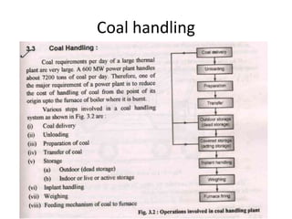
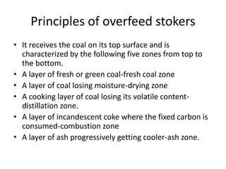
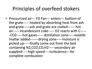
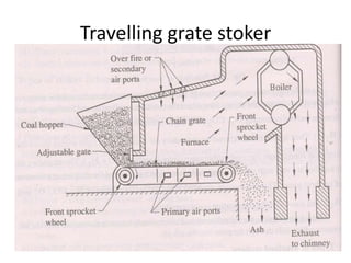
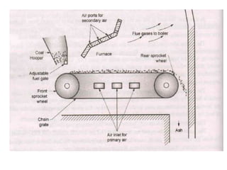
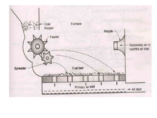
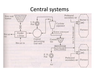
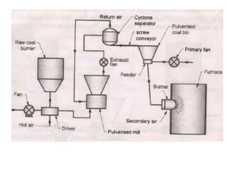
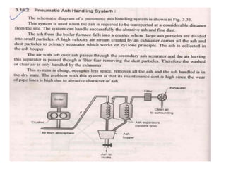
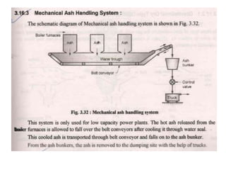
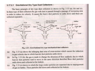

This document discusses coal handling and storage methods at power plants. It describes dead storage or outdoor storage where coal is piled directly on the ground, which can lead to spontaneous combustion from oxidation. It then discusses live storage in vertical bunkers or silos. The document also covers different types of stoker firing systems used to burn coal, including travelling grate stokers and spreader stokers. Finally, it summarizes pulverized coal firing and the unit and central systems used to grind, dry and feed pulverized coal to boiler furnaces.


