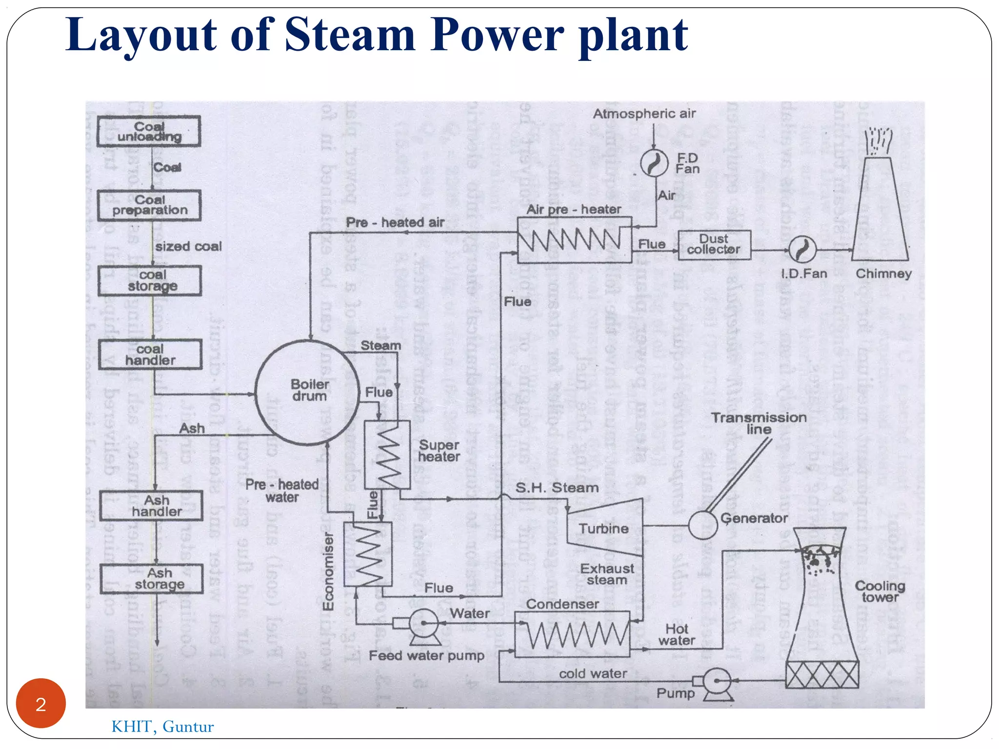
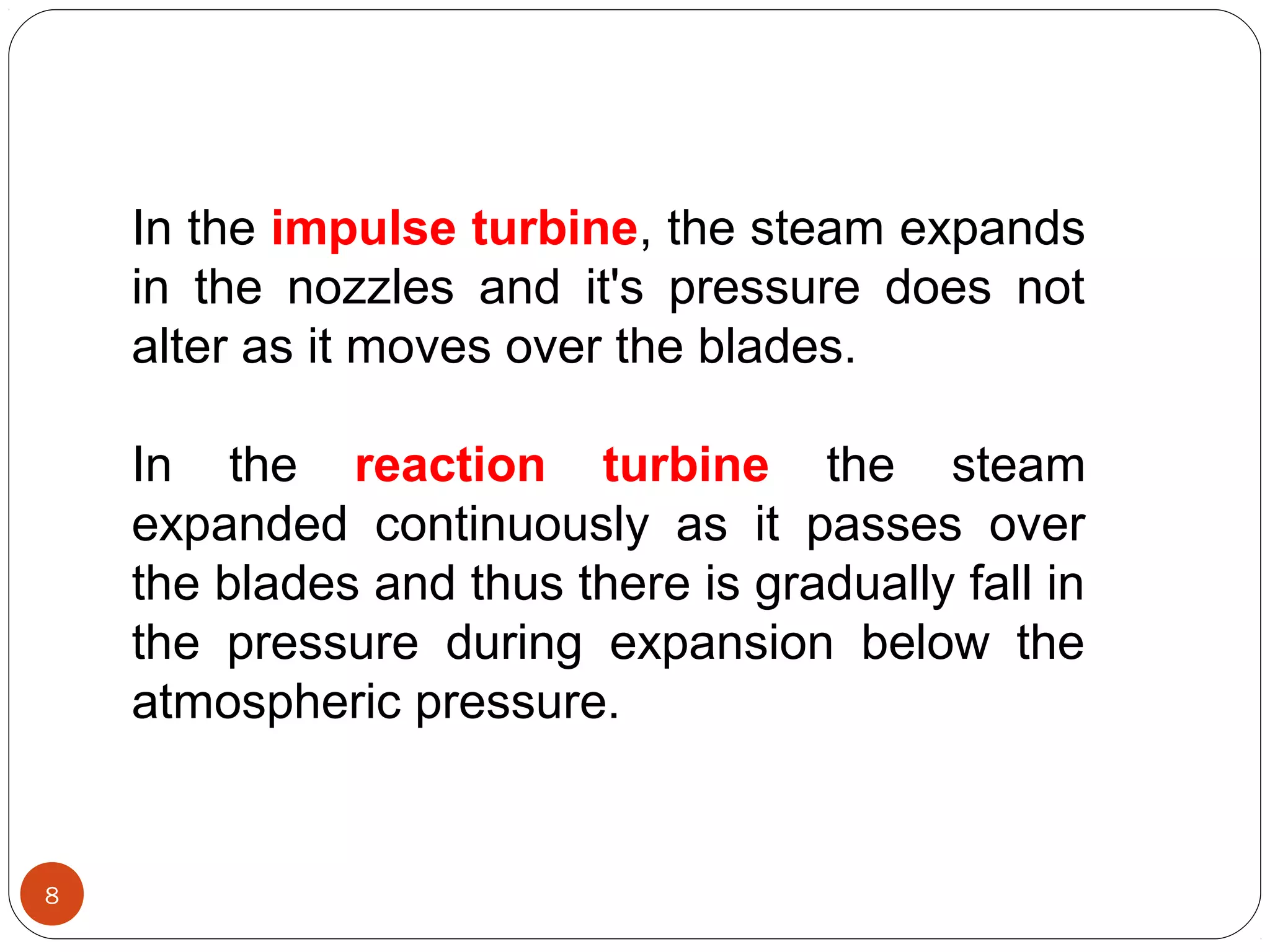
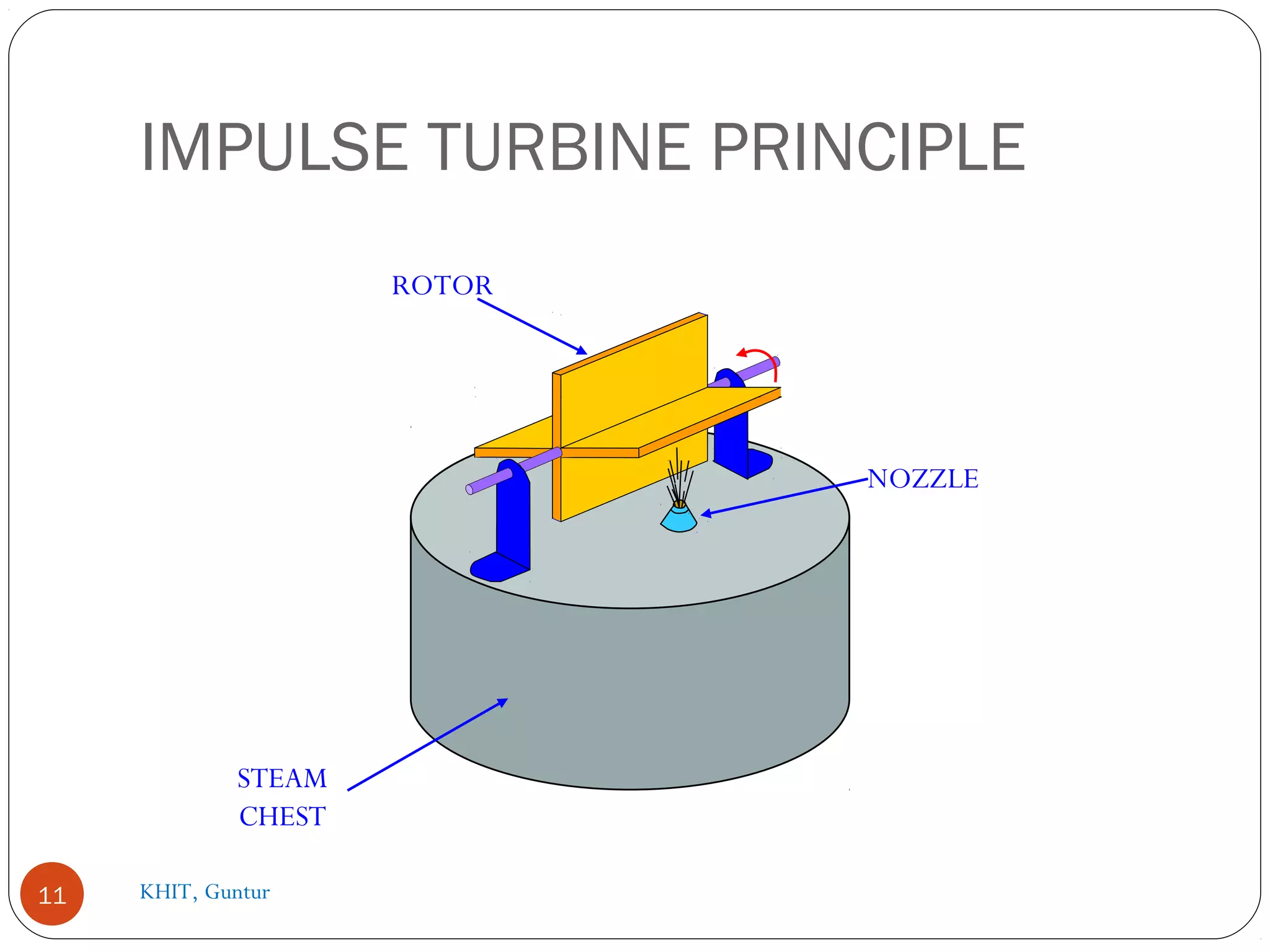
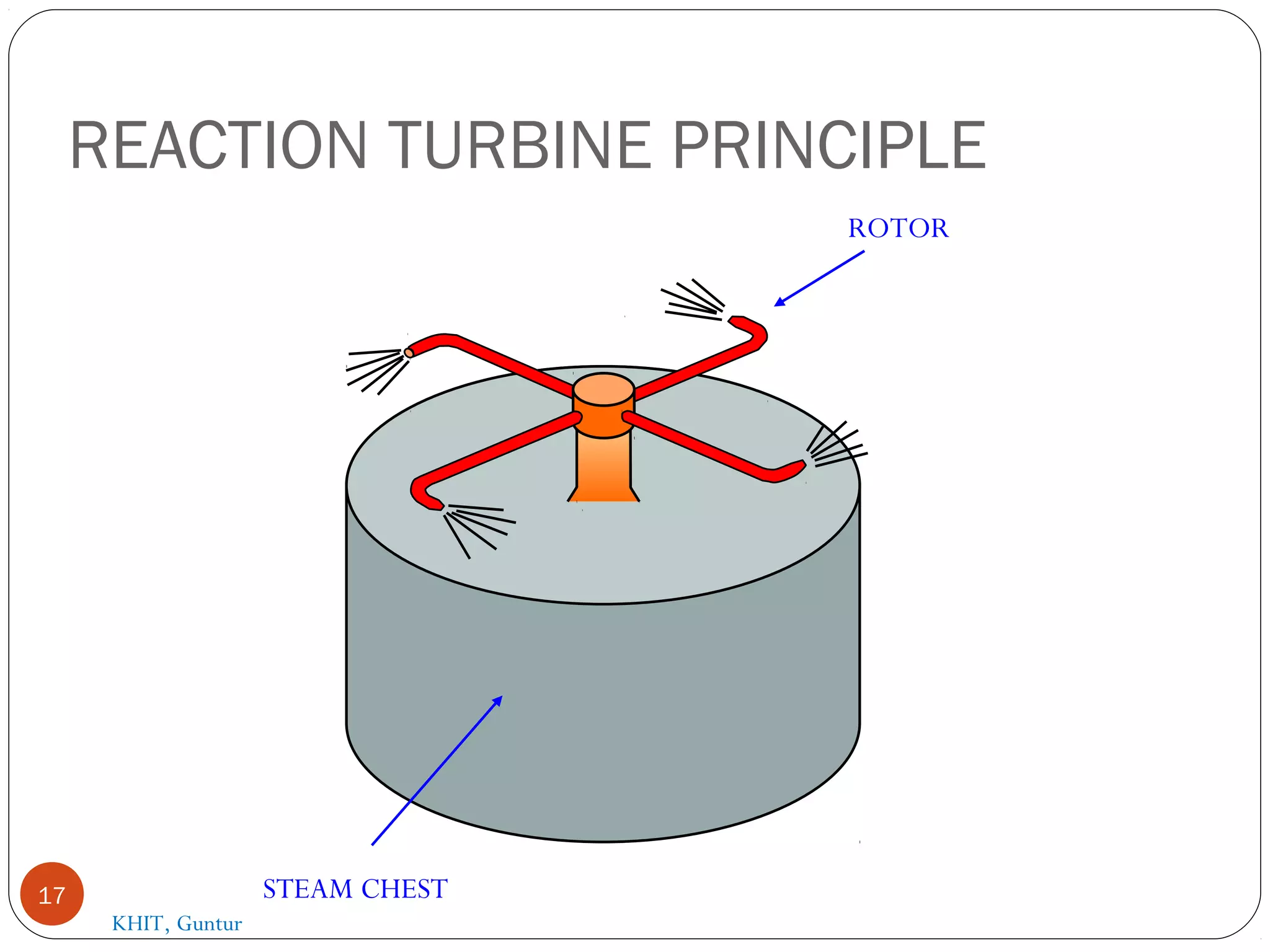
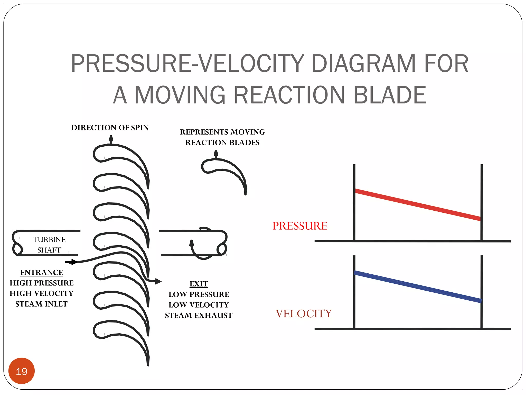
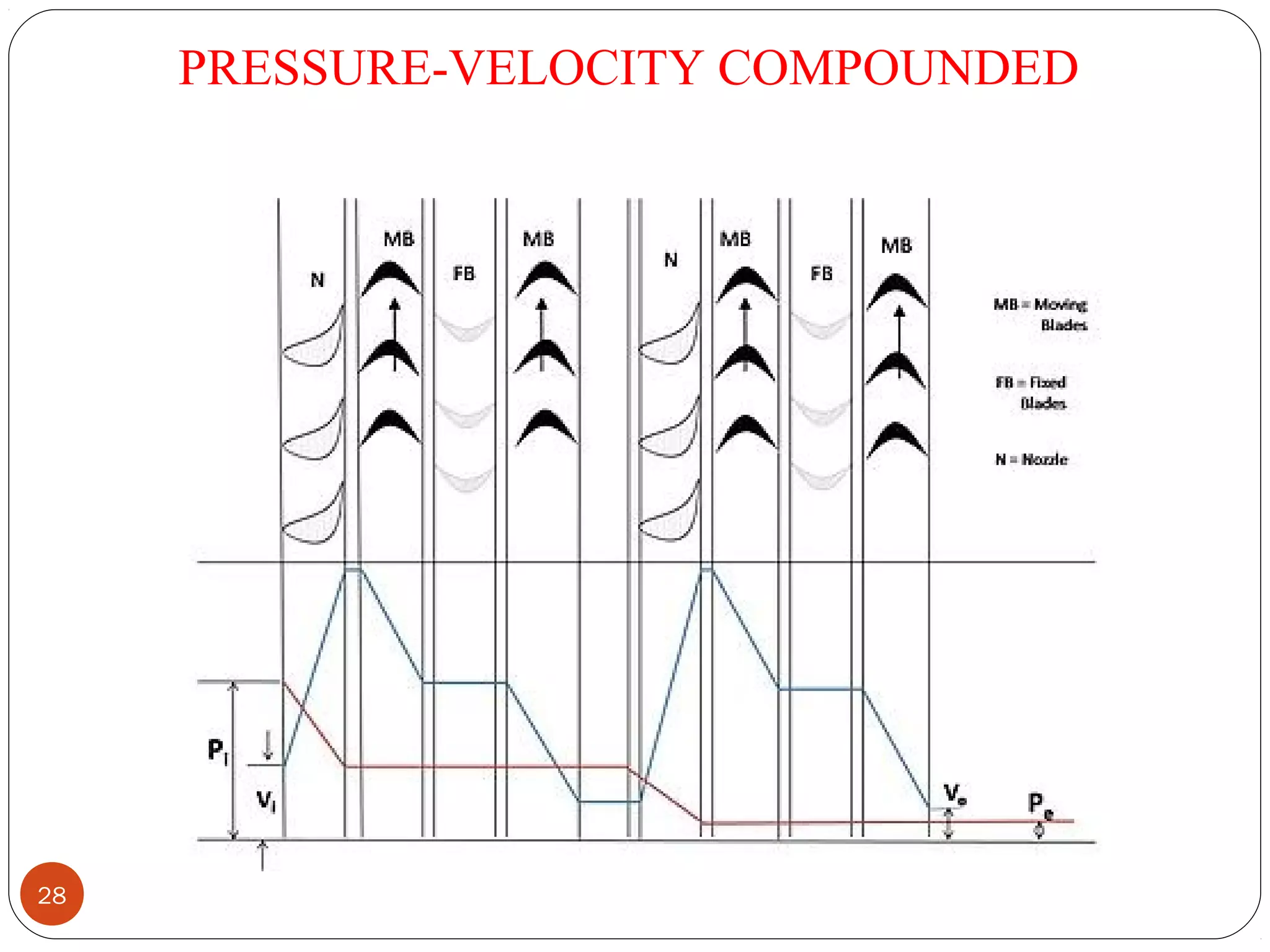
PrasadVejendla
Faculty in Mechanical
Engineering
KHIT, Guntur
1
STEAM TURBINE working
principle, types, compounding
KHIT, Guntur
Layout of Steam Power plant
2
KHIT, Guntur
A steam turbine is  a  prime  mover  in  which 
potential  energy  is  converted  into  kinetic 
energy and then to Mechanical energy.
Potential Energy
Kinetic energy
 Mechanical Energy
3 KHIT, Guntur
Steam passage
Boiler-Super heater- Economiser-
Air pre heater-Turbine-
Condenser
Water flow
Condenser-Feed water pump-
Boiler
KHIT,Guntur4
WORK IN A TURBINE VISUALIZED
5 KHIT, Guntur
Description of common types of Turbines.
1. Impulse Turbine.
2. Reaction Turbine.
The  main  difference  between  these  two 
turbines  lies  in  the  way  of  expanding  the 
steam while it moves through them. 
6 KHIT, Guntur
7 KHIT, Guntur
In the impulse turbine, the steam expands 
in  the  nozzles  and  it's  pressure  does  not 
alter as it moves over the blades. 
In  the  reaction  turbine  the  steam 
expanded  continuously  as  it  passes  over 
the blades and thus there is gradually fall in 
the  pressure  during  expansion  below  the 
atmospheric pressure. 
8
PRESSURE-VELOCITY DIAGRAM FOR A
TURBINE NOZZLE
9
ENTRANCE
HIGH THERMAL ENERGY
HIGH PRESSURE
LOW VELOCITY
STEAM INLET
EXIT
LOW THERMAL ENERGY
LOW PRESSURE
HIGH VELOCITY
STEAM EXHAUST
PRESSURE
VELOCITY
KHIT, Guntur
Simple impulse Turbine.
It the impulse turbine, the steam
expanded within the nozzle and there is no any
change in the steam pressure as it passes
over the blades
10 KHIT, Guntur
IMPULSE TURBINE PRINCIPLE
11
NOZZLE
STEAM
CHEST
ROTOR
KHIT, Guntur
12
PRESSURE-VELOCITY DIAGRAM FOR
A MOVING IMPULSE BLADE
13
VELOCITY
PRESSURE
TURBINE
SHAFT
DIRECTION OF SPIN
ENTRANCE
HIGH VELOCITY
STEAM INLET
REPRESENTS MOVING
IMPULSE BLADES
EXIT
LOW VELOCITY
STEAM EXHAUST
KHIT, Guntur
Reaction Turbine
In this type of turbine, there is a
gradual pressure drop and takes place
continuously over the fixed and moving
blades. The rotation of the shaft and drum,
which carrying the blades is the result of
both impulse and reactive force in the
steam. The reaction turbine consist of a
row of stationary blades and the following
row of moving blades
14
The fixed blades act as a nozzle which
are attached inside the cylinder and the
moving blades are fixed with the rotor as
shown in figure
When the steam expands over the
blades there is gradual increase in
volume and decrease in pressure. But
the velocity decrease in the moving
blades and increases in fixed blades with
change of direction.
15 KHIT, Guntur
Because of the pressure drops in each
stage, the number of stages required in a
reaction turbine is much greater than in a
impulse turbine of same capacity.
It also concluded that as the volume
of steam increases at lower pressures
therefore the diameter of the turbine must
increase after each group of blade rings.
PES16
REACTION TURBINE PRINCIPLE
17 STEAM CHEST
ROTOR
KHIT, Guntur
18 KHIT, Guntur
PRESSURE-VELOCITY DIAGRAM FOR
A MOVING REACTION BLADE
19
TURBINE
SHAFT
DIRECTION OF SPIN
ENTRANCE
HIGH PRESSURE
HIGH VELOCITY
STEAM INLET
REPRESENTS MOVING
REACTION BLADES
EXIT
LOW PRESSURE
LOW VELOCITY
STEAM EXHAUST
PRESSURE
VELOCITY
20
KHIT, Guntur
21
.Compounding in Steam Turbine.
The compounding is the way of
reducing the wheel or rotor speed of the
turbine to optimum value.
Different methods of compounding are:
1.Velocity Compounding
2.Pressure Compounding
3.Pressure Velocity Compounding.
In a Reaction turbine compounding can be achieved
only by Pressure compounding.22
KHIT, Guntur
Velocity Compounding:
There are number of moving blades separated by
rings of fixed blades as shown in the figure. All the
moving blades are keyed on a common shaft. When
the steam passed through the nozzles where it is
expanded to condenser pressure. It's Velocity
becomes very high. This high velocity steam then
passes through a series of moving and fixed blades.
When the steam passes over the moving blades it's
velocity decreases. The function of the fixed blades
is to re-direct the steam flow without altering it's
velocity to the following next row moving blades
where a work is done on them and steam leaves the
turbine with allow velocity as shown in diagram.23
24
Velocity Compounding
KHIT, Guntur
Pressure Compounding:
These are the rings of moving blades which are
keyed on a same shaft in series, are separated by
the rings of fixed nozzles.
The steam at boiler pressure enters the first
set of nozzles and expanded partially. The kinetic
energy of the steam thus obtained is absorbed by
moving blades. The steam is then expanded
partially in second set of nozzles where it's
pressure again falls and the velocity increase the
kinetic energy so obtained is absorbed by second
ring of moving blades.
25
26
Pressure Compounding
KHIT, Guntur
Pressure velocity compounding:
This method of compounding is the combination of two
previously discussed methods. The total drop in steam
pressure is divided into stages and the velocity
obtained in each stage is also compounded. The rings
of nozzles are fixed at the beginning of each stage and
pressure remains constant during each stage as
shown in figure. The turbine employing this method of
compounding may be said to combine many of the
advantages of both pressure and velocity staging By
allowing a bigger pressure drop in each stage, less
number stages are necessary and hence a shorter
turbine will be obtained for a given pressure drop.
27
PRESSURE-VELOCITY COMPOUNDED
28
29
Reaction turbine pressure compounding
KHIT, Guntur
30
THANK YOU
31

Steam Turbines Basics

  • 1.
    PrasadVejendla Faculty in Mechanical Engineering KHIT,Guntur 1 STEAM TURBINE working principle, types, compounding KHIT, Guntur
  • 2.
    Layout of SteamPower plant 2 KHIT, Guntur
  • 3.
    A steam turbine is  a  prime mover  in  which  potential  energy  is  converted  into  kinetic  energy and then to Mechanical energy. Potential Energy Kinetic energy  Mechanical Energy 3 KHIT, Guntur
  • 4.
    Steam passage Boiler-Super heater-Economiser- Air pre heater-Turbine- Condenser Water flow Condenser-Feed water pump- Boiler KHIT,Guntur4
  • 5.
    WORK IN ATURBINE VISUALIZED 5 KHIT, Guntur
  • 6.
    Description of common types of Turbines. 1. Impulse Turbine. 2. Reaction Turbine. The  main  difference between  these  two  turbines  lies  in  the  way  of  expanding  the  steam while it moves through them.  6 KHIT, Guntur
  • 7.
  • 8.
    In the impulse turbine, the steam expands  in  the  nozzles and  it's  pressure  does  not  alter as it moves over the blades.  In  the  reaction  turbine  the  steam  expanded  continuously  as  it  passes  over  the blades and thus there is gradually fall in  the  pressure  during  expansion  below  the  atmospheric pressure.  8
  • 9.
    PRESSURE-VELOCITY DIAGRAM FORA TURBINE NOZZLE 9 ENTRANCE HIGH THERMAL ENERGY HIGH PRESSURE LOW VELOCITY STEAM INLET EXIT LOW THERMAL ENERGY LOW PRESSURE HIGH VELOCITY STEAM EXHAUST PRESSURE VELOCITY KHIT, Guntur
  • 10.
    Simple impulse Turbine. Itthe impulse turbine, the steam expanded within the nozzle and there is no any change in the steam pressure as it passes over the blades 10 KHIT, Guntur
  • 11.
  • 12.
  • 13.
    PRESSURE-VELOCITY DIAGRAM FOR AMOVING IMPULSE BLADE 13 VELOCITY PRESSURE TURBINE SHAFT DIRECTION OF SPIN ENTRANCE HIGH VELOCITY STEAM INLET REPRESENTS MOVING IMPULSE BLADES EXIT LOW VELOCITY STEAM EXHAUST KHIT, Guntur
  • 14.
    Reaction Turbine In thistype of turbine, there is a gradual pressure drop and takes place continuously over the fixed and moving blades. The rotation of the shaft and drum, which carrying the blades is the result of both impulse and reactive force in the steam. The reaction turbine consist of a row of stationary blades and the following row of moving blades 14
  • 15.
    The fixed bladesact as a nozzle which are attached inside the cylinder and the moving blades are fixed with the rotor as shown in figure When the steam expands over the blades there is gradual increase in volume and decrease in pressure. But the velocity decrease in the moving blades and increases in fixed blades with change of direction. 15 KHIT, Guntur
  • 16.
    Because of thepressure drops in each stage, the number of stages required in a reaction turbine is much greater than in a impulse turbine of same capacity. It also concluded that as the volume of steam increases at lower pressures therefore the diameter of the turbine must increase after each group of blade rings. PES16
  • 17.
    REACTION TURBINE PRINCIPLE 17STEAM CHEST ROTOR KHIT, Guntur
  • 18.
  • 19.
    PRESSURE-VELOCITY DIAGRAM FOR AMOVING REACTION BLADE 19 TURBINE SHAFT DIRECTION OF SPIN ENTRANCE HIGH PRESSURE HIGH VELOCITY STEAM INLET REPRESENTS MOVING REACTION BLADES EXIT LOW PRESSURE LOW VELOCITY STEAM EXHAUST PRESSURE VELOCITY
  • 20.
  • 21.
  • 22.
    .Compounding in SteamTurbine. The compounding is the way of reducing the wheel or rotor speed of the turbine to optimum value. Different methods of compounding are: 1.Velocity Compounding 2.Pressure Compounding 3.Pressure Velocity Compounding. In a Reaction turbine compounding can be achieved only by Pressure compounding.22 KHIT, Guntur
  • 23.
    Velocity Compounding: There arenumber of moving blades separated by rings of fixed blades as shown in the figure. All the moving blades are keyed on a common shaft. When the steam passed through the nozzles where it is expanded to condenser pressure. It's Velocity becomes very high. This high velocity steam then passes through a series of moving and fixed blades. When the steam passes over the moving blades it's velocity decreases. The function of the fixed blades is to re-direct the steam flow without altering it's velocity to the following next row moving blades where a work is done on them and steam leaves the turbine with allow velocity as shown in diagram.23
  • 24.
  • 25.
    Pressure Compounding: These arethe rings of moving blades which are keyed on a same shaft in series, are separated by the rings of fixed nozzles. The steam at boiler pressure enters the first set of nozzles and expanded partially. The kinetic energy of the steam thus obtained is absorbed by moving blades. The steam is then expanded partially in second set of nozzles where it's pressure again falls and the velocity increase the kinetic energy so obtained is absorbed by second ring of moving blades. 25
  • 26.
  • 27.
    Pressure velocity compounding: Thismethod of compounding is the combination of two previously discussed methods. The total drop in steam pressure is divided into stages and the velocity obtained in each stage is also compounded. The rings of nozzles are fixed at the beginning of each stage and pressure remains constant during each stage as shown in figure. The turbine employing this method of compounding may be said to combine many of the advantages of both pressure and velocity staging By allowing a bigger pressure drop in each stage, less number stages are necessary and hence a shorter turbine will be obtained for a given pressure drop. 27
  • 28.
  • 29.
    29 Reaction turbine pressurecompounding KHIT, Guntur
  • 30.
  • 31.