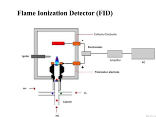
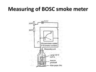
The document discusses emission formation and control. It describes the mechanisms of formation of NOx, HC, CO, and particulate emissions from engines. Methods of controlling emissions discussed include three-way catalytic converters, particulate traps, and EGR. Measurement equipment for emissions include chemiluminescence detectors for NOx and FID for HC. Smoke and particulate are measured using light extinction and filtering methods. International and national emission standards like Euro norms and Bharat Stage norms in India are also overviewed.
2. TOPICS
Formation of NOX, HC/CO mechanism – smoke and
particulate emissions – green house effect – methods
of controlling emissions – three way catalytic
converter – particulate trap – emission (HC, CO, NO
and NOX) measuring equipment – smoke and
particulate measurement – emission norms – national
and international emission standards.
3. FORMATION OF NOX MECHANISM
• Oxygen and nitrogen molecules are formed due to the peak
combustion temperature and persists during expansion and
exhaust in non-equilibrium amounts within the combustion
chamber.
• The concentration of NOx will fall with pressure and
temperature during expansion stroke to negligible level at
equilibrium condition during the exhaust valve opening.
Concentration of NOx in exhaust gases is well above
equilibrium values.
4. Nitric oxide is the major source of pollutants in industries.
Here, NOx, is produced in various ways like:
(a) Thermal NOx
(b) Fuel NOx
(c) Prompt Nox
Thermal NOx
Due to heat generation, large amount of thermal NOx is
produced, when natural gas undergoes combustion process. But
in coal fuel it contains nitrogen.
5. When the combustion takes place in coal, minimum amount of
NOx is produced. Thermal NOx occurs when the temperature is
in the process of more than 1600°C. This is due to the
disassociation of nitrogen and oxygen molecules.
Fuel NOx
Fuel NOx is produced when the fuel which contains nitrogen
undergoes high combustion temperature. For example, coal fuel
and oil fuels undergo this type of NOx formation. During
combustion, the nitrogen bound in the fuel is released as a free
radical and forms free nitrogen and nitrogen oxides
6. In the combustion stage, the volatile nitrogen is first oxidized, then
it reacts with the inter mediants and nitric oxide is formed.
(c) Prompt Nox
Reaction of nitrogen with the atmosphere gives out prompt
NOx. This is then reacts with C, CH and CH which is delivered
from fuel. This type of NOx occurs in the earlier stage of the
combustion processes. This type of NOx formed when the
oxygenated fuels such as biodiesel is combusted under low
temperature
7. The formation of NOx concentration in the exhaust gas from
S.I engine is reduced by
(a) Decreasing the oxygen available by decreasing the air fuel
ratio and homogeneity of the mixture.
(b) Decreasing the combustion temperature.
(i) Increasing valve overlap
(ii) By adding exhaust gas to the fresh charges
(iii) Avoiding knocking combustion
(iv) Reducing the spark timing
(v) Decreasing the compression ratio, charge temperature, speed
and mixture pressure.
8. • Carbon monoxide is emitted with the exhaust gas due to the
incomplete combustion of carbon. This incomplete combustion
occurs due to the dissociation process.
• The measured concentration of CO is greater than the
equilibrium concentrations. CO concentration does not drop to
zero when the mixture is chemically correct and leaner.
FORMATION OF CARBON MONOXIDE
MECHANISM
9. FORMATION OF HYDROCARBON
MECHANISM
Hydrocarbon level in the exhaust gas is in the range of 1000-3000
ppm. HC emission rises rapidly as the mixture becomes
substantially richer than the stoichiometric.
In lean mixture, HC emission can rise rapidly due incomplete
combustion of misfire in a fraction of the engine’s operating cycle.
HC emission formation mechanisms are dealt as follows;
•Leaving a layer of unburned air fuel mixture to adjacent wall is
known as flame quenching.
•Crevice volume plays a vital role in HC emission.
10. • Carbon particles suspended in the exhaust gas is known as
smoke. It is generated when the engine is accelerated (or)
decelerated. The smoke colour determines the problem of the
engine.
Different colours of smoke are produced while using a diesel
engine.
White smoke will arise when the fuel is not fully burnt (or) due
to the cold engine(or) leakage in the coolant.
Black smoke is caused due to extremely rich air fuel mixture
White smoke is caused due to cool engine and cool leakage.
SMOKE EMISSION
11. .
SMOKE FORMATION MECHANISM
Fuel droplet is made up of several layers. After ignition,
the process first starts at the outer layer of the fuel droplet. As
soon as the outer droplet of the ignition heat is generated t it
passes to core of the fuel droplet. At the core, the oxygen
content is little (or) no oxygen. The hydrocarbons get cracked
into hydrogens and carbons. Hydrogen has more affinity
towards oxygen when compared with carbon.
12. .
FACTORS INFLUENCING SMOKE PRODUCTION
Engine details
Fuel Factors
Engine Maintenance
Engine details
– Engine design
• Quantity of fuel introduced
• Mixing ratio of the fuel
• Heat due to uncontrollable combustion process
– Inlet port design
• Movement of air
• Time intensity for premixing, and burning soot.
• Heat loss on the walls
13. Fuel Factors
• Ignition delay and fuel mixing completely depends on the cetane number.
• Ignition of fuel depends on the fuel injection quality Fuel should be
ignited slowly.
• Viscosity of fuel affects the penetration of the heat to its core.
Engine Maintenance
– Injection System
• Blocks at the nozzle holes should be reduced.
• Checking the piston rings, cylinder chambers, pump plungers,
fuel injector needle, fuel filters, etc.
– Loss of compression due to worn out piston rings, seating valves,
fuel intake system, etc.
14. • Small, solid particles and liquid droplets are collectively termed as
particulates. These are present in the atmospheric fairly large numbers
and sometimes pose a serious air pollution. The size of the particulate
is the major factor Particulate range in diameter of 0.0002 mm with
life time varies for a few seconds to several months. Its life time
depends on the settling rate, size, density and turbulence of air.
Sources of Particulates
• Natural sources
• Man-made factors
PARTICULATE EMISSION
15. GREEN HOUSE EFFECT
• Carbon dioxide, although a relatively insignificant non- pollutant
species in the atmosphere, is of serious environmental concern.
• Among the constituents of the atmosphere, only carbon dioxide
and water vapour strongly absorb infrared radiation and
effectively block a large fraction of the earth's emitted radiation.
The radiation thus absorbed by CO2 and H₂O vapour is partly re-
emitted to the earth's surface. The net result is that the earth's
surface gets heated up by a phenomenon called Green house
effect.
18. EMISSION CONTROL SYSTEMS
• Fuel system optimization.
• Control of ignition timing.
• Exhaust gas recirculation.
• Engine design modification.
• Exhaust gas after treatment using catalysts.
• Fuel modification.
19. Fuel system optimization
• Fuel system may be optimized by using electronic fuel injection.
o Equal distribution of mixture to all the cylinders.
o Atomization of fuel for better mixing.
o Avoiding variance in the idling speed.
Exhaust gas recirculation system (EGR) System
• In this method, a little amount of exhaust gas is sent into the engine
cylinder. This reduces the combustion temperature and thereby
prevents NOx pollution.
20. • Evaporative emission control system
Evaporative emission control system is achieved by adsorption.
Positive Crankcase Ventilation (PCV) system keeps the engine
crankcase fumes out of atmosphere.
• Catalytic converter
Thermal reactor for burning and chemically changing the
harmful exhaust by products into harmless substances. These harmful
toxic substances in the S.I engine exhaust gases are mostly made
harmless by means of catalytic converters. The catalytic converter is
installed between the exhaust manifold and muffler in the exhaust
system.
21. THREE WAY CATALYTIC CONVERTER
• The catalytic converter consists of a catalytic unit contained in a metal
canister which surrounds the ceramic catalyst unit with a steel sheet.
To avoid corrosion, the converter shell is made up of a special
stainless steel. In between the steel shell and the exterior of the
catalytic unit, there is a compliant layer which exerts sufficient force
to prevent movement within the canister and it compensates for the
differences in thermal expansion between the catalyst and the metal
shell.
23. PARTICULATE TRAPS
• An exhaust treatment technology that substantially reduces diesel
engine particulate emissions is the trap oxidiser. A temperature-
tolerant filter or trap removes the particulate material from the exhaust
gas, the filter is then "cleaned off" by oxidizing the accumulated
particulates.
This has great disadvantage for practical use because
• The filter, even when clean, increases the pressure in the exhaust
system
24. An exhaust treatment technology that substantially reduces diesel
engine particulate emissions is the trap oxidiser. A temperature-tolerant
filter or trap removes the particulate material from the exhaust gas, the
filter is then "cleaned off" by oxidizing the accumulated particulates.
This has great disadvantage for practical use because
The filter, even when clean, increases the pressure in the exhaust
system.
Types of particulate filters include the following:
• Ceramic monolith
• Alumine - coated wire mesh
• Ceramic foam
• Ceramic fiber mat
• Woven silica-fiber rope wound on a porous tube
25. EXHAUST GAS RECIRCULATION (EGR)
• NOx emission can be easily reduced by keeping the
combustion chamber temperature down. This reduces
the engine's thermal efficiency.
• The simplest practical method of reducing maximum
flame temperature is to dilute the air-fuel mixture with a
non- reacting parasite gas. This gas absorbs energy
during combustion without contributing any energy
input. This leads to the lower flame temperature.
27. INDIAN DRIVING CYCLE
• The driving cycle of any country is the probable plot of the vehicle
speed right from the start of the engine through its journey over a
prescribed time
28. EMISSIONS
From the point of view of pollution control, measurement of
emissions from engines is very important Emissions may be
divided into two groups, viz., invisible and visible emissions.
The exhaust of an engine may contain more of the following
• carbon dioxide
• water vapour
• oxides of nitrogen
• unburnt hydrocarbons
30. The chemiluminescence method offers the best results whenever the
difficult analysis of the tiny molecule NO in gases is required.
Chemiluminescence method allows to detect extremely low
concentrations of NO, being not only fast but also very sensitive and not
specified.
The reaction scheme of NO and O3 by chemiluminescence is as follows:
NO +O3→NO₂+O2 (1)
NO + O3→ NO2* +O2 (2)
NO2* →NO2 +hv (3)
NO2 +M→NO2 + M (4)
32. •The radiation emission is in the wavelength 600nm and 3000nm
with an intensity maximum at approximately 1200nm. This
chemiluminescence signals is detected photoelectrically.
• When O3 is present in excess; the signal is proportional to the
NO concentration of the sample gas. The length portion of the
NO2 * returns to ground state without radiation emission, due to
collisions with other molecules (M) i.e., in order to enhance the
light yield, the pressure in the reaction chamber is reduced.
33. •Quenching is an unwanted phenomenon, the extent to which it occurs
depends on the character of the colloiding molecule M. For instance with
(H2O) and carbon dioxide (CO2) quench NO chemiluminescence more
effectively than nitrogen (N2) and oxygen (O2).
•In order to measure NO₂ in the sample gas, it has to be converted into
NO. To accomplish this chemical reduction, the sample gas is passed
through a converter which is heated to more than 300°C.
34. EXHAUST GAS ANALYSERS
For measuring the gaseous pollutants two analysers are used. They
are:
•Non-Dispersive Infrared Gas Analyser (NDIR) (to measure CO)
•Flame Ionization Detector (FID) (to measure HC)
40. SMOKE MEASUREMENT
Exhaust gas, i.e. smoke, is measured by two methods.
• Light extinction.
• Continuous and spot filtering
41. Light Extinction Smoke Meter
• Here photoelectric cell is used to measure the smoke. An
extinction of light is passed through the sample stream of
exhaust gas. Here the photoelectric cell is lightened by a
tungsten filament bulb after traversing a 45 cm column of
exhaust gas. Zero reading on the scale of the output meter
occurs with clean air tube and a reading of 100 on the scale
corresponding to complete observation of the light. 1% of light
absorbed is represented as an hartidge smoke unit.
43. Continuous & Spot Filtering Smoke Meter
•In continuous filtering smoke meter, the smoke is continuously
passed through a moving strip of filter paper and collecting particles.
Calibration is facilitated by adjusting the sample rate, tape speed, and
working, etc.
• In spot filtering smoke meter, photoelectric device is used to
measure the smoke rate. Smoke is continuously passed through a
fixed filter paper
45. • The exhaust of CI engines contains solid carbon soot particles that
are generated in the fuel-rich zones within the cylinder during
combustion.
• These are seen as exhaust smoke and cause an undesirable odorous
pollution. Maxi- mum density of particulate emissions occurs when the
engine is under load at WOT. At this condition maximum fuel is injected
to supply maximum power, resulting in a rich mixture and poor fuel
economy. This can be seen in the heavy exhaust smoke emitted when a
truck or railroad locomotive accelerates up a hill or from a stop.
46. EMISSION NORMS (EURO AND BS)
Emission norms for automobiles are the standards set by the authority of
differes countries focusing on controlling the amount of pollutants
released into the environment from automobiles. Each stage of emission
standards specifically describes the amount of pollutants from vehicles
such as carbon monoxide (CO), nitrogen oxides (NO), sulphur dioxide,
con dioxide (CO), hydrocarbons (HC) and particulates which can be
emitted from an automobile into the environment. These regulatory
standards differ from nation to nation. But the aim is common to control
the environmental pollution.
47. Parameters determining emission from vehicles
While each one of the following four factors have direct
environmental implications, the vehicle and fuel systems have
to be addressed as a whole and jointly optimized in order to
achieve significant reduction in emission.
• Vehicular technology
• Fuel quality
• Inspection& maintenance of in-use vehicles
• Road and traffic management.
48. Setting Emission Norms
The focus here is on simulation of actual driving versus
assumed driving pattern in a cycle based on long
observation and trials on road. In simulation, the vehicle is
"exercised" on "tread mill" called chassis dynamometer
replicating the assumed driving- pattern of the country.
This is called the driving cycle of the country. The
emissions are measured over the cycle and the results
computed to give mass emissions.
49. Euro Norms
• Euro norms refer to the permissible emission levels for both
petrol and diesel vehicles, which have been implemented in
Europe. In European Union member countries, some
automobile manufacturing countries in Asia and Africa and
several non- manufacturing countries imports vehicles which
have adopted European emission standard as their standards.
European standards are set on the classification of vehicles
based on their weight and engine capacity
50. BS Norms
•Bharat Stage (BS) emission standards are emission standards instituted
by the Government of India to regulate the output of air pollutants from
internal combustion engine equipment, including motor vehicles. The
standards and the timeline for implementation set by the Central
Pollution Control Board under the Ministry of Environment & Forests
•India is using European emission norms with a time lag of five years
with BS-IV norm currently applicable in 50 cities where the required
grade of fuel is available while the rest of the country follows BS-III
standards. But many vehicles are BS-1 and BS-11 compliant and more
polluting.
51. Overview of the Emission Norms in India:
•1991-Idle CO Limits for Gasoline Vehicles and Free Acceleration
Smoke for Diesel Vehicles, Mass Emission Norms for Gasoline Vehicles.
•1992- Mass Emission Norms for Diesel Vehicles.
•1996 -Revision of Mass Emission Norms for Gasoline and Diesel
Vehicles. mandatory fitment of Catalytic Converter for Cars in Metros
on Unleaded Gasoline.
•1998-Cold Start Norms Introduced.
•2000- India 2000 (Eq. to Euro 1) Norms. Modified IDC (Indian Driving
Cycle), Bharat Stage II Norms for Delhi,
•2001- Bharat Stage II (Eq. to Euro II) Norms for All Metros, Emission
Norms for CNG & LPG Vehicles:
52. •2003 Bharat Stage II (Eq. to Euro II) Norms for 11 major cities.
•2005- From 1 April Bharat Stage III (Eq. to Euro III) Norms for 11
major cities.
•2010- Bharat Stage III Emission Norms for 4-wheelers for entire
country whereas Bharat Stage-IV (Eq. to Euro IV) for 11 major cities.
•2017 – Bharat Stage IV norms for all vehicles.
•2018 - Bharat Stage VI fuel norms from 1 April 2018 in Delhi
instead of 2020.
•2020 – Bharat Stage VI fuel norms from 1 April 2020 nationwide
switching India to world's cleanest diesel and petrol.
•2023 - Bharat Stage VI Second Phase Fuel norms from 1 April 2023
have only Petrol also called RDE norms with e20 fuels.