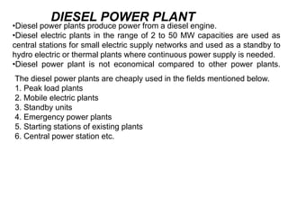
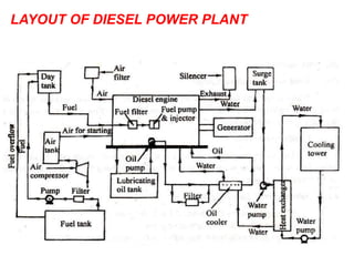
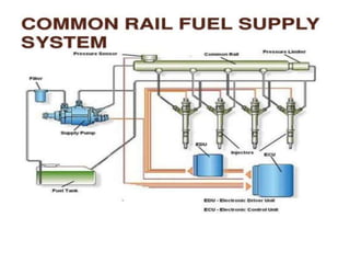
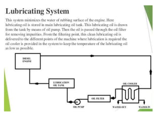
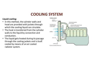
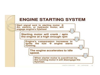
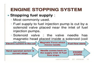
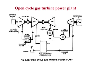
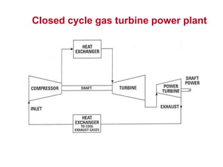
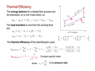
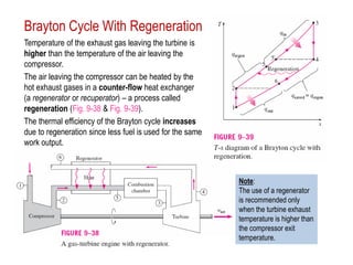
8. •Diesel power plants produce power from a diesel engine.
•Diesel electric plants in the range of 2 to 50 MW capacities are used as
central stations for small electric supply networks and used as a standby to
hydro electric or thermal plants where continuous power supply is needed.
•Diesel power plant is not economical compared to other power plants.
DIESEL POWER PLANT
The diesel power plants are cheaply used in the fields mentioned below.
1. Peak load plants
2. Mobile electric plants
3. Standby units
4. Emergency power plants
5. Starting stations of existing plants
6. Central power station etc.
10. a)Engine
•Engine is the heart of a diesel power plant.
•Engine is directly connected through a gear box to the generator.
•Generally two-stroke engines are used for power generation.
• Now a days, advanced super & turbo charged high speed engines are
available for power production.
b)Air supply system
•Air inlet is arranged outside the engine room.
Air from the atmosphere is filtered by air filter and conveyed to the inlet
manifold of engine.
• In large plants Supercharger/turbocharger is used for increasing the
pressure of input air which increases the power output.
c) Exhaust System
This includes the silencers and connecting ducts. The heat content of the
exhaust gas is utilized in a turbine in a turbocharger to compress the air
input to the engine.
d) Fuel System
Fuel is stored in a tank from where it flows to the fuel pump through a filter.
Fuel is injected to the engine as per the load requirement.
11. e)Cooling system
This system includes water circulating pumps, cooling towers, water filter etc.
Cooling water is circulated through the engine block to keep the temperature
of the engine in the safe range.
f) Lubricating system
Lubrication system includes the air pumps, oil tanks, filters, coolers and pipe
lines. Lubricant is given to reduce friction of moving parts and reduce the
wear and tear of the engine parts.
g)Starting System
There are three commonly used starting systems, they are;
1) A petrol driven auxiliary engine,
2) Use of electric motors,
3)Use of compressed air from an air compressor at a pressure of 20 Kg/cm2
h)Governing system
The function of a governing systemis to maintain the speed of the engine
constant irrespective of load on the plant. This is done by varying fuel
supply to the engine according to load.
12. Advantages of diesel power plants
1.More efficient than thermal plant
2.Design, Layout etc are simple and cheap
3.Part load efficiency is very high
4.It can be started quickly
5.Simple & easy maintenance
6.No problem with fuel & dust handling
7.It can be located in the heart of town
8.Less cooling water required.
Disadvantages
1.There is a limitation for size of a diesel engine
2. Life of plant is comparatively less
3.Noise pollution is very high
4.Repair cost is very high
5.High lubrication cost
13. DIESEL ENGINE POWER PLANT
• ENGINE
• AIR INTAKE SYSTEM
• EXHAUST SYSTEM
• FUEL SYSTEM
• COOLING SYSTEM
• LUBRICATING SYSTEM
• STARTING OF ENGINE
14. Fuel Injection System`
Functions
1. Filter the fuel
2. Meter the correct quantity of injected fuel
3. Time the injection process injected
4. Regulate the fuel supply
5. Secure fine atomization of fuel
6. Distribute the atomized fuel in Combustion
chamber
15. Oil atomization
• Air blast fuel atomization ,Compressed air at
70 bar used to atomize & inject fuel. For this
Compressor and storage tank required which
is expensive.
• Solid Injection : Fuel oil is forced to flow thro
spray nozzles at a pressure of above 100 bar.
a) Common rail injection system
b) Individual pump injection system
c) Distributor system.
16. Common Rail Injection system
• A single pump supplies fuel under pressure to
fuel header or common rail.
• High pressure in the header forces the fuel to
each of the nozzles located in the cylinder
• At the proper time, a mechanically operated
valve allows fuel to enter cylinder thro nozzle
• The amount of fuel entering cylinder is
regulated by varying the length of the push
rod stroke.
17.
18. Fuel oil injection system (contd.)
• Individual pump injection system
• Distributor system
19.
20. Cooling & Lubricating System
• THERMO SIPHON COOLING
• THERMOSTAT COOLING
• Splash lubricating system
• Bypass type wet sample lubrication
21.
22.
23.
24.
25.
26. Classification of gas turbines :
• Gas turbines are classified according to three factors , These are :
1. Combustion process
2. Path of working substance
3. Action of combustion gases in turbine
27. Classification of Gas turbine
Combustion process Path of Gases
Action of
Gases
Const.
volume
Const. pressure
Impulse Turbine
Impulse-Reaction
Turbine
Open Cycle GT Closed Cycle GT
Semi Closed Cycle GT
30. Advantages of gas turbine power plant
Storage of fuel requires less area and
handling is easy.
The cost of maintenance is less.
It is simple in construction. There is no need
for boiler, condenser and other accessories as in
the case of steam power plants.
Cheaper fuel such as kerosene , paraffin,
benzene and powdered coal can be used which
are cheaper than petrol and diesel.
Gas turbine plants can be used in water
scarcity areas.
Less pollution and less water is required.
31. Disadvantages of gas turbine power plant
66% of the power developed is used to drive
the compressor. Therefore the gas turbine unit
has a low thermal efficiency.
The running speed of gas turbine is in the
range of (40,000 to 100,000 rpm) and the
operating temperature is as high as 1100 –
12600C. For this reason special metals and
alloys have to be used for the various parts of
the turbine.
High frequency noise from the compressor is
objectionable.
32. The open gas-turbine cycle can be
modelled as a closed cycle, using
the air-standard assumptions (Fig.
9–30).
The compression and expansion
processes remain the same, but the
combustion process is replaced by
a constant-pressure heat
addition process from an external
source.
The exhaust process is replaced by
a constant-pressure heat
rejection process to the ambient
air.
Closed Cycle Model
33. The ideal cycle that the working fluid
undergoes in the closed loop is the Brayton
cycle. It is made up of four internally
reversible processes:
1-2 Isentropic compression;
2-3 Constant-pressure heat addition;
3-4 Isentropic expansion;
4-1 Constant-pressure heat rejection.
The T-s and P-v diagrams of an ideal Brayton
cycle are shown in Fig. 9–31.
Note: All four processes of the Brayton cycle
are executed in steady-flow devices thus,
they should be analyzed as steady-flow
processes.
The Brayton Cycle
34. Thermal Efficiency
The energy balance for a steady-flow process can
be expressed, on a unit–mass basis, as
The heat transfers to and from the working fluid
are:
The thermal efficiency of the ideal Brayton cycle,
is the pressure ratio.
where
Constant specific heats
35. Brayton Cycle With Regeneration
Temperature of the exhaust gas leaving the turbine is
higher than the temperature of the air leaving the
compressor.
The air leaving the compressor can be heated by the
hot exhaust gases in a counter-flow heat exchanger
(a regenerator or recuperator) – a process called
regeneration (Fig. 9-38 & Fig. 9-39).
The thermal efficiency of the Brayton cycle increases
due to regeneration since less fuel is used for the same
work output.
Note:
The use of a regenerator
is recommended only
when the turbine exhaust
temperature is higher than
the compressor exit
temperature.
36. Compare Open cycle and Closed cycle Gas turbines
Open cycle:
1. Warm-up time. Once the turbine is brought up to the rated speed by the starting
motor and the fuel is ignited, the gas turbine will be accelerated from cold start to full
load without warm-up time.
2. Low weight and size. The weight in kg per kW developed is less.
3. Open cycle plants occupy comparatively little space.
4. Open-cycle gas turbine power plant, except those having an intercooler, does not
require cooling water.
5. The part load efficiency of the open cycle plant decreases rapidly as the
considerable percentage of power developed by the turbine is used to drive the
compressor.
6. The open-cycle gas turbine plant has high air rate compared to the other cycles,
therefore, it results in increased loss of heat in the exhaust gases.
37. Compare Open cycle and Closed cycle Gas turbines
Closed cycle:
1. The machine can be smaller and cheaper than the machine used to develop the
same power using open cycle plant.
2. The closed cycle avoids erosion of the turbine blades due to the contaminated
gases and fouling of compressor blades due to dust. Therefore, it is practically free from
deterioration of efficiency in service.
3. The need for filtration of the incoming air which is a severe problem in open cycle plant
is completely eliminated.
4. The maintenance cost is low and reliability is high due to longer useful life.
5. The system is dependent on external means as considerable quantity of cooling water
is required in the pre-cooler.
6. The response to the load variations is poor compared to the open-cycle plant
38. Gas Turbines
• Gas turbines also called combustion turbines, a type
of IC engine in which burning of an air-fuel mixture
produces hot gases that spin a turbine to produce
power.
• It is the production of hot gas during fuel
combustion, not the fuel itself that the gives gas
turbines the name.
• Combustion occurs continuously in gas turbines, as
opposed to reciprocating IC engines, in which
combustion occurs intermittently.
39. Working
They Work On Brayton Cycle.
Air is compressed(squeezed) to high pressure by a compressor.
Then fuel and compressed air are mixed in a combustion
chamber and ignited.
Hot gases are given off, which spin the turbine wheels
41. Components Of Gas Turbine
Gas turbines have three main parts:
i) Air compressor
ii) Combustion chamber
iii) Turbine
42. Gas turbine power plant
Working principle :
Air is compressed(squeezed) to high pressure by a
compressor.
Then fuel and compressed air are mixed in a combustion
chamber and ignited.
Hot gases are given off, which spin the turbine wheels.
43. Description:
Gas turbines burn fuels such as oil, nature gas and
pulverized(powdered) coal.
Gas turbines have three main parts:
i) Air compressor
ii) Combustion chamber
iii) Turbine
44. Air compressor:
The air compressor and turbine are mounted at
either end on a common shaft, with the combustion
chamber between them.
Gas turbines are not self starting. A starting motor
is used.
The air compressor sucks in air and compresses it,
thereby increasing its pressure.
45. Turbine:
Hot gases move through a multistage gas
turbine.
Like in steam turbine, the gas turbine also has
stationary and moving blades.
The stationary blades
guide the moving gases to the rotor blades
adjust its velocity.
The shaft of the turbine is coupled to a
generator.
46. Applications of gas turbine:
drive pumps, compressors and high speed cars.
aircraft and ships.
Power generation (used for peak load and as stand-
by unit).
47. Combined Cycle Power Plants
The maximum steam temp. in a power cycle
does not exceed 600 deg.C, although the
temp. in a dry bottom pulversied coal furnace
is about 1300 deg. C.
There fore , there is great thermal
irreversibility and a decrease of availability
because of heat transfer from combustion
gases to steam through a such large temp.
differences.
48. • By superposing a high temp. power plant as
a topping unit to the steam power plant, a
higher energy conversion efficiency from fuel
to electricity could be achieved,
• since the combined plant operates through a
higher temp. range.
49. • Combined cycle plants may be of the
following types
Gas Turbine- Steam Turbine plant
MHD- Steam Plant
Thermionic – Steam plant
Thermoelectric – Steam plant.
50. • The air standard cycle for a gas turbine power
plant is the Brayton Cycle, which like Rankine
cycle also consists of two reversibile
adiabatics and two reversible isobars,
• but in Brayton cycle working fluid does not
undergo phase change where as in Rankine
cycle, the working fluid is water gets phase
change as steam.
51. • To overcome GT plant’s low cycle efficiency, a
Gas Turbine may be used in conjunction with
a steam turbine plant in an utility base load
station to offer the utilities the gas turbine
advantages of quick starting and stopping
and permit flexible operation of the
combined plant over a wide range of loads.
55. IGCC
• An integrated gasification combined cycle (IGCC) is a technology that
uses a high pressure gasifier to turn coal and other carbon based fuels
into pressurized gas—synthesis gas . Impurities removed from the
syngas prior to the power generation cycle.
• Some of these pollutants, such as sulfur, can be turned into re-usable
byproducts through the Claus Process. This results in lower emissions of
Sulfur dioxide, mercury and in some cases Carbon dioxide.
• With additional process equipment, a water gas reaction can increase
gasification efficiency and reduce carbon monoxide emissions by
converting it to carbon dioxide. The resulting carbon dioxide from the
shift reaction can be separated, compressed, and stored through
sequestration.
• Excess heat from the primary combustion and syngas fired generation is
then passed to a steam cycle, similar to a combined cycle gas turbine.
• This process results in improved thermodynamic efficiency compared to
conventional pulverized coal combustion.
57. • The plant is called integrated because
• the syngas produced in the gasification section is used as fuel for
the gas turbine in the combined cycle and
• the steam produced by the syngas coolers in the gasification
section is used by the steam turbine in the combined cycle.
• In this example the syngas produced is used as fuel in a gas
turbine which produces electrical power. In a normal combined
cycle, so-called "waste heat" from the gas turbine exhaust is used
in a Heat Recovery Steam Generator (HRSG) to make steam for
the steam turbine cycle.
• An IGCC plant improves the overall process efficiency by adding
the higher-temperature steam produced by the gasification
process to the steam turbine cycle. This steam is then used in
steam turbines to produce additional electrical power.
58. Advantages & Disadvantages of IGCC
• IGCC plants are advantageous in comparison
to conventional coal power plants due to
their high thermal efficiency, low non-carbon
greenhouse gas emissions, and capability to
process low grade coal.
• The disadvantages include higher capital and
maintenance costs, and the amount of CO2
released without pre-combustion capture.
59. Process of IGCC
• The solid coal is gasified to produce syngas, or
synthetic gas.
• Syngas is synthesized by gasifying coal in a closed
pressurized reactor with a shortage of oxygen.
• The shortage of oxygen ensures that coal is broken
down by the heat and pressure as opposed to
burning completely.
• The chemical reaction between coal and oxygen
produces a product that is a mixture of carbon and
hydrogen, or syngas.
CxHy + (x/2)O2 → (x)CO2 + (y/2)H2
60. • The heat from the production of syngas is
used to produce steam from cooling water
which is then used for steam turbine
electricity production.
• The syngas must go through a pre-
combustion separation process to remove
CO2 and other impurities to produce a more
purified fuel.
Editor's Notes
***Gas turbines can utilize a variety of fuels, including natural gas, fuel oils, and synthetic fuels.