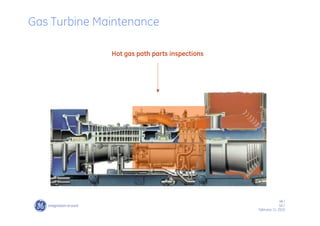
The document discusses gas turbine maintenance planning and procedures. It emphasizes the importance of maintenance for productivity and profitability. It provides details on inspection types and frequencies based on operating factors like fuel type, load, starts and trips. Guidelines are given for combustion inspections, hot gas path inspections, and calculating customized inspection intervals based on unit-specific operation.
The document discusses gas turbines used at an NFL power plant in Vijaipur. It provides details on the models, ratings, and loads of three gas turbine generators (GTGs). It then discusses heavy duty gas turbines from GE in terms of their configurations, frame sizes, speeds, and applications. The rest of the document goes into extensive technical details about the components, workings, inspections, and factors that influence gas turbines, including compressors, combustion systems, turbines, bearings, and more.
This document provides an overview of gas turbine fundamentals and components. It discusses the gas turbine course topics which include the lubrication oil system, hydraulic oil system, trip oil system and other key systems. It then summarizes the components and operation of a GE 9001E gas turbine, including descriptions of the compressor, combustion system, turbine, bearings and lubrication oil system.
This document summarizes the key components and operation of a gas turbine located at the Panipat Refinery. It includes 5 gas turbines made by BHEL/GE that are MS 6000 single shaft design units with a base load capacity of 30.77 MW each. The major components discussed include the compressor, combustors, turbine section, casings, bearings, and cooling/sealing systems. It also provides details on the basic principles of how a gas turbine works by continuously drawing in air, compressing it, adding fuel to increase its energy, directing the high pressure gas to expand through a turbine, and exhausting the low pressure gas.
Gas Turbine Training Power Point -SampleAli Rafiei
The document provides an overview of gas turbine evolution and components. It discusses the development of axial compressors and turbines from the 18th century ideas of John Barber and John Dumball. It then summarizes the key components of modern gas turbines, including compressors, combustion chambers, turbines, lubrication systems, and controls. Examples are given for Siemens SGT600 components like the compressor, combustion chamber, and control modes.
This document provides instructions for performing a heavy-duty gas turbine combustion inspection. It lists the typical combustion hardware that needs to be inspected, including combustion liners, endcovers, fuel nozzles, transition pieces, cross fire tubes, and flow sleeves. Standard inspection intervals are every 8,000 hours or 900 starts. The inspection involves removing, inspecting, and repairing combustion components. Replacement parts should be available for installation after the inspection is complete. A series of 18 operations is outlined to remove the various combustion and fuel system components to allow for inspection.
This document provides information about how gas turbine engines work and their applications. It first describes the basic components and process of a simple cycle gas turbine, which involves compression, combustion, and expansion stages. It then discusses the key components in more detail, including axial compressors and turbines, and different combustor designs. The document outlines common performance characteristics like efficiency variations with load and ambient temperature. Finally, it lists some common industrial and power generation applications for gas turbines and how they are used for base load, peak load, and standby operations.
Thermal Power Plant Simulator, Cold, warm and Hot rolling of Steam TurbineManohar Tatwawadi
The presentation describes the cold rolling, warm rolling and hot rolling and synchronising of steam turbine. The Temperature Matching Chart for Turbine metal and Steam is also discussed in the presentation
For all the Gas Turbine lovers, the following presentation is aimed to cover the Major Inspection of the Gas Turbine (GE, Fr-9E). It is weaved with all of the major activities involved in MI, tools and tactics with addition of the reference values. Each activity is described with aid of pictures for detailed understanding.
The document discusses gas turbine components and operation. It describes the main parts of a gas turbine as the compressor, combustion chamber, and turbine. The compressor draws in and pressurizes air, which is then heated in the combustion chamber by adding and burning fuel. The high-energy combustion gases expand through the turbine, which drives the compressor and generates power. Startup procedures are discussed, including the use of blow-off valves to relieve compressor pressure and prevent surge during initial acceleration.
Gas turbines work by compressing air, heating it through combustion, and using the expanding hot gases to power a turbine. The key components are a compressor, combustion chamber, and turbine. In the compressor, air is compressed which is then mixed with fuel and ignited in the combustion chamber. The hot gases expand through the turbine, which converts the energy to power the compressor and provide output work to drive loads like generators or propellers. Variations include closed cycle systems which recirculate working fluid through a heat exchanger. Gas turbines have high power-to-weight ratios but lower efficiencies compared to reciprocating engines.
This document provides an overview of the scope of work for overhauling a turbine. It outlines the preparation, alignment checks, disassembly, non-destructive testing, fact-finding, reassembly, and commissioning processes. The specific tasks listed include opening bearing pedestals, uncoupling various components, checking alignments, disassembling the high pressure and low pressure turbines and valve blocks, performing non-destructive testing, inspecting individual parts, reassembling components, and conducting final alignment checks and commissioning. Detailed procedures are provided for selected tasks such as opening bearing pedestals and uncoupling various turbine sections.
Gas turbine engines derive their power from burning fuel in a combustion chamber and using the fast flowing combustion gases to drive a turbine in much the same way as the high pressure steam drives a steam turbine.
The gas turbine is the engine at the heart of the power plant that produces electric current. A gas turbine is a combustion engine that can convert natural gas or other liquid fuels to mechanical energy. This energy then drives a generator that produces electrical energy.
In a gas turbine, gas is ignited under pressure and combustible high-pressure, high-temperature gases are produced. The combustible gases power a turbine, which in turn powers a generator. In a boiler power plant, electricity is generated by heating water to produce steam which, via a turbine, powers a generator.
The document provides information about GE's MS 5002 C gas turbine customized for Burlington Resources MLN 405 Project. It contains proprietary information for customer training purposes only. The manual covers theory of operation, maintenance, and drawings of the gas turbine. It was prepared by Elena Casini of GE Oil & Gas and approved by Cesare Sordi, the customer training manager, on March 19, 2007 for the specific customer and job. The manual has sections on theory of operation, operation, maintenance, and drawings of the gas turbine.
This document provides an overview of centrifugal compressors. It begins with introductions to potential and kinetic energy as they relate to compression. It then discusses dynamic compressors like centrifugal and axial compressors. The document outlines the major parts of compressors like casings, impellers, diffusers, and seals. It also describes the cooling, lubrication, and safety systems that support compressor operation. Finally, it discusses operating characteristics, configurations like series and parallel, and performance features of compressors.
Centrifugal compressors work by imparting kinetic energy to a gas stream using an impeller, converting the dynamic energy into increased static pressure. They have advantages like high throughput capacity and efficiency over a wide operating range, but also disadvantages like discharge pressure limitations. Key components include impellers, diffusers, volutes, casings, shafts, bearings, and seals. Surge, a dangerous condition where flow reverses rapidly, must be controlled. Compressors can operate alone or in multi-stage arrangements with intercoolers. Common drivers are steam turbines, electric motors, and gas turbines.
This document provides an overview of a gas turbine generator system. It describes the key components and sections of the gas turbine, including the accessory, air inlet, compressor, combustion, turbine and exhaust sections. It outlines the gas turbine cycle and flow process. It also summarizes the startup steps and possible tripping causes for the gas turbine system.
The document provides information on governing systems and common problems encountered. It discusses:
1. The key components of a governing system block diagram including pumps, valves, filters and overspeed testers.
2. Cleaning procedures and stroke check requirements for governing systems.
3. Parameters that should be followed including pressures, signals, valve lifts and temperatures.
4. Common governing problems like hunting, chattering, and sudden speed variations.
5. Case studies examining issues like improper servomotor assembly and a bent pilot valve spring causing load hunting.
This document provides instructions for starting up a steam turbine. It outlines the sequence of operations that must be followed, including: opening drains, charging the steam line, starting the cooling water system, operating the condensate system, starting the oil system, putting the turbine on barring, building vacuum, charging gland steam, rolling the turbine, and synchronizing once full speed is reached. Special attention is given to ensuring auxiliary systems are operational and parameters are within limits at each stage to safely start the turbine.
The document outlines the steps to safely shut down a 210 MW power generation unit for overhaul and maintenance. It involves gradually reducing boiler steam parameters and turbine load over several steps by cutting mills and heaters, before finally tripping the turbine. Key steps include maintaining temperature differences, ensuring availability of emergency equipment, monitoring parameters, and opening drains. The shutdown is completed by venting the boiler drum and stopping auxiliary systems once drum pressure is reduced.
1) Steam turbines are important prime movers that convert the thermal energy of steam into useful work. They operate using the principle that steam flowing over curved turbine blades imparts a force and causes the blades to rotate.
2) Steam turbines can be classified as impulse or reaction turbines depending on where the pressure drop of steam occurs. Impulse turbines only cause a pressure drop in nozzles, while reaction turbines cause a pressure drop both in nozzles and over rotor blades.
3) Steam condensers are heat transfer devices that condense exhaust steam from turbines using cooling water. The condensed steam, or condensate, is returned to boilers to be reused, saving water costs.
Gas Turbine Theory - Principle of Operation and ConstructionSahyog Shishodia
This presentation tells all about basic principle behind Gas Turbine, their working, operation and construction. How they came into existence and where are they used.
GE Frame 9E Gas Turbine Nandipur Power ProjectZohaib Asif
The document provides details about the GE gas turbine model PG9171E. It has a single shaft and produces 170,000 horsepower. The turbine works on the Brayton cycle, which involves compressing air, combusting fuel, expanding the combustion gases, and exhausting the gases. It has an axial flow compressor with 17 stages and reverse flow type combustion chambers. The fuel system can use HSD, HSFO, or natural gas and includes forwarding, filtering, and control components to supply fuel to the combustion chambers and regulate turbine speed and temperature.
This document provides information about gas turbines, including:
- The basic components and working mechanism of a gas turbine, including the compressor, combustor, and turbine.
- Details on the Brayton cycle that gas turbines use.
- Descriptions of key components like the axial compressor and reverse-flow combustor.
- Applications of gas turbines in power generation systems like combined cycle and cogeneration plants.
- Performance variables that affect gas turbine efficiency like ambient temperature and exhaust temperature.
210 mw LMZ Turbine rolling and its GOVERNING Nitin Patel
This document provides information about the startup procedure for a 210 MW thermal power station turbine. It involves gradually heating the turbine components like casings and steam pipes before admitting steam. Steam is initially rolled through bypass lines to heat the turbine. Valves are then opened slowly to admit steam into the high pressure and intermediate pressure turbines. Speed is raised gradually while monitoring parameters like temperature, vibration and differential expansion. Once the turbine is rolled up to operating speed, it is ready for synchronization and loading.
Fireball configuration in coal fired boilers can be wall-fired, tangentially fired (corner-fired), or roof-fired depending on the location of the burners. Tangentially fired furnaces have burners located in the corners which allows for self-stabilizing flames and staged combustion. Wall-fired furnaces have burners located on the furnace walls and allow for stable flames from individual swirl burners. Recent improvements to firing systems using jet burners have demonstrated better temperature control and flexibility in fuel use without spray attemperation.
This document provides an overview and descriptions of the key components of an air preheater used at the Mongduong 2 560 MW Coal Fired Power Plant. It describes the rotor assembly, rotor seals, rotor drive unit, support and guide bearings, lube oil circulation unit, retractable sootblowers, water washing device, and fire fighting system. The air preheater transfers heat from flue gas to incoming combustion air using rotating heat transfer elements to increase the air temperature prior to combustion.
The document discusses the turbine protection system of a thermal power plant. It describes 13 different turbine trip conditions such as low lube oil pressure, high drum level, low main steam temperature, high exhaust steam temperature, fire protection operation, axial shift limits, low vacuum, high hydrogen cooler temperatures, high exciter air temperatures, liquid in bushings, master fuel trip, generator faults, and emergency trip from control room. It provides details on the logic, sensors, and mechanisms for each protection system to safely trip the turbine during abnormal operating conditions.
The document outlines a maintenance plan for a 227MW combined cycle power plant owned by Engro Powergen Qadirpur Ltd. It discusses the primary maintenance efforts, including for controls, combustion, turbines, generators and other balance of plant systems. It provides details on maintenance recommendations and inspections for gas turbine components like hot gas path parts, rotors, combustion parts, and describes major inspection processes. Regular maintenance following the manufacturer's guidelines is emphasized as key to maximizing gas turbine availability.
Andrew Chant\'s CanWEA O & M Presentationmtingle
ORTECH Power provides operations and maintenance services for wind farms. This presentation discusses estimating operations and maintenance (O&M) costs after warranty expiration. It finds that planned maintenance can significantly reduce costs compared to reactive maintenance by catching issues early. Estimates show a facility with 50 turbines could save over $25 million over 20 years with planned maintenance. However, larger newer turbine models pose challenges due to limited operating experience. The presentation provides a framework for analyzing O&M costs and risks over a wind farm's lifetime.
The document provides an overview of the utilities and oil movement systems at the PARCO-Mid Country Refinery. It describes the various utility systems including chemicals (caustic and sulfuric acid handling), air, flare, fuel gas, fuel oil, water, fire protection, effluent treatment, steam, and tankage. For each system, it provides a general description, design basis, material balances where applicable, and other key details. The document is a training manual intended to describe the refinery's utilities and oil movement processes to relevant personnel.
This document discusses performance monitoring for gas turbines. It begins by explaining that performance monitoring is critical for maximizing efficiency from gas turbines and processes, though it is less common than mechanical condition monitoring. It then provides details on:
- How performance monitoring systems work and the types of information they can provide.
- The factors that can affect gas turbine performance, both naturally from ambient conditions and loads, as well as from equipment degradation.
- The importance of differentiating between performance changes from natural causes versus degradation when analyzing data from monitoring systems.
- The distinction between recoverable and non-recoverable degradation, and how performance and mechanical condition monitoring can be used together to better diagnose issues.
International Journal of Engineering and Science Invention (IJESI) is an international journal intended for professionals and researchers in all fields of computer science and electronics. IJESI publishes research articles and reviews within the whole field Engineering Science and Technology, new teaching methods, assessment, validation and the impact of new technologies and it will continue to provide information on the latest trends and developments in this ever-expanding subject. The publications of papers are selected through double peer reviewed to ensure originality, relevance, and readability. The articles published in our journal can be accessed online.
The document summarizes an energy audit conducted on a thermal power plant in Jordan. The power plant produces 14.36 MW through a Rankine cycle using natural gas. A preliminary energy audit evaluated the performance of the plant's components, including the boiler, turbine, condenser, and pumps. The results showed deviations in efficiency for all components compared to their design specifications. Specifically, the boiler had the largest deviation of 4.9% efficiency, likely due to poor water and fuel quality and heat loss. Several solutions were proposed to improve the plant's efficiency.
This document discusses condition monitoring of steam turbines through performance analysis. Performance analysis can detect degradation that reduces machine efficiency and output from things like deposits on blades and erosion of internal clearances. It outlines how to conduct valves wide open tests to monitor overall turbine performance over time. Examples are given showing how performance analysis detected efficiency reductions in high pressure sections of turbines due to blade deposition or other internal changes. Section parameters like enthalpy drop efficiency can also be monitored to localize areas of degradation. Condition monitoring through performance analysis helps determine when restorative maintenance is needed to retain turbines in service beyond their design lifetimes in a cost effective manner.
This document summarizes the performance guarantee testing process for large combined cycle gas turbine (CCGT) power plants. Key points include:
1) Performance tests are conducted to determine if the plant can achieve guaranteed levels of power output and heat rate. Test results are corrected to standard conditions using vendor-provided curves.
2) Tests are carried out at full, 75%, 50% load and minimum stable generation. Additional tests evaluate emissions, noise, vibration and gas turbine inlet temperature.
3) The plant must pass a 30-day reliability run with limits on downtime and trips before being handed over for commercial operation.
4) Online efficiency monitoring is used to identify thermal losses and optimize plant performance after testing
IJRET : International Journal of Research in Engineering and Technology is an international peer reviewed, online journal published by eSAT Publishing House for the enhancement of research in various disciplines of Engineering and Technology. The aim and scope of the journal is to provide an academic medium and an important reference for the advancement and dissemination of research results that support high-level learning, teaching and research in the fields of Engineering and Technology. We bring together Scientists, Academician, Field Engineers, Scholars and Students of related fields of Engineering and Technology
IRJET- LPG Tank Burst Pressure Determination using FEMIRJET Journal
1) The document describes a finite element analysis conducted to determine the burst pressure of a 12.5 kg liquefied petroleum gas (LPG) storage cylinder made of carbon steel.
2) Experimental burst test results for a similar cylinder from a previous study were used for comparison.
3) The finite element analysis predicted a burst pressure of 115 bars, which was close to the experimental range of 115-125 bars with an error of 5%.
IRJET- Fatigue Life Estimation of Turbine Bypass ValveIRJET Journal
This document discusses the fatigue life estimation of a turbine bypass valve. It begins with an introduction to turbine bypass systems and their importance in protecting power plant components during transient operations. It then describes the methodology used, which includes finite element modeling of the valve, transient thermal analysis to determine temperature distributions, structural analysis to determine stresses, and estimation of fatigue life using standards. The results section shows the thermal analysis results at various time steps, indicating the highest stresses occur near locations of maximum thermal gradients. Finally, it concludes that fatigue life is highly dependent on thermal behavior and a non-linear transient thermal analysis is needed to apply thermal and mechanical loads for life estimation. The preheating temperature was found to be 350°C to achieve a damage index
IRJET- Analysis of Emission Data by using Testbed for Euro VI NormsIRJET Journal
This document discusses analyzing engine emissions using a testbed setup to evaluate compliance with Euro VI emission standards. It describes the components of a typical testbed, including sensors to measure engine performance and emissions. Two common emission test cycles are described: the World Harmonized Steady State Cycle (WHSC) which evaluates engines at steady speeds and loads, and the World Harmonized Transient Cycle (WHTC) which uses transient speed and load conditions to better represent real-world driving. The document emphasizes the need to reduce emissions like NOx, PM, CO and HC to maintain air quality and protect the environment.
1) Airbus Helicopters has removed the 144-month inspection from the maintenance program for the AS350 and AS550 helicopter families. Many tasks from this inspection have been deleted or optimized in the maintenance service manual.
2) Remaining tasks from the 144-month inspection have been broken down and relocated to new sections and task numbers in the maintenance service manual. Operators can perform these remaining tasks at the original 144-month time limit as detailed in the manual.
3) Examples of optimizations include allowing the periodic inspection of shock absorbers to be performed once at either 144 months or 5,400 flight hours; and changing the inspection of stainless steel ventilation pipes to a visual check and sealing test without removal.
IJRET : International Journal of Research in Engineering and Technology is an international peer reviewed, online journal published by eSAT Publishing House for the enhancement of research in various disciplines of Engineering and Technology. The aim and scope of the journal is to provide an academic medium and an important reference for the advancement and dissemination of research results that support high-level learning, teaching and research in the fields of Engineering and Technology. We bring together Scientists, Academician, Field Engineers, Scholars and Students of related fields of Engineering and Technology
Thermal analysis of cooling effect on gas turbine bladeeSAT Journals
This document analyzes the film cooling technique used to cool gas turbine blades where temperatures exceed 1122 K. It finds that the thermal efficiency of a cooled gas turbine is slightly lower than an uncooled one due to the decreased turbine inlet temperature from cooling. However, cooling is necessary to increase blade life as temperatures rise above 1123K. The document also examines how increasing the overall pressure ratio further decreases the net power output of cooled gas turbines.
Performance & emission optimization of single cylinder diesel engine to m...eSAT Journals
Abstract
The growing cities, sharp increasing traffic, trajectory growth, rapid economic development and industrialization, and higher levels of energy consumption has resulted an increase of pollution load in the environment. It is also accepted that automobiles have emerged as a critical source of air pollution in the developing world. Realizing the gravity of the problem, steps are being taken to introduce better technologies, better fuel quality, shift to environment friendly fuels, and mass transit system for the control of environmental pollution in urban areas. Electronic diesel control, use of electronic FIE with increase in injection pressures and flexibility in injection control has changed the image of diesel engine. Engine optimization will lead to the better power with the better fuel economy which accomplish the urban living standard and care of the environment. Conventional fuel injection system was unable to fulfilment of this requirement, so it is necessity to modify fuel injection system along with vehicle after exhaust after treatment devices. Performance and Emission was optimized by using ETAS-INCA software. For the subject Bs-III engine, capacity is increased 50cc and certain modifications done. After proper optimization, with EGR ON the power value increased by 8.776% and torque value increased by 16.667% with respect to previous BS-III engine. Since the introduction of the new auxiliary system shows the gradual effect on the engine. According to the BS-IV norms the taper exhaust re-circulated by Oil Mist Separator (OMS) and to increase the performance the implementation of EGR Cooler is done. Also the BS-IV norms are achieved successfully in chassis dynamometer.
Keywords: BS-IV (Bharat Stage IV), INCA (Integrated Calibration and Data Acquisition), NOx (Oxides of Nitrogen)
This document discusses performance monitoring for gas turbines. It begins by explaining that performance monitoring is important for maximizing efficiency and minimizing costs, though it is less common than mechanical condition monitoring. It then discusses:
- How a performance monitoring system works and the types of information it can provide
- The business case for monitoring performance based on potential fuel cost savings
- Examples of how customers are obtaining value from performance monitoring systems
It describes the various performance monitoring solutions available from GE Energy. It also explains key concepts regarding gas turbine thermodynamics and the factors that can affect performance. These include ambient conditions, load, fuel properties, and degradation. It emphasizes the importance of differentiating between "natural" causes of performance changes
This document discusses maintenance and warranty decision making for gas turbines. It presents:
1) Gas turbines are complex systems with many parts subject to degradation, requiring maintenance based on condition information from sensors and inspections.
2) Maintenance planning aims to focus on the most cost-effective activities, determining inspection and maintenance intervals.
3) A warranty transfers maintenance responsibilities to the manufacturer for a fixed period, with the customer paying a fixed price. The key issues are types and timing of maintenance, warranty price and period, and number of turbines purchased.
IRJET- Static Structural and Modal Analysis of Secondary Air Flow SystemIRJET Journal
This document summarizes a study analyzing the structural and modal properties of a secondary air flow system for a turbine engine. Solid modeling and finite element analysis were performed on the system. Static structural analysis found stresses met design requirements under normal, proof, and burst pressure loads. Modal analysis determined the first six natural frequencies and mode shapes. Results from the finite element analysis closely matched analytical calculations. The first fundamental frequency of 593Hz was found to be sufficiently far from excitation frequencies to avoid resonance.
The document summarizes the overhaul of field instruments for the TG701 gas turbine during a turnaround in 2015. Key activities included:
1. Removing 171 instruments according to the turbine dismantling process and calibrating them in the workshop before reinstalling with turbine reassembly.
2. Special preparations for modifications like installing new vibration probes at bearing 1 due to a rotor replacement, replacing transmitters for the control system upgrade, and installing a new shut-off valve outside the turbine compartment.
3. Replacing damaged devices like thermocouples, limit switches, and a level switch. Future recommendations focused on checking spare parts and developing test setups.
This document discusses fire pumps for oil and gas industries. It covers topics like NFPA-20 standards, governing bodies, design considerations, typical installations, performance curves, and UL/FM certification requirements. The presentation is given by Simon Smith, who has over 40 years of experience in the pump industry. It provides an overview of Ruhrpumpen as a global pump manufacturer and discusses various pump types like horizontal split case pumps, vertical turbine pumps, and jockey pumps that are used in fire protection systems.
Short Course 6- Mechanical Seals and Sealing Systems.pdfyusuf699644
The document provides information about mechanical seals and sealing systems. It begins with an introduction to the presenter, Simon Smith, including his qualifications and experience. It then discusses the basics of sealing pumps, including the use of packing rings and mechanical seals. Several types of mechanical seals are described in detail, such as single pusher seals, bellows seals, and dual seals. Finally, common seal piping plans like Plans 11, 12, and 13 are explained in regards to how they provide flushing and lubrication to mechanical seals.
The document discusses the main parts of a centrifugal compressor, which are divided into rotor parts and stator parts. The rotor parts include the rotor assembly, shaft, impellers, spacer, balance drum, and thrust collar. The stator parts include the casing, diaphragms, bearings, seals, instrumentation, nozzles, and piping. The document provides detailed descriptions and images of each of the rotor and stator parts.
The document provides an overview of the American Petroleum Institute (API) 682 2nd Edition standard for shaft sealing systems for centrifugal and rotary pumps. It describes the purpose and benefits of the standard in promoting best practices for mechanical seal selection and operation. The standard establishes three seal categories and defines acceptable seal types, arrangements, operating ranges, and qualification testing requirements. The 2nd Edition expands the scope of the previous edition to include additional seal types and arrangements.
Dokumen tersebut membahas tentang pemeliharaan PLTD yang mencakup definisi pemeliharaan, jenis pemeliharaan berdasarkan waktu dan kondisi, metode pemeliharaan rutin, pemeliharaan berkala seperti top overhaul, semi overhaul, dan major overhaul beserta cakupan pekerjaannya.
Comparison of API610 12th and 11th Editions (1).pdfyusuf699644
This document provides a summary and comparison of key changes between the 12th and 11th editions of API 610, which specifies requirements for centrifugal pumps used in the petroleum, petrochemical, and gas industries. The 12th edition was recently released in January 2021. Some notable changes include new requirements focusing on improved equipment reliability, the introduction of API 691 references, and clarification of parallel pump operation requirements to help ensure pumps operate continuously within their preferred ranges. The presentation also highlights potential issues with pump selection if curve shapes and tolerances are not properly considered.
Dokumen tersebut memberikan panduan operasional genset Caterpillar meliputi persyaratan keselamatan, inspeksi sebelum menjalankan genset, proses menjalankan dan mematikan genset, serta pemantauan parameter selama operasi.
The document provides information about operating procedures for a compressor at a refinery project in Paradeep. It discusses various steps involved in taking over the compressor from maintenance, starting it up, normal operation and monitoring, emergency shutdown, and shutting it down for handover to maintenance. Key steps include establishing utilities, warming up piping, starting the turbine slowly, monitoring parameters, and tripping in emergencies. Safety is emphasized throughout compressor operation.
The document discusses Shell's experience installing 251 centrifugal pumps for its Scotford Upgrader Expansion 1 project. It summarizes Shell's quality program aimed at achieving flawless start-up of projects. Specifically, it discusses lessons learned from previous projects that were incorporated into specifications for the pumps. It also outlines the procurement process, construction including installation, and commissioning of the pumps. The goal of the presentation is to discuss installation of the pumps and topics from each phase of the project from design to start-up.
This document provides information on centrifugal pump classification, installation, maintenance, and troubleshooting. It includes classifications based on ANSI/API standards for overhung, between bearing, and vertically suspended pump designs. The document also details maintenance procedures and checklists for pump systems, mechanical components, electrical systems, diesel engines, and more. Common centrifugal pump problems like low flow are addressed along with potential causes such as air leaks, low speed, and high system head.
Centrifugal pumps are commonly used to move large volumes of liquid through the use of an impeller and volute. They have external components like couplings and internal components like impellers, bearings, shafts, and seals. Centrifugal pumps are classified based on factors such as shaft position, bearing position, impeller type, and number of impellers. Positive displacement pumps are alternatively used for low volume or high pressure applications, and work by trapping a fixed amount of fluid in a chamber and forcing it out. Common types include reciprocating, gear, screw, lobe, and piston pumps.
This document provides an overview of different pump types, including their key components and applications. It discusses the main categories of pumps as either dynamic (centrifugal) or positive displacement. Within centrifugal pumps, it describes the main components of a single-stage pump and different designs such as single-stage, multi-stage, vertical, horizontal, and submersible configurations. The document also discusses pump classifications according to API 610 standards and provides examples of pump types that fall under different classifications such as between bearings pumps, overhung pumps, and vertically suspended pumps. Key industries where different pump types are used such as oil and gas, power generation, and water treatment are also outlined.
This document outlines procedures for commissioning and starting up a plant. It likely contains steps for ensuring all equipment and systems are installed correctly and functioning properly before beginning operations. The document establishes a process to safely start production at the plant by testing operations on a limited basis before ramping up to full capacity.
P&ID (Piping & Instrument Diagram) is a basic engineering document that indicates process requirements, equipment, piping, instrumentation, and logic relations in a plant. It should show all lines, flows, equipment, piping components, instrumentation for control, monitoring, and shutdown, and battery limits. P&IDs are used for detail engineering, planning, construction, commissioning, operation, and maintenance. They go through a verification process and are updated as built. Standard symbols are used to represent different items on P&IDs.
Literature Review Basics and Understanding Reference Management.pptxDr Ramhari Poudyal
Three-day training on academic research focuses on analytical tools at United Technical College, supported by the University Grant Commission, Nepal. 24-26 May 2024
We have compiled the most important slides from each speaker's presentation. This year’s compilation, available for free, captures the key insights and contributions shared during the DfMAy 2024 conference.
2. 2 /
GE /
February 11, 2010
• Maintenance costs and equipment’s availability are two of the most
important parameters for the productivity and profit of a production Plant.
• Gas turbine influence on the above parameters is very signifìcant, and
therefore it is necessary to issue a maintenance program based on the
following milestones :
1. - Frequency and type of scheduied inspections
2. - Spare parts planning
3. - Control of gas turbine operation and lite affecting factors
PRODUCTION PLANT SPECIFIC CHARACTERISTICS
AND PRIORITIES AVERAGE PERSONNEL TRADE
SKILL RECOMMENDATIONS FROM GAS TURBINE
OEM, BASED ON THE FOLLOWING RULES:
Maintenance Considerations
3. 3 /
GE /
February 11, 2010
Maintenance Planning
The major scope of maintenance planning is to reduce the Plant out of production
time to the minimum. To reach good results, the following factors should be taken in
to consideration :
• PECULIAR CHARACTERISTICS OF THE PRODUCTION PLANT
• AMBIENT CONDITIONS
• TYPE OF SERVICE (CONTINUOUS, INTERMITTENT, PEAK LOAD, ETC.)
• TYPE OF FUEL
• LOSS OF PRODUCTION COSTS DUE TO THE TURBINE SHUT-DOWN
TIME FOR INSPECTION/OVERHAULING
• MAN POWER LOCAL CAPABILITIES
• OEM MAINTENANCE RECOMMENDATIONS
4. 4 /
GE /
February 11, 2010
Construction Features and Maintenance Flexibility
To facilitate turbine maintenance practices, the following major construction
features are designed into the majority of the heavy duty gas turbine engines :
• HORIZONTALLY SPLIT CASINGS FOR EASY ACCESS TO THE INTERNAL PARTS
• STATOR BLADES CAN BE SLID ON THE CASING GROOVE WITHOUT ROTOR
REMOVAL.
• ALL TURBINE ROTOR BLADES ARE NORMALLY MOMENT-WEIGHED AND
DISTRIBUTED CIRCUMFERENTIALLY ON THE TURBINE WHEEL BY COMPUTER
CHARTING PROGRAM, SO THAT NO SITE BALANCE IS GENERALLY REQUIRED IN
CASE OF BLADE SUBSTITUTION.
• ALL BEARING HOUSING AND LINERS ARE SPLIT ON THE HORIZONTAL CENTERLINE
SO THAT THEY MAY BE INSPECTED AND REPLACED, WHEN NECESSARY.
• BORESCOPE INSPECTION CAPABILITY.
6. 6 /
GE /
February 11, 2010
Boroscope inspection programming
The borescope inspection can be performed during a combustion inspection,
or during a planned or unplanned shutdown.
A planned borescope inspection program results in opening a turbine unit only
when necessary to repair or replace parts. It should be recognized that
inspection intervals are based on average unit operating modes. Adjustment of
these intervals may be made based on experience and the individual unit
mode of operation and the fuels used.
The borescope inspection program should include :
•Baseline inspection and recording of conditions, both written and
photographically, at the time of start-up.
•Periodic inspection and recording of the results.
The application of a monitoring program, utilizing the borescope, will allow
scheduling outage and pre-planning of parts requirements, resulting in lower
maintenance costs, higher availability and reliability of the gas turbine.
8. 8 /
GE /
February 11, 2010
•Define a reference optimum gas turbine operating conditions, for which the life
of hot gas path components is maximum.
•The following are the most common “standard” operating configuration
considered and applied by the majority of them.
Maintenance and parts life affetting Factors
Under the above condition, the parts life is theoretically 100% of the design and
the recommended intervals between maintenance inspection are maximum.
For different operating conditions, higher maintenance factors must be applied.
Which correspond to reduced intervals between inspections and overhauling.
NATURAL GAS FUEL
CONTINUOUS OPERATION AT BASE LOAD
NO STEAM / WATER INJECTION
14. 14 /
GE /
February 11, 2010
Water and Steam injection
The maintenance factor may be calculated with the following procedure:
M.F. = K + M x I
Where:
I = Percent steam injection referenced to the inlet air flow
M = 0 K = 1 for dry control and I < 2,2%
M = 0,18 K = 0,6 for dry control and I > 2,2%
15. 15 /
GE /
February 11, 2010
• Start up with liquid fuel
• Start up sequence
• Sudden load changes
• Emergency shut downs
Start factors
16. 16 /
GE /
February 11, 2010
Start up with liquid fuel normally causes higher thermal effects if
compared to natural gas fuel.
•Affected components: combustion and hot gas path parts.
•Maintenance factor for start up with No2 distillate = 1.5
Liquid fuel
17. 17 /
GE /
February 11, 2010
Start up sequence
…fast loading start-up where unit is brought from standstill to
full speed no load with the normal sequence and then
submitted to fast load.
…emergency start-up the unit is brought from standstill to
full load with a sequence faster than the standard.
Where…
• Maintenance Factor for emergency start up = 20
• Maintenance Factor for fast-loading start up = 2
23. 23 /
GE /
February 11, 2010
An MS7001 user has accumulated operating data since the last hot gas path inspection and would like to
estimate when the next one should be scheduled. The user is aware from GE publications that the normal
HGP interval is 24,000 hours if operating on natural gas, with no water or steam injection, and at base load.
It is also understood that the nominal starts interval is 1200, based on normal startups, no trips, no
emergency starts. The actual operation of the unit since the last hot gas path inspection is much different
from the GE “baseline case.”
Annual hours on natural gas, base load
G = 3200 hr/yr
Annual hours on light distillate
D = 350 hr/yr
Annual hours on peak load
P = 120 hr/yr
Steam injection rate
I = 2.4%
Also, since the last hot gas path inspection,
140 Normal start-stop cycles:
40 Part load
100 Base load
0 Peak load
In addition,
E = 2 Emergency Starts with ramp to base load
F = 5 Fast loads ending in a normal shut down
from base load
T = 20 Starts with trips from base load
Example – HGP Maintenance Interval Calculation
24. 24 /
GE /
February 11, 2010
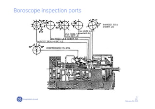
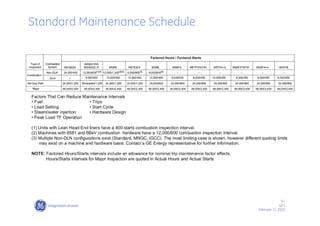
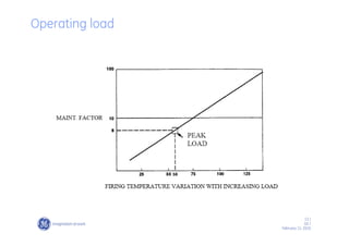
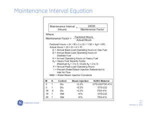
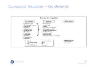
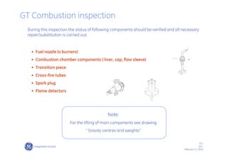
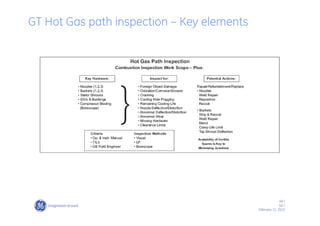
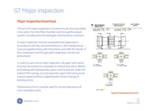
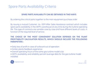
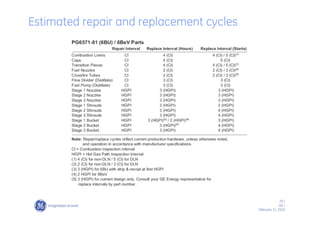
For this particular unit, the second and third-stage nozzles are FSX-414 material. The unit operates on “dry
control curve.”
At a steam injection rate of 2.4%, the value of “M” is 0.18, and “K” is 0.6.
From the hours-based criteria, the maintenance factor is determined from Figure 43.
The hours-based adjusted inspection interval is therefore,
H = 24,000/1.25
H = 19,200 hours
[Note, since total annual operating hours is 3670, the estimated time to reach
19,200 hours is 5.24 years (19,200/3670).]
[K + M(I)] x [G + 1.5(D) + Af(H) + 6(P)]
(G + D + H + P)
MF =
[0.6 + 0.18(2.4)] x [3200 + 1.5(350) + 0 + 6(120)]
(3200 + 350 + 0 + 120)
MF = = 1.25
Example – HGP Maintenance Interval Calculation
25. 25 /
GE /
February 11, 2010
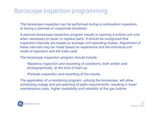
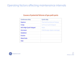
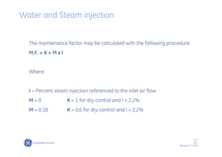
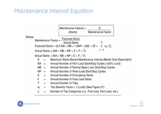
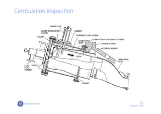
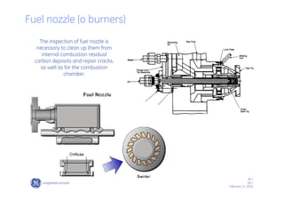
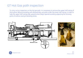
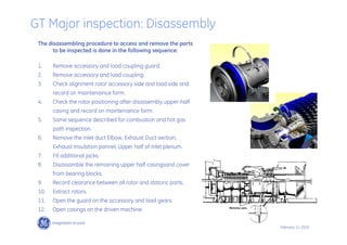
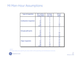
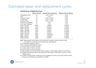
From the starts-based criteria, the maintenance factor is determined as:
The total number of part load starts/stop is NA = 40/yr
The total number of base load starts/stop is NB = 100 + 2 + 5 + 20 = 127/yr
The total number of peak load starts/stop is NP = 0/yr
The adjusted inspection interval based on starts is
S = 1200/2.0
S = 600 starts
[Note, since the total annual number of starts is 167, the estimated time to reach
600 starts is 600/167 = 3.6 years.]
In this case, the starts-based maintenance factor is greater than the hours maintenance factor and
therefore the inspection interval is set by starts. The hot gas path inspection interval is 600
starts (or 3.6 years).
0.5 (NA)+(NB)+1.3(NP)+20(E)+2(F) + (an-1)T
NA + NB + NP
MF =
0.5(40)+(127)+1.3(0)+20(2)+2(5)+(8–1)20
40+127+0
= 2
MF =
Example – HGP Maintenance Interval Calculation
26. 26 /
GE /
February 11, 2010
Gas Turbine Maintenance
Maintenance Inspections
STAND-BY INSPECTIONS
RUNNING INSPECTIONS
DISMANTLING INSPECTIONS
27. 27 /
GE /
February 11, 2010
STAND-BY INSPECTIONS
They are required when the engine is not in operation. During this period of time, the following
items should be checked :
LUBE OIL SYSTEM COMPONENTS
FUEL SYSTEM COMPONENTS
INTAKE SYSTEM AND FILTERS
INSTRUMENTATION SETTINGS AND REPAIRS/SUBSTITUTIONS
EMERGENCY BATTERIES STATUS
FLUIDS LEVELS (OILS, WATER, ETC.)
OTHER AUXILIARIES IN GENERAL
BORESCOPE INSPECTION FOR ALL THE INTERNAL PARTS
28. 28 /
GE /
February 11, 2010
RUNNING INSPECTIONS
They are required when the engine is
in operation.
During this period of time, the records
of the most important functional
parameters must be done by the
operation personnel, every one or two
hours, in order to have a good
operation trend of the system.
This will help find the root causes of
gas turbine troubles.
TYPICAL PARAMETERS
29. 29 /
GE /
February 11, 2010
DISMANTLING INSPECTIONS
Combustion System inspection
Hot Gas Path inspection
Major inspection
30. 30 /
GE /
February 11, 2010
Gas Turbine Maintenance
Combustion system inspections
33. 33 /
GE /
February 11, 2010
Combustion inspection precedure
1. Prepare turbine compartment roof for removal
2. Remove turbine compartment roof and side
panels.
3. Remove liquid fuel lines (if applicable).
4. Remove atomizing air lines (if applicable).
5. Remove gas fuel lines (if applicable).
6. Remove steam injection lines (if applicable).
7. Remove water injection lines (if applicable).
8. Remove liquid fuel check valves.
9. Remove false start drain tubing.
10. Remove fuel nozzles.
34. 34 /
GE /
February 11, 2010
11 Remove flame detectors and spark plugs.
12 Remove 11th stage cooling and sealing air
lines.
13 Unbolt and open up combustion outer casing
covers.
14 Remove crossfire tube retainers, combustion
liners, crossfire tubes and forward flow
sleeves.
15 Remove access port blank flange from upper
half turbine casing or the upper section of the
atomizing air extraction manifold.
16 Remove outer combustion casings and aft
flow sleeves.
17 Remove transition pieces.
Combustion inspection precedure
35. 35 /
GE /
February 11, 2010
• Fuel nozzle (o burners)
• Combustion chamber components ( liner, cap, flow sleeve)
• Transition piece
• Cross-fire tubes
• Spark plug
• Flame detectors
GT Combustion inspection
During this inspection the status of following components should be verified and all necessary
repair/substitution is carried out:
Note:
For the lifting of main components see drawing
“ Gravity centres and weights”
36. 36 /
GE /
February 11, 2010
The inspection of fuel nozzle is
necessary to clean up them from
internal combustion residual
carbon deposits and repair cracks,
as well as for the combustion
chamber.
Fuel nozzle (o burners)
37. 37 /
GE /
February 11, 2010
Normally, cracks inspections carried out using dye penetrating fluids sprayed on
the components surface.
Fuel nozzle (o burners)
50. 50 /
GE /
February 11, 2010
GT Hot Gas path inspection
To carry out an inspection on the hot gas path, it is necessary to remove the upper half casing of
the turbine. Before proceding with disassembly, put jacks under the lower half casing, in order to
help the upper half casing slide upward when beign opened avoiding subjecting the remaing
parts of turbine casing to bending stress.
51. 51 /
GE /
February 11, 2010
The disassembling procedure to access and remove the parts to be inspected is carried
out in the following sequence:
GT Hot Gas path inspection: Disassembly
1. Remove turbine compartment side panels. (If applicable).
2. Remove roof attachments. (If applicable)
3. Lift off turbine compartment roof. (If applicable).
4. Remove upper half cooling and sealing air piping.
5. Remove turbine casing wheel-space thermocouple wiring and
conduit.
6. Perform combustion inspection disassembly Operations.
7. Establish solid foundation and place mechanical screw jacks
under unit casings.
8. Remove upper half turbine casing.
9. Remove upper half first-stage nozzle.
10. Take turbine clearance checks.
11. Remove lower half first-stage nozzle.
12. ……
13. ……
52. 52 /
GE /
February 11, 2010
• Combustion system .
• 1st stage Nozzle.
• 1st stage shrouds.
• 2ndstage Nozzle.
• 2ndstage shrouds.
• 1st and 2nd stage turbine buckets.
• Compressor Blade (Boroscope)
GT Hot Gas path inspection
During this inspection the status of the following gas turbine section components should
be verified and all necessary repair/substitution is carried out in case of natural gas or light
distillate fuel operation:
53. 53 /
GE /
February 11, 2010
Opening Compressor and Turbine Rotor Position Checks
54. 54 /
GE /
February 11, 2010
1. Inspect first, second and third stage turbine buckets.
2. Inspect first, second and third stage bucket cover-plates.
3. Inspect the Shroud Blocks.
4. Inspect second and third stage diaphragm segments.
5. Inspection the first stage nozzles ellipticity checks.
6. Inspect combustion system components
GT Hot Gas path inspection
61. 61 /
GE /
February 11, 2010
Major inspection/overhaul
The aim of a major inspection is to examine all rotor and stator
inner parts, from the filter chamber inlet throughthe exaust
system, including also the load gear and the driven machine.
A major inspection must be scheduled and organized in
accordance with the recommendations in the maintenaince
manual supplied along with the turbine, and with the results of
the combustion and hot gas path inspections carried out
beforehand.
In order to carry out a major inspection, all upper half casing
must be removed,so as to beable to remove the rotors. Before
proceeding with disassembly, jacks must be placed under the
bottom half casings, so as to ease the upper half casing to be
moved upward without subjecting the remain casings to
bending stress.
Maintenance forms must be used for record clearances all
rotor and stator parts.
Typical maintenaince forms
GT Major inspection
62. 62 /
GE /
February 11, 2010
The disassembling procedure to access and remove the parts
to be inspected is done in the following sequence:
1. Remove accessory and load coupling guard.
2. Remove accessory and load coupling.
3. Check alignment rotor accessory side and load side and
record on maintenaince form.
4. Check the rotor positioning after disassembly upper-half
casing and record on maintenaince form.
5. Same sequence described for combustion and hot gas
path inspection.
6. Remove the Inlet duct Elbow, Exhaust Duct section,
Exhaust Insulation pannel, Upper half of Inlet plenum.
7. Fit additional jacks.
8. Disassamble the remaining upper half casingsand cover
from bearing blocks.
9. Record clearance between all rotor and statoric parts.
10. Extract rotors.
11. Open the guard on the accessory and load gears.
12. Open casings on the driven machine.
GT Major inspection: Disassembly
66. 66 /
GE /
February 11, 2010
1. Inspect No. 1, 2 journal bearings and seals.
2. Inspect No. 1 thrust bearings and seals.
3. Clean, inspect compressor rotor, stator blade, inlet guide vanes and
compressor and turbine casings.
4. Inspect first, second and third-stage turbine buckets and wheel
dovetails.
5. Inspect first, second and third-stage shrouds and diaphragm seals.
6. Perform Hot Gas Path Inspection
GT Major inspection: Inspection
67. 67 /
GE /
February 11, 2010
Components acceptability criteria
More example components acceptability criteria
68. 68 /
GE /
February 11, 2010
Load gear site
alignment fixture
Turbine site
Attach the alignment fixture and dial indicators to the
turbine shaft and check the turbine to load gear alignment.
Refer to the Instructions and Data Alignment-Field, in the
Reference Drawings Section of the service manual for
alignment specifications.
Gas Turbine on-site Alignment
69. 69 /
GE /
February 11, 2010
CHECKS TO BE DONE BEFORE
RESTARTING THE TURBINE
WARNING
TAKE CARE THAT NO FOREIGN
OBJECTS (TOOLS OR OTHER
HARDWARE) ARE FORGOTTEN
INSIDE TURBINE.
OTHER CHECKS ARE LISTED IN THE
SERVICE MANUAL SECT. 2
Gas Turbine Maintenance
70. 70 /
GE /
February 11, 2010
The determination of the manpower and the relevant times required to carry
out the three levels of inspections depend on the following assumptions :
• Intervention with or without the assistance of the OEM
supervision
• Critical spares availability at the plant site
• Repair times in parallel to the substitution activities
• All the necessary standard and OEM’s recommended special
tooling available
• Skill of personnel
• Scheduled inspection
Manpower planning and type
71. 71 /
GE /
February 11, 2010
To obtain successful maintenance planning and operating economical
results it is very important to consider the gas turbine system tear-
down time required to accomplish all the maintenance actions.
Due to the above, a good spare parts planning will reduce the waiting
time from disassembly to reassembly sequence period, during which
the plant is out of operation.
Spare Parts planning
72. 72 /
GE /
February 11, 2010
SPARE PARTS
RECOMMEND
ED FOR
INSPECTIONS
Spare Parts planning
73. 73 /
GE /
February 11, 2010
SPARE PARTS AVAILABILITY CAN BE OBTAINED IN TWO WAYS
By ordering the critical parts together to the main equipment purchase order
By issuing a mutual Customer -to- OEM After Sales Assistance contract which includes
spare parts availability in the OEM’s warehouse at any time during the turbine operating
life. This type of contracts are variable case by case and have different levels of costs, in
function of the required level of service.
THE CHOICE OF THE MOST CONVENIENT SOLUTION DEPENDS ON THE PLANT
PROFITABILITY CALCULATION RESULTS, WHICH SHOULD INCLUDE THE FOLLOWING
PARAMETERS :
• Daily loss of profit in case of turbounit out of operation
• Similar plants feedback experience
• Overall operating hours of the same gas turbine model club
• OEM’s availability and reliability percent average data for the gas turbine model
installed
Spare Parts Availability Criteria
74. 74 /
GE /
February 11, 2010
Type of inspection Ref. turbine
rating (MW)
Average
crew size
8 hour
shifts
2 2 2
5 2 2
Combustion inspection 10 2 2
20 4 5
40 5 10
>100 6 13
2 2 7
5 2 7
Hot gas path parts 10 2 7
20 6 10
40 9 15
>100 10 30
2 4 10
5 4 14
Major inspection 10 4 15
20 8 20
40 10 35
>100 11 50
NOTE
Average values. For specific job values refer to the operating and maintenance manuals.
MI Man-Hour Assumptions
75. 75 /
GE /
February 11, 2010
Availability and reliability data are very important for both gas turbine model
selection and maintenance.
These two factors are used to quantify the ratio between not scheduled gas
turbine “out of service” times and the potential operating time/year of the
gas turbine.
There are many different (but similar) formulas to calculate the above percent
values
Availability and Reliability Concepts
76. 76 /
GE /
February 11, 2010
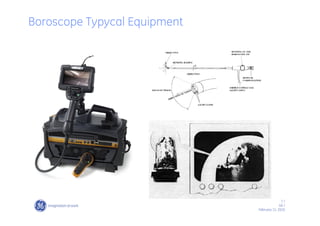
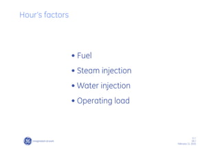
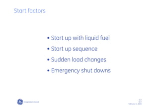
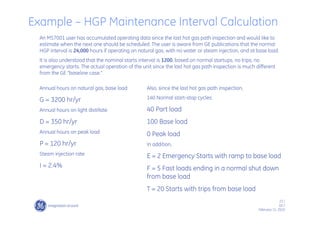
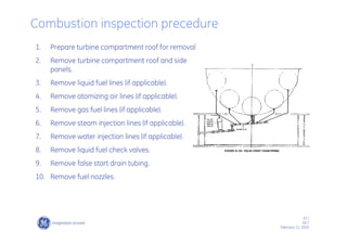
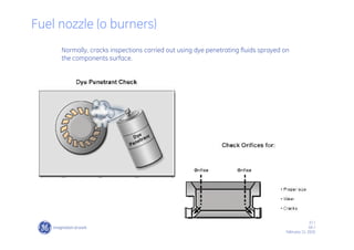
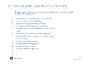
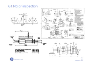
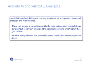
Availability is defined as “the probability of being available, independent of whether or not
the unit is needed”.
Reliability = 100 x [ PH - FOH] / PH [ % ]
Reliability is defined as “the probability of not being forced out of service when the unit is
needed”.
PH = Sum of the annual operating hours, standby (ready to start) hours, not
operating hours due to external causes.
FOH = Forced Outage Hours. Period of time during which the maintenance team
is actually working during forced outage.
POH = Planned Outage Hours. Period of time during which the maintenance team
is actually working during planned outage.
Availability = 100 x [ PH - (FOH+POH)] / PH [ % ]
Availability and Reliability Concepts