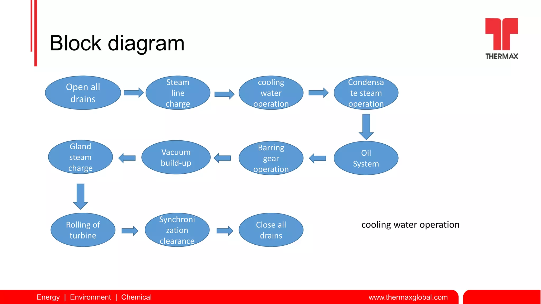
Energy | Environment | Chemical www.thermaxglobal.com
Presented by –:
Mr. Akshay kunakekar
shift- incharge
Energy | Environment | Chemical www.thermaxglobal.com
Introduction
Operation of steam turbine is a complex process. Before starting the rolling of a
turbine, auxiliary systems, are to be properly put in service. Special care is required
to be taken for starting of Turbine.
Normally for start up of a turbine some sequence of operation is
followed. We will discuss the operation of different systems as per sequence.
NOTE-:
Don’t do any field activities without informing to control room
Energy | Environment | Chemical www.thermaxglobal.com
Block diagram
Open all
drains
Steam
line
charge
cooling
water
operation
Condensa
te steam
operation
Oil
System
Barring
gear
operation
Vacuum
build-up
Gland
steam
charge
Rolling of
turbine
Synchroni
zation
clearance
Close all
drains
cooling water operation
Energy | Environment | Chemical www.thermaxglobal.com
Operation of steam line charge.
1. First of all drains are should be in open condition before start the steam line charging.
2. Open the warm up went to charge the Turbine inlet steam line as per OEM suggested
parameters.
3. Give clearance to control room for open the MSSV Bypass .
4. Throttle the steam line drain after removing of condensate.
5. After steam line in operation close the main drain and traps to be taken in line.
Energy | Environment | Chemical www.thermaxglobal.com
Before Steam Charging
Following Drains should be in open condition.
1. Main steam line drain.
2. Warm-up vent open.
3. Throttle valve drain.
4. ESV drain.
5. Casing drain.
6. Wheel case drain.
7. Extraction line drain.
8. PRDS line drain.
Energy | Environment | Chemical www.thermaxglobal.com
Casing drain ESV Drain
Energy | Environment | Chemical www.thermaxglobal.com
QCNRV before & after drain Wheel chamber drain
Energy | Environment | Chemical www.thermaxglobal.com
Throttle valve drain. Main steam line drain.
Energy | Environment | Chemical www.thermaxglobal.com
Operation of cooling water system
To circulate cooling water in the condenser, cooling water pumps are to be started.
Following steps are followed to circulate cooling water in the condenser.
1. Ensure level of the cooling tower basin is normal.
2. Keep suction valve of the pump in open condition and discharge valve in closed
condition.
3 Ensure inlet and outlet cooling water valves of condenser and hot water distributor
valves of cooling tower are in open condition.
4. Do the priming & Start the pump. If there is variable speed drive then start the pump
at lower speed and gradually increase the speed.
5. Open the discharge valve.
6. Observe cooling water is falling on the cooling tower.
7. Increase speed or Start other pump to get required amount of cooling water flow at
the condenser. –
8.Observe all the cooling water pumps are sharing load.
Energy | Environment | Chemical www.thermaxglobal.com
Inlet and outlet cooling water valves
of condenser
level of the cooling tower basin
Energy | Environment | Chemical www.thermaxglobal.com
Condensate steam operation
1.Ensure condenser hot well level is adequate. Otherwise maintain the hot well with
make up DM water.
2. Open suction of the pump. Start the pump. Open discharge valve and Ensure
Differential pressure of the strainer is normal.
3. Open condensate inlet and outlet valves of GVC, ejector condenser.
Energy | Environment | Chemical www.thermaxglobal.com
Condensate extraction pump
Energy | Environment | Chemical www.thermaxglobal.com
Operation of oil system
1. Ensure the all work permit is closed.
2. Ensure Proper supply is available
3. Ensure emergency push button is release from field.
4. Ensure Main oil tank level is normal.
5. Valves provided at oil line at oil filter and oil cooler are in open condition.
6. Cooling water outlet valve of oil cooler is in close condition .
7. Start oil pump.
8. Check oil filter differential pressure. If it is high, change the filter cartridge or change the
filter.
9. Maintain oil temperature by adjusting cooling water outlet valve of oil cooler.
10. Keep the standby oil pump and Emergency oil pump in Auto mode.
11. Ensure overhead tank is full.
Energy | Environment | Chemical www.thermaxglobal.com
Oil system
Energy | Environment | Chemical www.thermaxglobal.com
Overhead tank overflow indication EOP mode selection
Energy | Environment | Chemical www.thermaxglobal.com
Operation of barring gear
Before rolling, turbine is required to be kept on barring operation at least 8
hours before. To put the turbine on barring operation.
1. Ensure lube oil system(AOP PUMP) is in service and oil is circulating at
all the bearings and oil pressure is at desired level.i.e.1.8-2kg/cm2.
2. Ensure emergency release button from local.
3. Start barring gear motor.
4. Observe rotor is rotating at barring speed without increase in bearing
vibration and temperature and there is no abnormal sound.
NOTE-:
when DC supply failed then Put BGM in manual mode and local
emergency push button of BGM should be pushed.
Energy | Environment | Chemical www.thermaxglobal.com
Vacuum build up
Ejector/
hogger
Vacuum
pump
Energy | Environment | Chemical www.thermaxglobal.com
Vacuum build up
1.Ensure auxiliary steam at desired pressure and temperature is available.
2. Ensure the vacuum break valve of the condenser is closed.
3. Ensure cooling water is circulating in the condenser and turbine gland is charged
fully.
4. Open steam valve of the hogger.
5. Observe steam is vented to atmosphere.
6. Open hogger air valve.
7. Observe vacuum inside condenser is increasing slowly
8. After normalization of plant take ejector in line.
Energy | Environment | Chemical www.thermaxglobal.com
Ejector & Hogger system
Steam valve Air valve
Energy | Environment | Chemical www.thermaxglobal.com
vacuum pump
Energy | Environment | Chemical www.thermaxglobal.com
Operation of gland steam charging
1.ensure auxiliary steam is available from PRDS at desired pressure and
temperature i.e. 10 kg /cm2 & 250 deg.c
2. Ensure GVC is in running condition.
3.Open gland steam header and gland drains.
4.Open HP side valve slowly. (1)
5.Open LP side valve slowly.(2)
1 2
Energy | Environment | Chemical www.thermaxglobal.com
Rolling of turbine
1. Ensure lube oil and control oil is available, cooling water is flowing in
condenser, turbine is on barring, gland is properly charged and vacuum is
available.
2. Steam pressure and temperature are within limit.
3. All the turbine tripping interlocks are healthy.
4. .Ensure ESV is in closed position .
5. Acknowledge the Alarm on DCS as well TCP
6. Alarm rest on DCS as well TCP
7. Turbine Trip reset
8. LP reset. On DCS if not reset do on field.
9. SOV reset from panel.
10. ESV open command.
11. Woodward 505 press “RESET” button.
12. Woodward 505 press “RUN” button.
13. observe bearing temperature, lube oil pressure at bearings, bearing
vibration, any abnormal sound during start-up.
Energy | Environment | Chemical www.thermaxglobal.com
14. Ensure barring device is disengaged.
15.Maintain lube oil temperature by adjusting cooling water at oil cooler.
16. At critical speed zone the speed to be raised faster and bearing vibrations should
be within limit.
17. Once turbine reaches full speed check all the parameters.
18.if the main oil pump is mechanically coupled with turbine rotor then stop AOP and
check oil pressure.
19. Give clearance to electrical dept. for synchronization.
20. After taking load on TG close the warm up went & all drains of turbine
Energy | Environment | Chemical www.thermaxglobal.com
Turbine Alarm Rest page
Energy | Environment | Chemical www.thermaxglobal.com
LP Reset
Energy | Environment | Chemical www.thermaxglobal.com
SOV Reset ESV Open command
Energy | Environment | Chemical www.thermaxglobal.com
Woodward 505
Energy | Environment | Chemical www.thermaxglobal.com
Thank you ……

Final Turbine rolling ppt Akshay.pptx

  • 1.
    Energy | Environment| Chemical www.thermaxglobal.com Presented by –: Mr. Akshay kunakekar shift- incharge
  • 2.
    Energy | Environment| Chemical www.thermaxglobal.com Introduction Operation of steam turbine is a complex process. Before starting the rolling of a turbine, auxiliary systems, are to be properly put in service. Special care is required to be taken for starting of Turbine. Normally for start up of a turbine some sequence of operation is followed. We will discuss the operation of different systems as per sequence. NOTE-: Don’t do any field activities without informing to control room
  • 3.
    Energy | Environment| Chemical www.thermaxglobal.com Block diagram Open all drains Steam line charge cooling water operation Condensa te steam operation Oil System Barring gear operation Vacuum build-up Gland steam charge Rolling of turbine Synchroni zation clearance Close all drains cooling water operation
  • 4.
    Energy | Environment| Chemical www.thermaxglobal.com
  • 5.
    Energy | Environment| Chemical www.thermaxglobal.com Operation of steam line charge. 1. First of all drains are should be in open condition before start the steam line charging. 2. Open the warm up went to charge the Turbine inlet steam line as per OEM suggested parameters. 3. Give clearance to control room for open the MSSV Bypass . 4. Throttle the steam line drain after removing of condensate. 5. After steam line in operation close the main drain and traps to be taken in line.
  • 6.
    Energy | Environment| Chemical www.thermaxglobal.com Before Steam Charging Following Drains should be in open condition. 1. Main steam line drain. 2. Warm-up vent open. 3. Throttle valve drain. 4. ESV drain. 5. Casing drain. 6. Wheel case drain. 7. Extraction line drain. 8. PRDS line drain.
  • 7.
    Energy | Environment| Chemical www.thermaxglobal.com Casing drain ESV Drain
  • 8.
    Energy | Environment| Chemical www.thermaxglobal.com QCNRV before & after drain Wheel chamber drain
  • 9.
    Energy | Environment| Chemical www.thermaxglobal.com Throttle valve drain. Main steam line drain.
  • 10.
    Energy | Environment| Chemical www.thermaxglobal.com Operation of cooling water system To circulate cooling water in the condenser, cooling water pumps are to be started. Following steps are followed to circulate cooling water in the condenser. 1. Ensure level of the cooling tower basin is normal. 2. Keep suction valve of the pump in open condition and discharge valve in closed condition. 3 Ensure inlet and outlet cooling water valves of condenser and hot water distributor valves of cooling tower are in open condition. 4. Do the priming & Start the pump. If there is variable speed drive then start the pump at lower speed and gradually increase the speed. 5. Open the discharge valve. 6. Observe cooling water is falling on the cooling tower. 7. Increase speed or Start other pump to get required amount of cooling water flow at the condenser. – 8.Observe all the cooling water pumps are sharing load.
  • 11.
    Energy | Environment| Chemical www.thermaxglobal.com Inlet and outlet cooling water valves of condenser level of the cooling tower basin
  • 12.
    Energy | Environment| Chemical www.thermaxglobal.com Condensate steam operation 1.Ensure condenser hot well level is adequate. Otherwise maintain the hot well with make up DM water. 2. Open suction of the pump. Start the pump. Open discharge valve and Ensure Differential pressure of the strainer is normal. 3. Open condensate inlet and outlet valves of GVC, ejector condenser.
  • 13.
    Energy | Environment| Chemical www.thermaxglobal.com Condensate extraction pump
  • 14.
    Energy | Environment| Chemical www.thermaxglobal.com Operation of oil system 1. Ensure the all work permit is closed. 2. Ensure Proper supply is available 3. Ensure emergency push button is release from field. 4. Ensure Main oil tank level is normal. 5. Valves provided at oil line at oil filter and oil cooler are in open condition. 6. Cooling water outlet valve of oil cooler is in close condition . 7. Start oil pump. 8. Check oil filter differential pressure. If it is high, change the filter cartridge or change the filter. 9. Maintain oil temperature by adjusting cooling water outlet valve of oil cooler. 10. Keep the standby oil pump and Emergency oil pump in Auto mode. 11. Ensure overhead tank is full.
  • 15.
    Energy | Environment| Chemical www.thermaxglobal.com Oil system
  • 16.
    Energy | Environment| Chemical www.thermaxglobal.com Overhead tank overflow indication EOP mode selection
  • 17.
    Energy | Environment| Chemical www.thermaxglobal.com Operation of barring gear Before rolling, turbine is required to be kept on barring operation at least 8 hours before. To put the turbine on barring operation. 1. Ensure lube oil system(AOP PUMP) is in service and oil is circulating at all the bearings and oil pressure is at desired level.i.e.1.8-2kg/cm2. 2. Ensure emergency release button from local. 3. Start barring gear motor. 4. Observe rotor is rotating at barring speed without increase in bearing vibration and temperature and there is no abnormal sound. NOTE-: when DC supply failed then Put BGM in manual mode and local emergency push button of BGM should be pushed.
  • 18.
    Energy | Environment| Chemical www.thermaxglobal.com Vacuum build up Ejector/ hogger Vacuum pump
  • 19.
    Energy | Environment| Chemical www.thermaxglobal.com Vacuum build up 1.Ensure auxiliary steam at desired pressure and temperature is available. 2. Ensure the vacuum break valve of the condenser is closed. 3. Ensure cooling water is circulating in the condenser and turbine gland is charged fully. 4. Open steam valve of the hogger. 5. Observe steam is vented to atmosphere. 6. Open hogger air valve. 7. Observe vacuum inside condenser is increasing slowly 8. After normalization of plant take ejector in line.
  • 20.
    Energy | Environment| Chemical www.thermaxglobal.com Ejector & Hogger system Steam valve Air valve
  • 21.
    Energy | Environment| Chemical www.thermaxglobal.com vacuum pump
  • 22.
    Energy | Environment| Chemical www.thermaxglobal.com Operation of gland steam charging 1.ensure auxiliary steam is available from PRDS at desired pressure and temperature i.e. 10 kg /cm2 & 250 deg.c 2. Ensure GVC is in running condition. 3.Open gland steam header and gland drains. 4.Open HP side valve slowly. (1) 5.Open LP side valve slowly.(2) 1 2
  • 23.
    Energy | Environment| Chemical www.thermaxglobal.com Rolling of turbine 1. Ensure lube oil and control oil is available, cooling water is flowing in condenser, turbine is on barring, gland is properly charged and vacuum is available. 2. Steam pressure and temperature are within limit. 3. All the turbine tripping interlocks are healthy. 4. .Ensure ESV is in closed position . 5. Acknowledge the Alarm on DCS as well TCP 6. Alarm rest on DCS as well TCP 7. Turbine Trip reset 8. LP reset. On DCS if not reset do on field. 9. SOV reset from panel. 10. ESV open command. 11. Woodward 505 press “RESET” button. 12. Woodward 505 press “RUN” button. 13. observe bearing temperature, lube oil pressure at bearings, bearing vibration, any abnormal sound during start-up.
  • 24.
    Energy | Environment| Chemical www.thermaxglobal.com 14. Ensure barring device is disengaged. 15.Maintain lube oil temperature by adjusting cooling water at oil cooler. 16. At critical speed zone the speed to be raised faster and bearing vibrations should be within limit. 17. Once turbine reaches full speed check all the parameters. 18.if the main oil pump is mechanically coupled with turbine rotor then stop AOP and check oil pressure. 19. Give clearance to electrical dept. for synchronization. 20. After taking load on TG close the warm up went & all drains of turbine
  • 25.
    Energy | Environment| Chemical www.thermaxglobal.com Turbine Alarm Rest page
  • 26.
    Energy | Environment| Chemical www.thermaxglobal.com LP Reset
  • 27.
    Energy | Environment| Chemical www.thermaxglobal.com SOV Reset ESV Open command
  • 28.
    Energy | Environment| Chemical www.thermaxglobal.com Woodward 505
  • 29.
    Energy | Environment| Chemical www.thermaxglobal.com Thank you ……