Downloaded 431 times


![113
[ Custom Home ]!](https://image.slidesharecdn.com/introtovrf2-160817052338/85/Introduction-to-VRF-113-320.jpg)


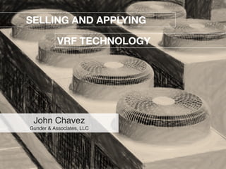
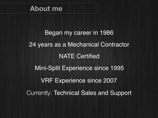
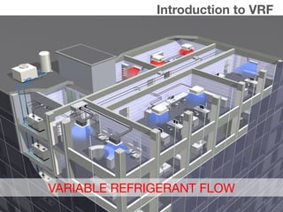
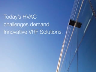
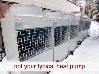
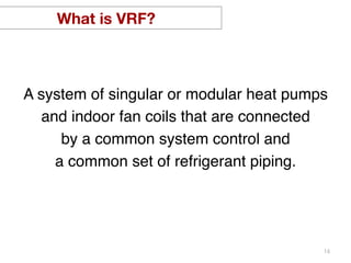
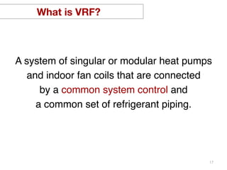
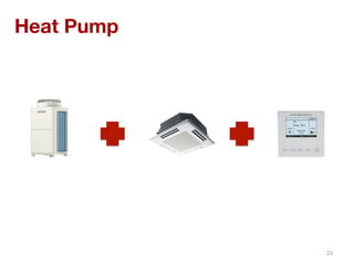
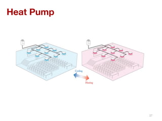
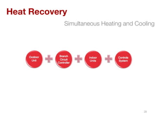
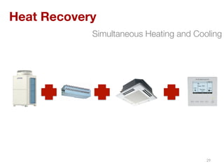
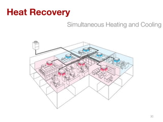
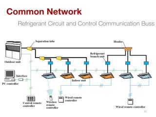
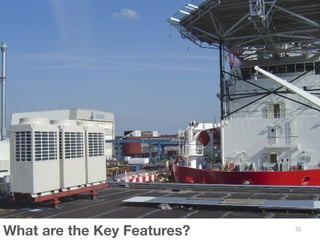
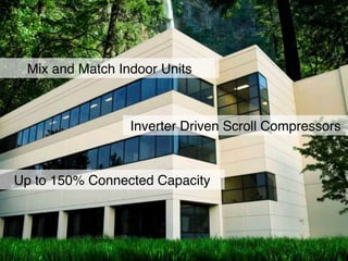
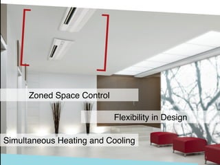
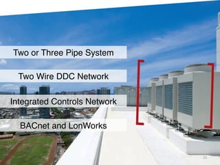
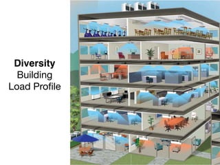
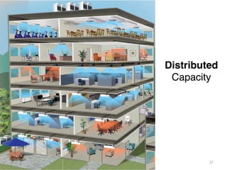
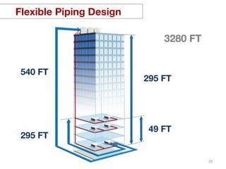
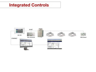
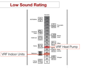
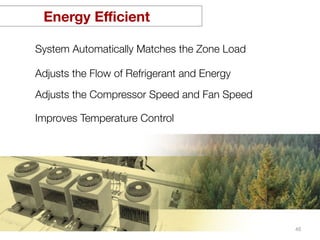
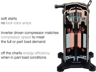
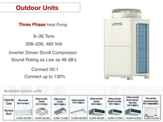
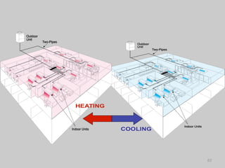
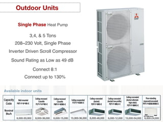
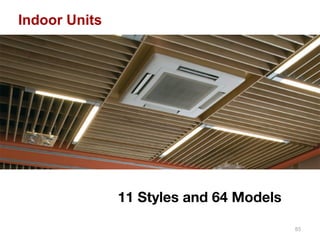
The document provides an overview of Variable Refrigerant Flow (VRF) technology, highlighting its components, features, and applications in HVAC systems. John Chavez, a mechanical contractor with extensive experience, discusses the efficiency and design flexibility of VRF systems compared to traditional HVAC solutions. It emphasizes benefits such as energy efficiency, personalized control, and reduced maintenance requirements.