Downloaded 235 times
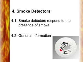
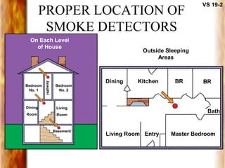
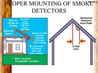
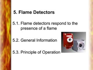
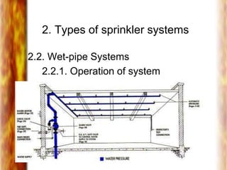
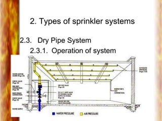
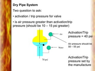
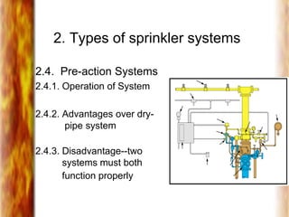
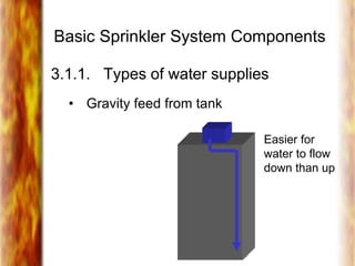
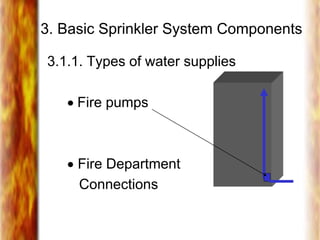
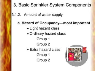
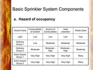
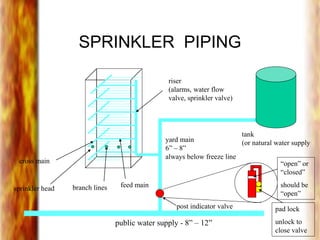
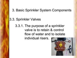
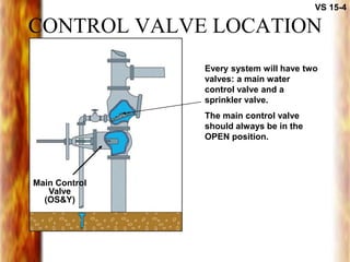
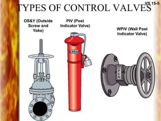
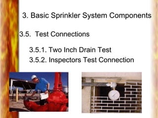
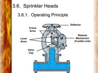
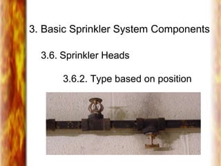
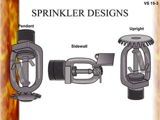
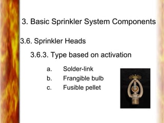
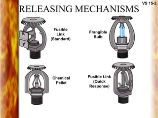
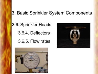

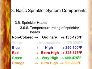
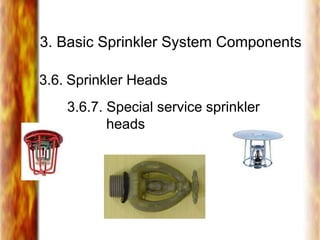
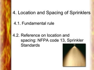
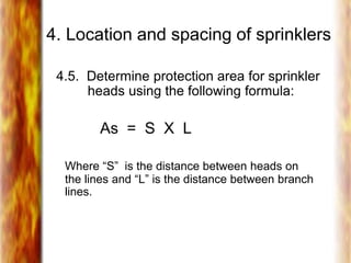
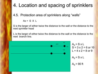
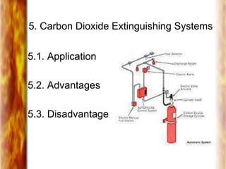


This document discusses fire detection and alarm systems as well as fixed fire suppression systems. It covers various types of fire detectors including heat, smoke, and flame detectors. It also describes different types of sprinkler systems such as wet-pipe, dry-pipe, pre-action, and deluge systems. Key components of sprinkler systems like water supplies, piping, valves, alarms and sprinkler heads are explained. Placement and spacing of sprinklers depends on occupancy hazard classification. Other fixed suppression systems like carbon dioxide, dry chemical, and foam systems are also outlined.


