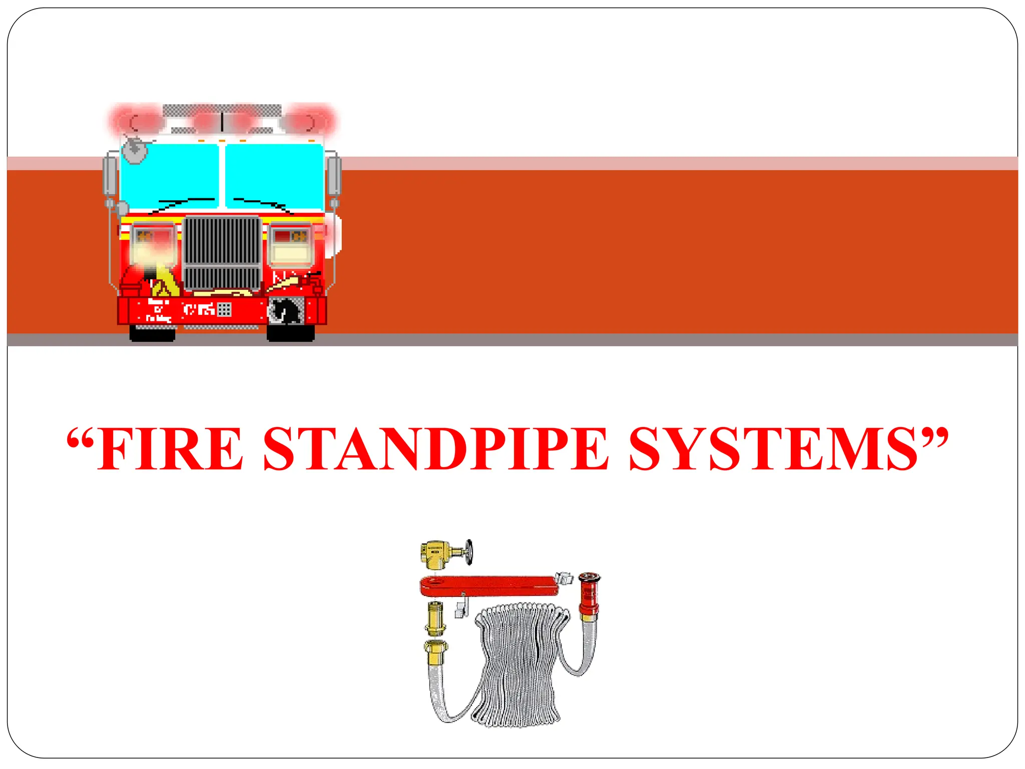
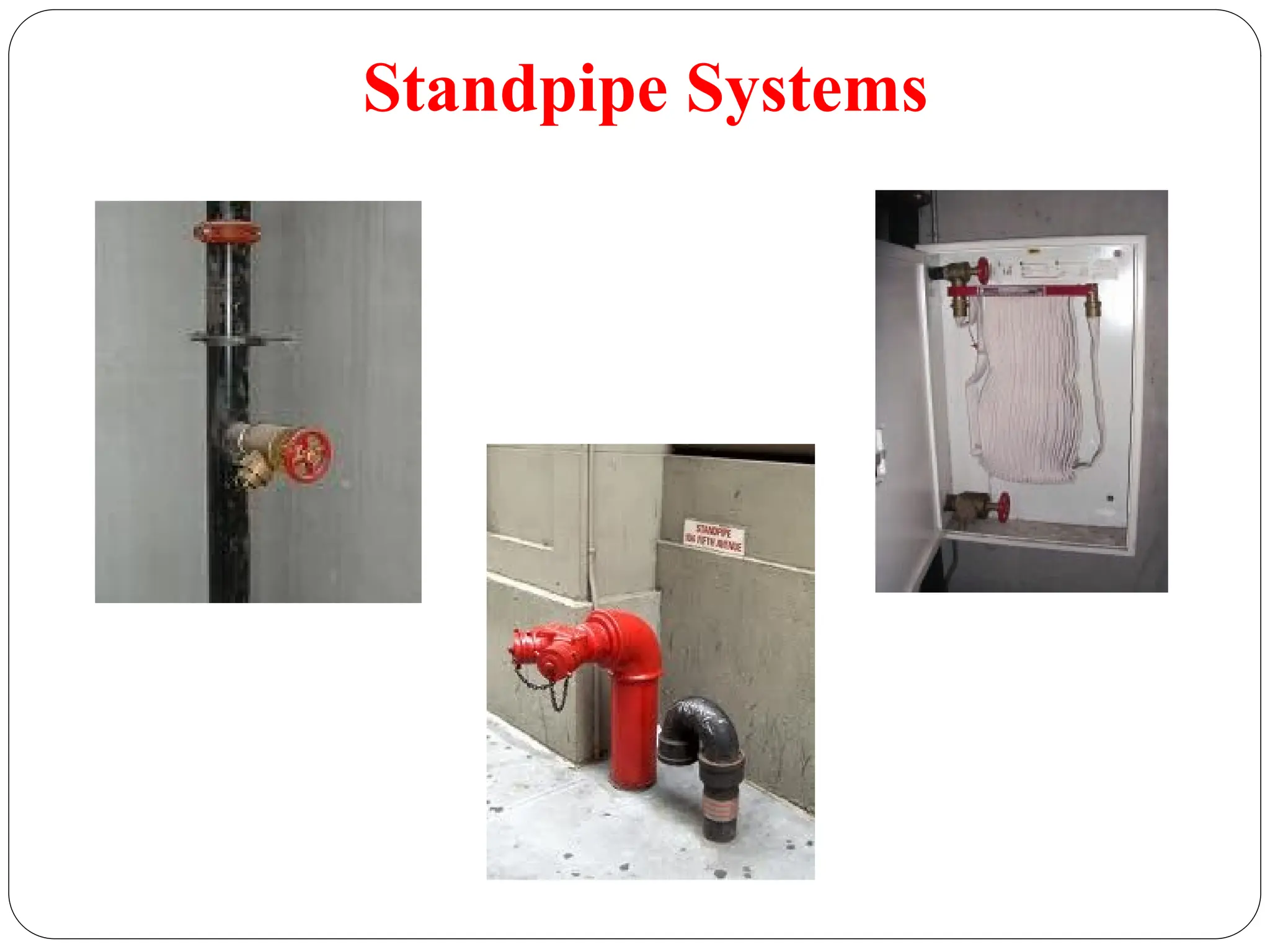
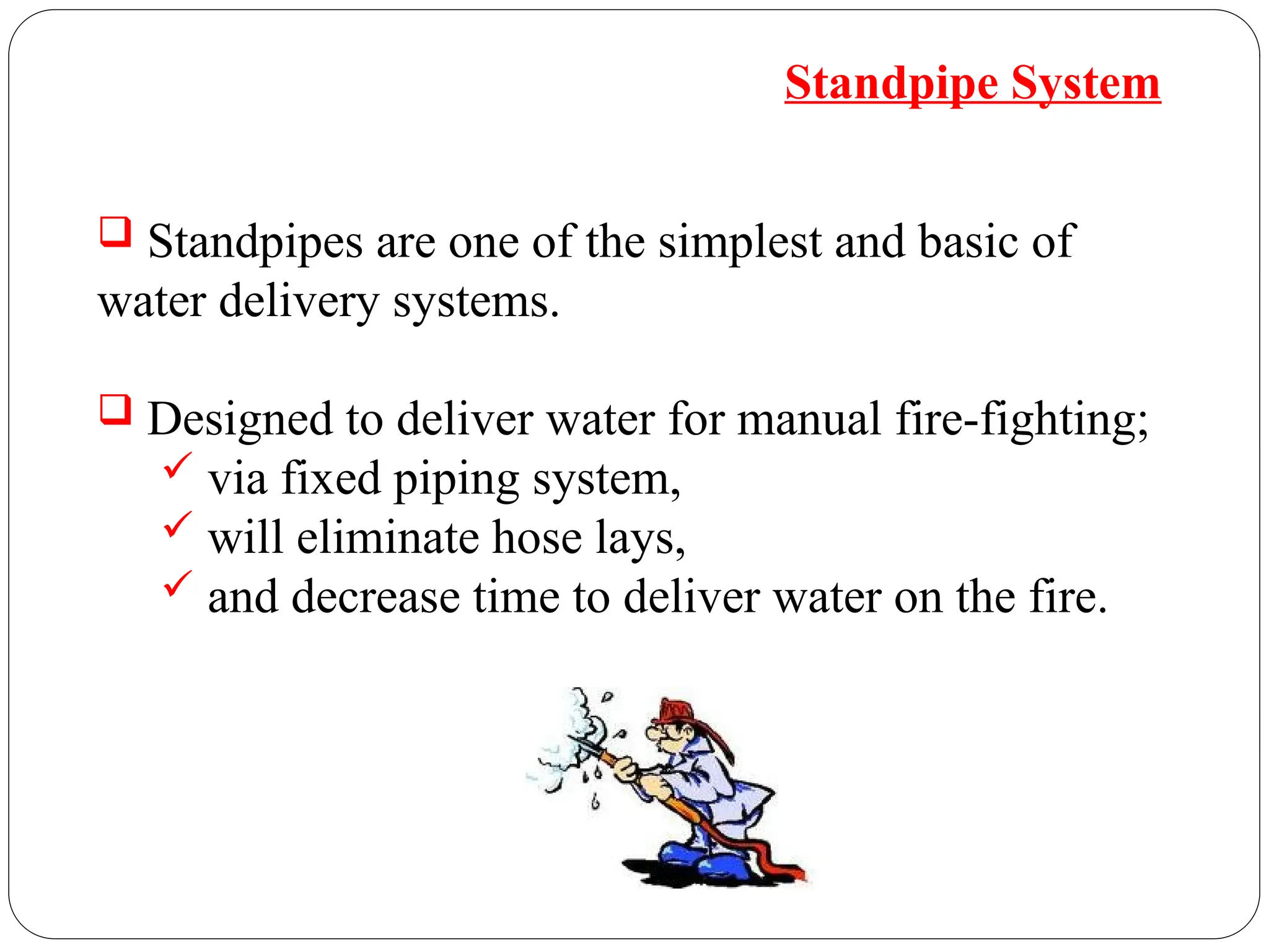
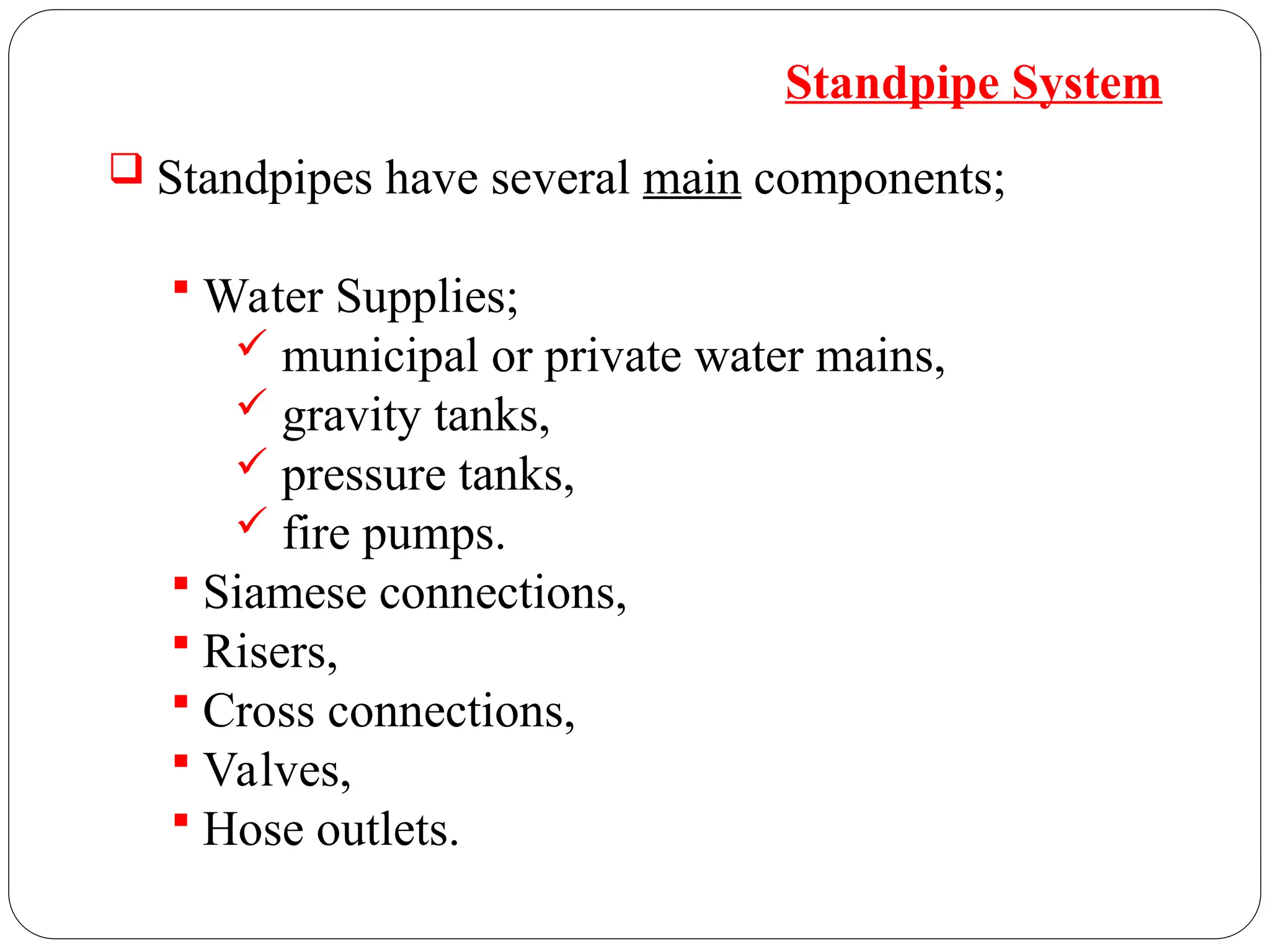
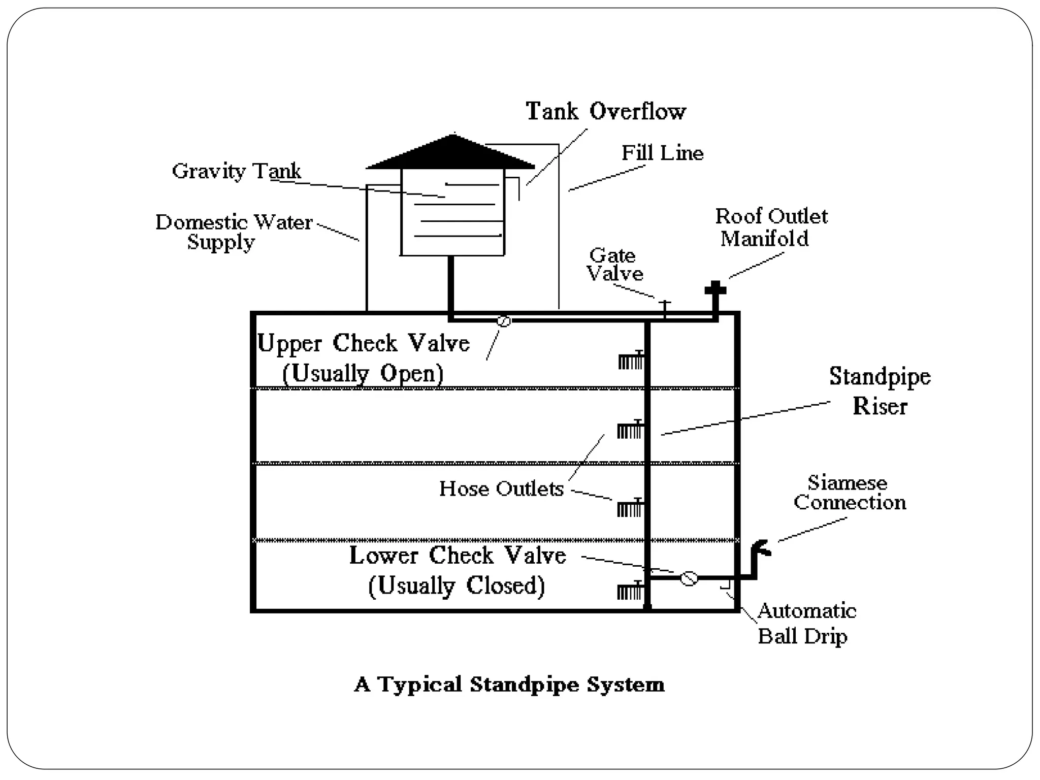
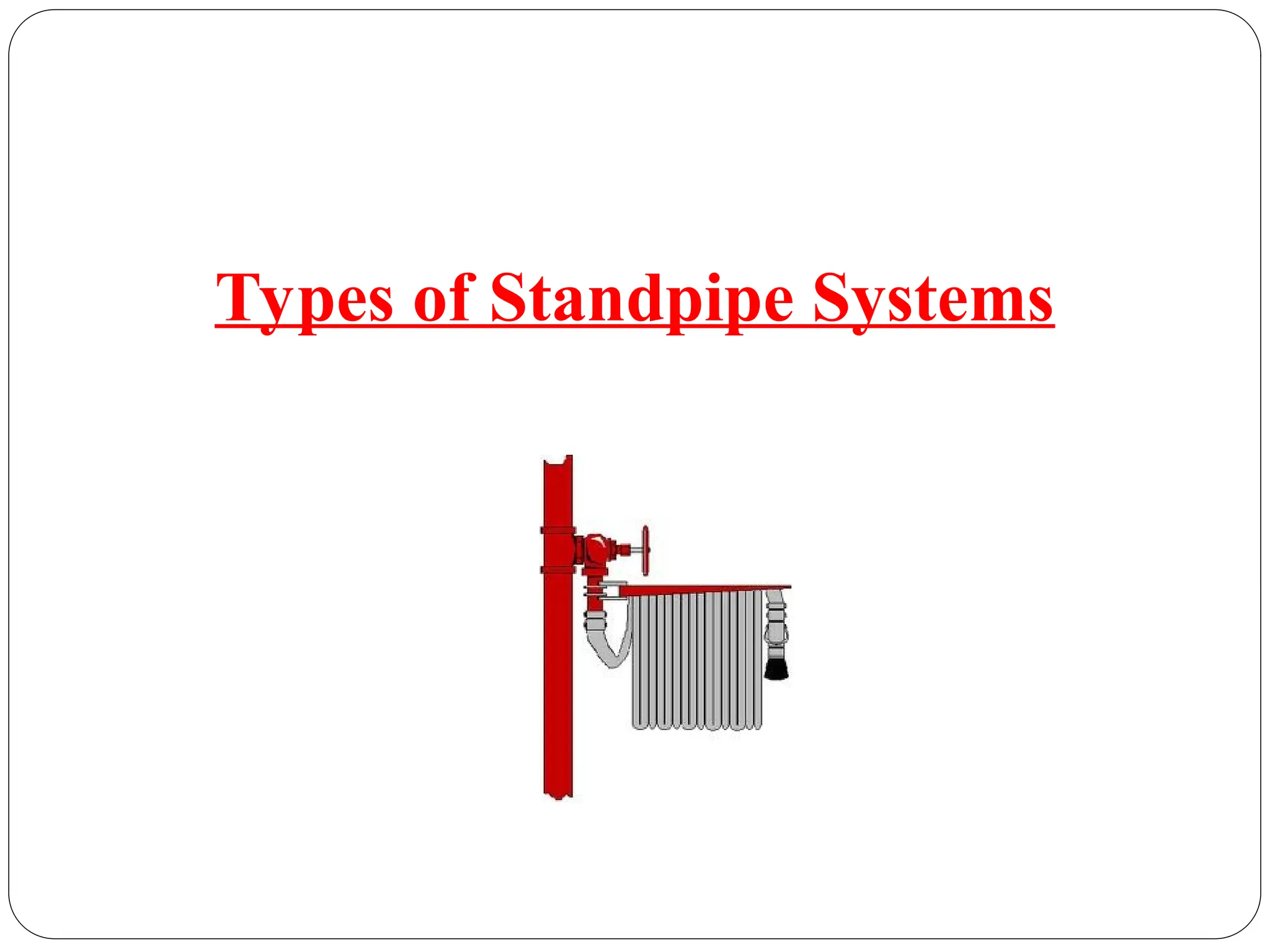
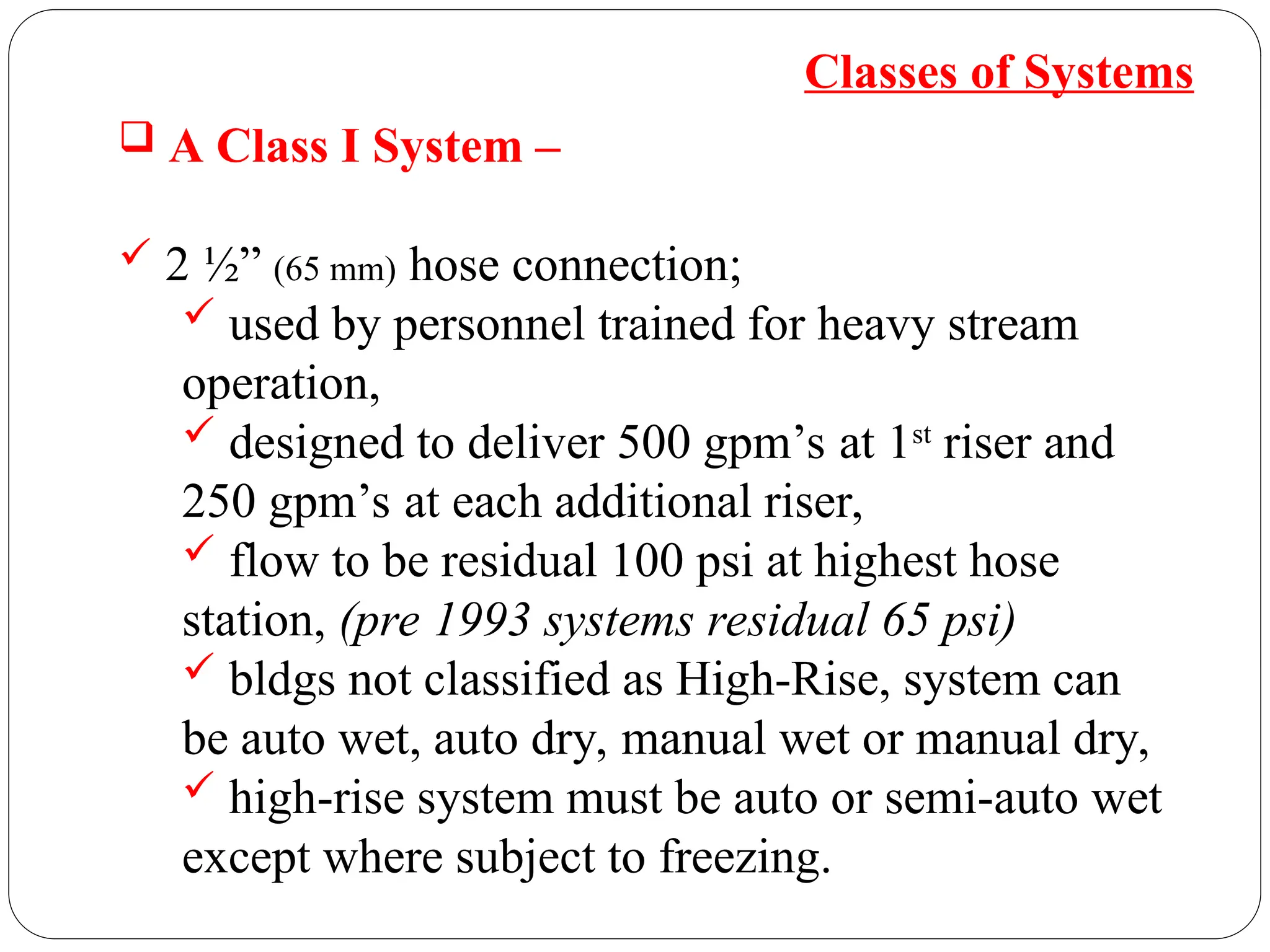
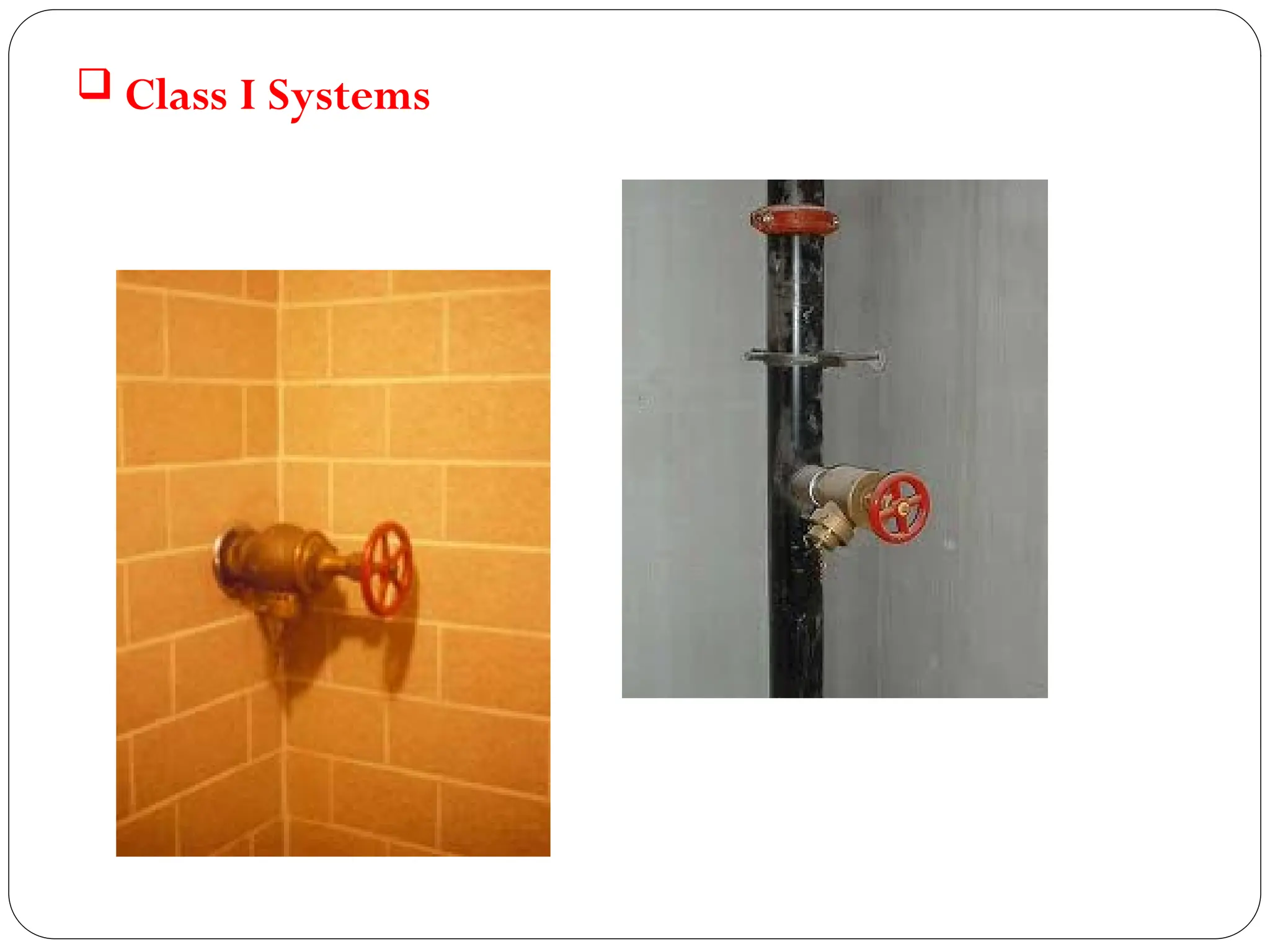
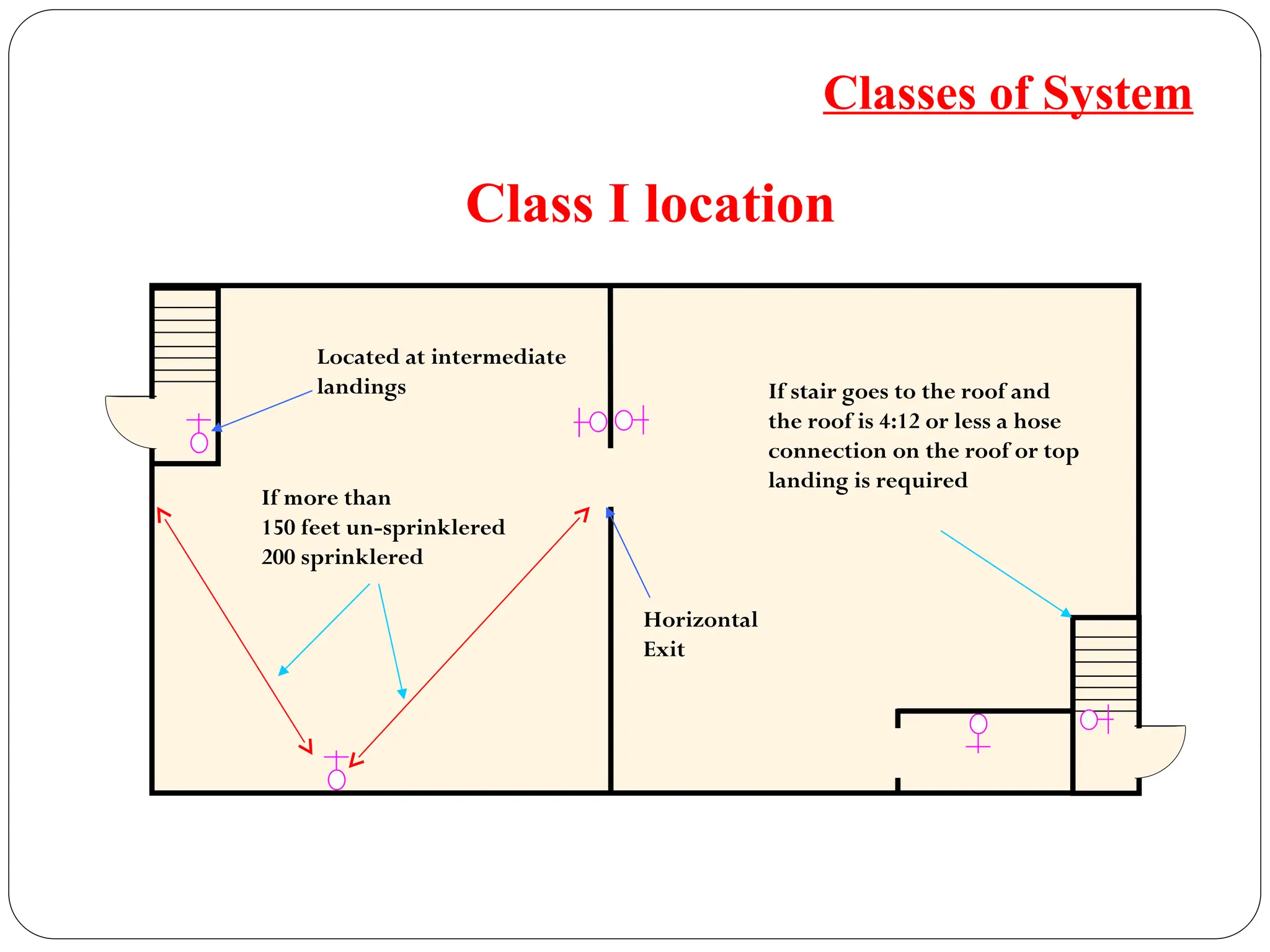
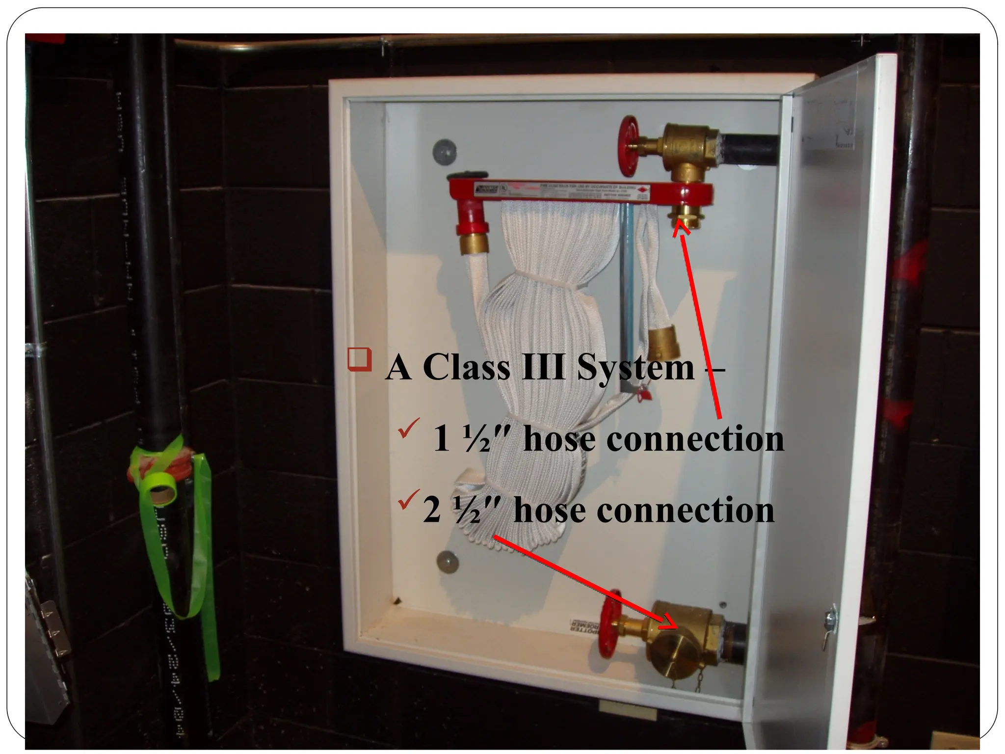
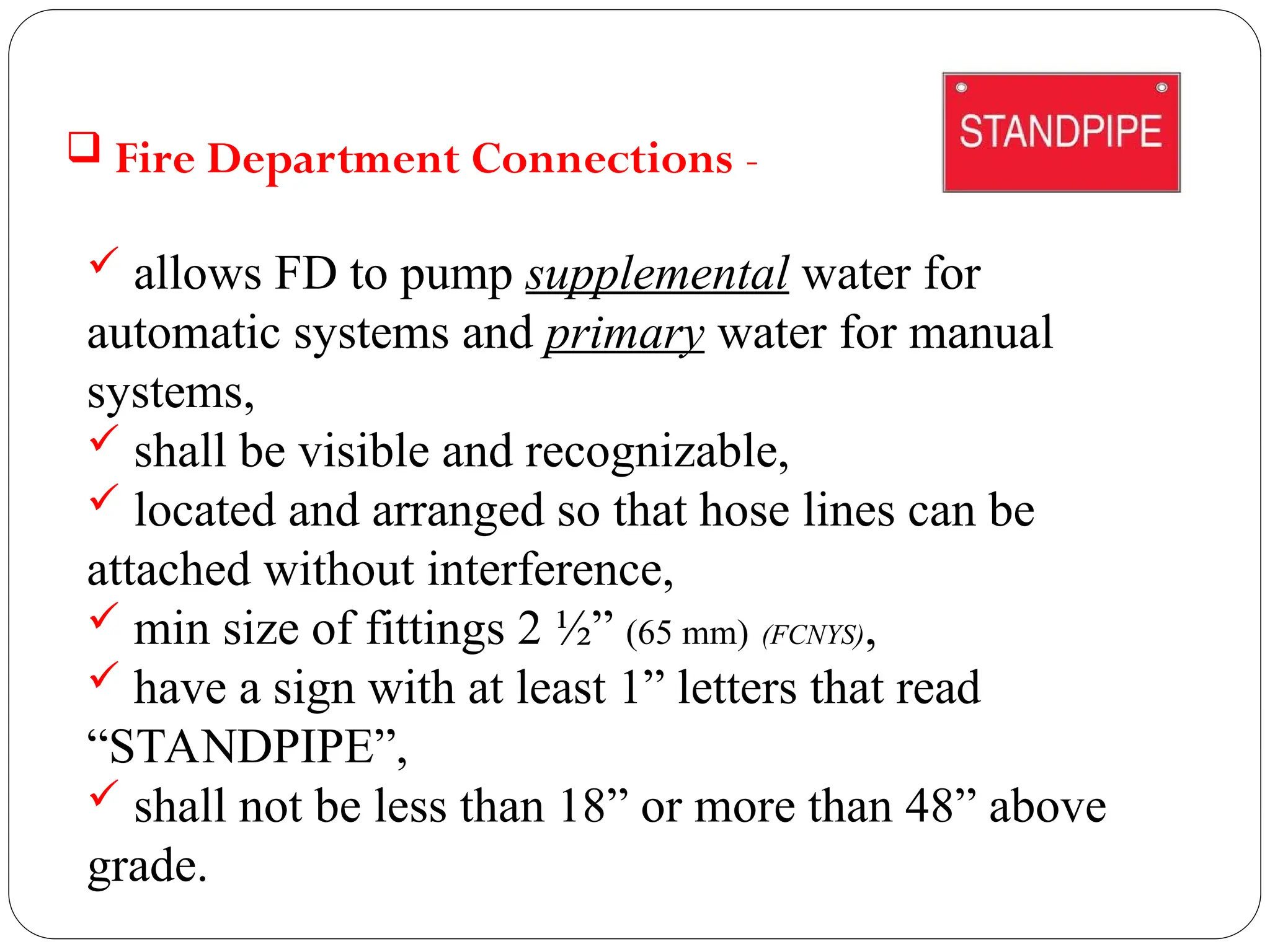
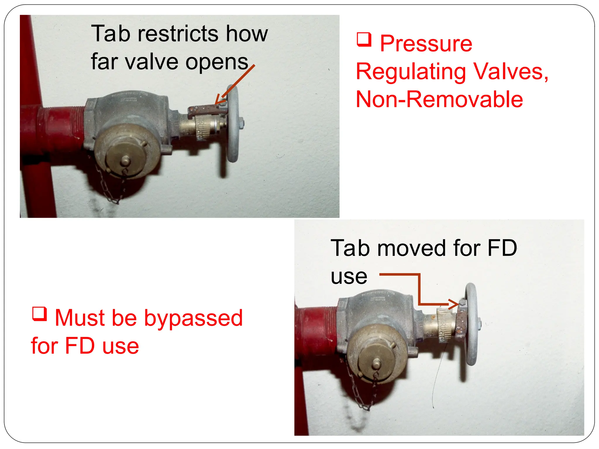
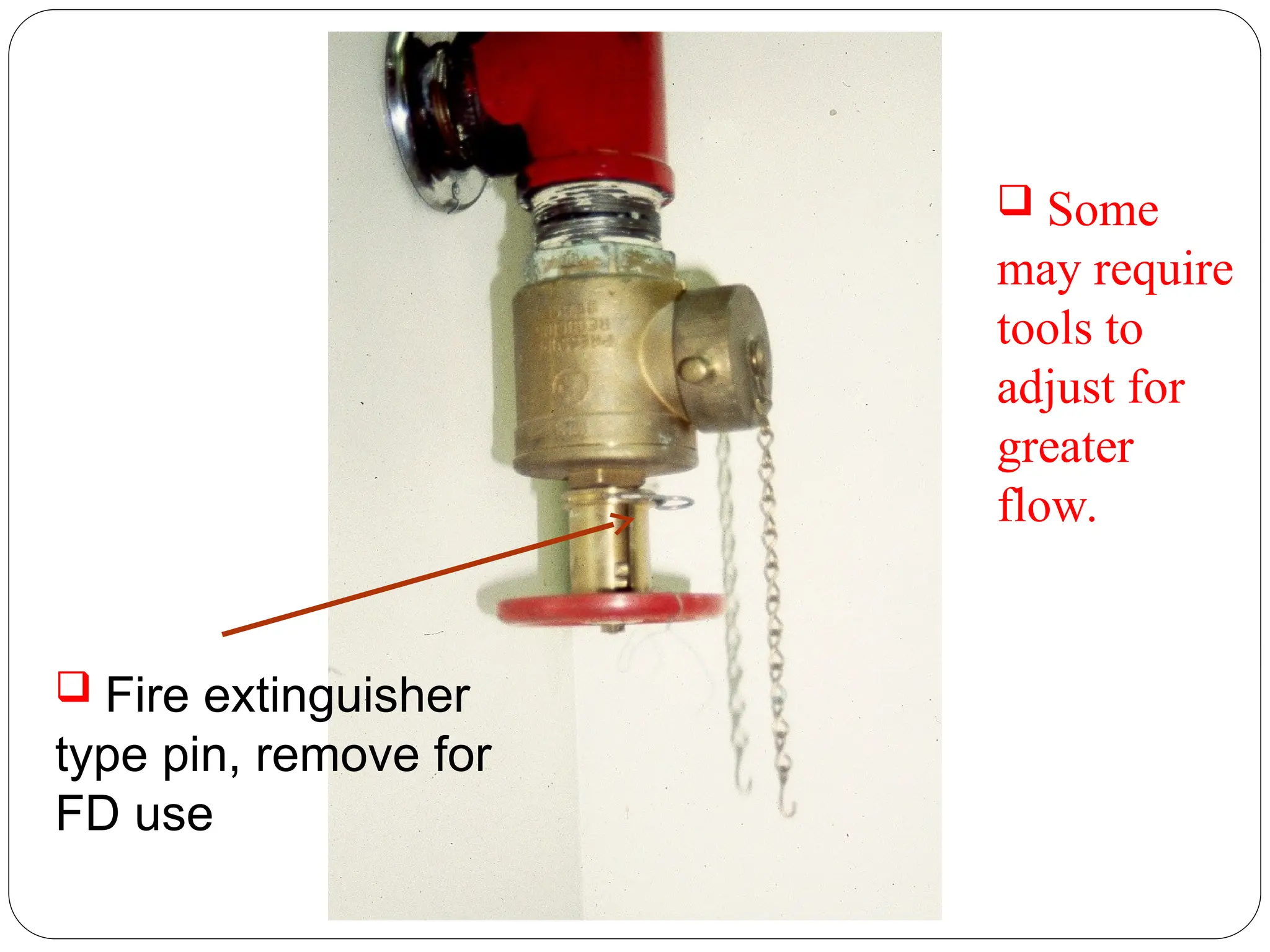
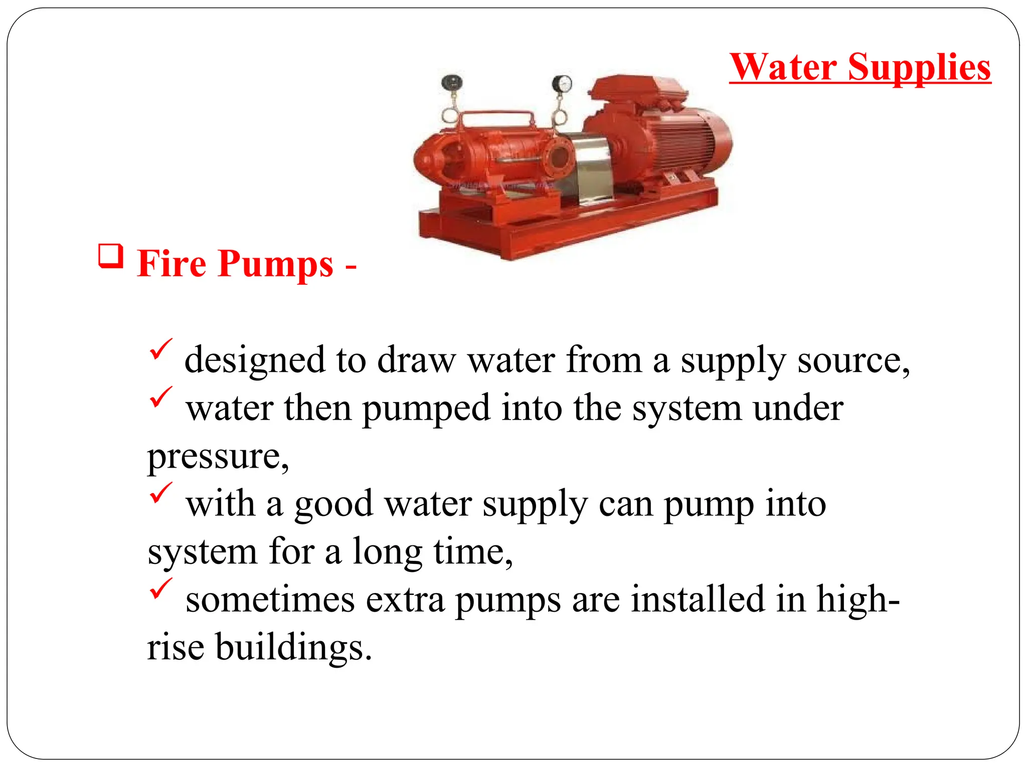
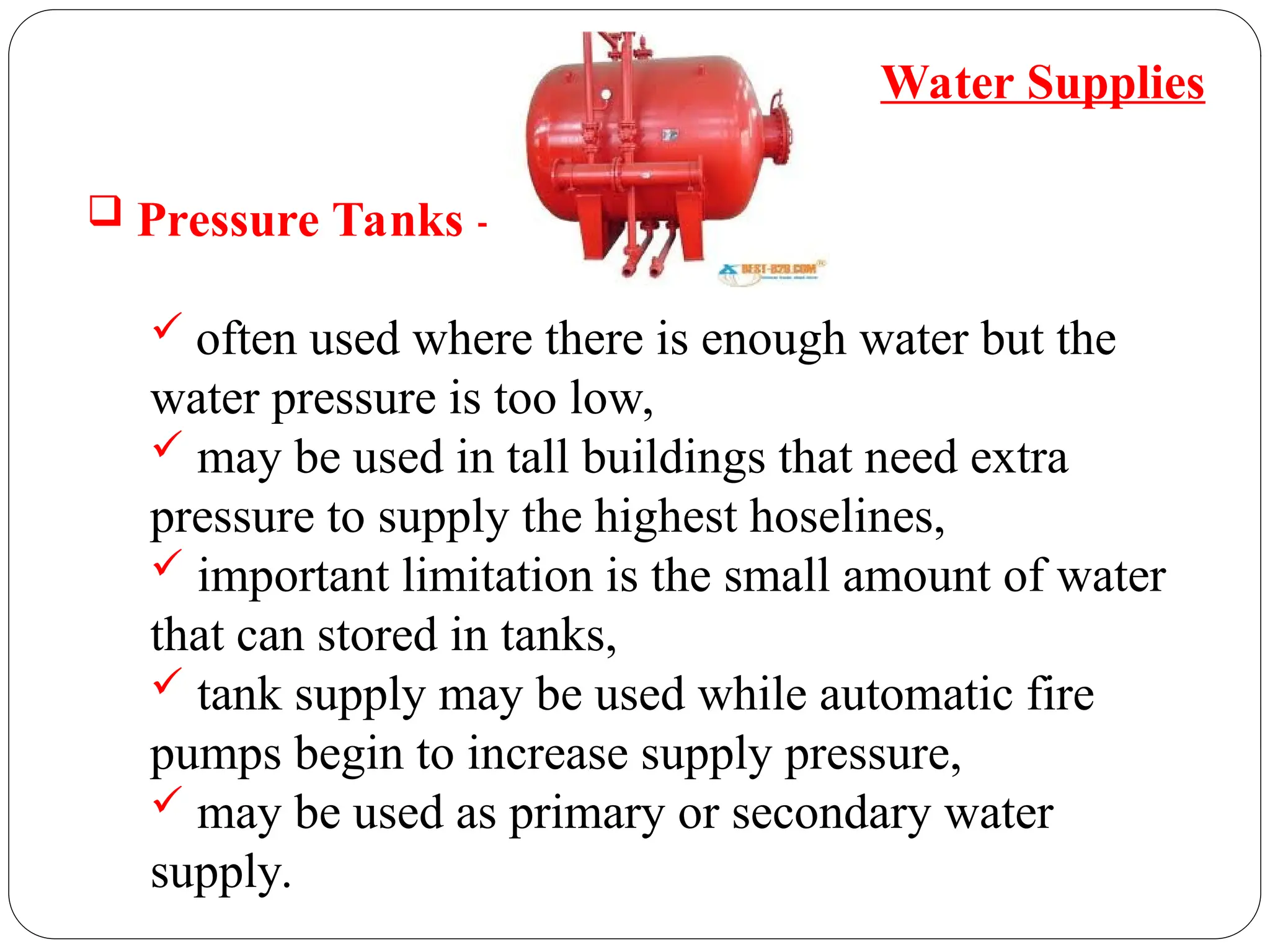
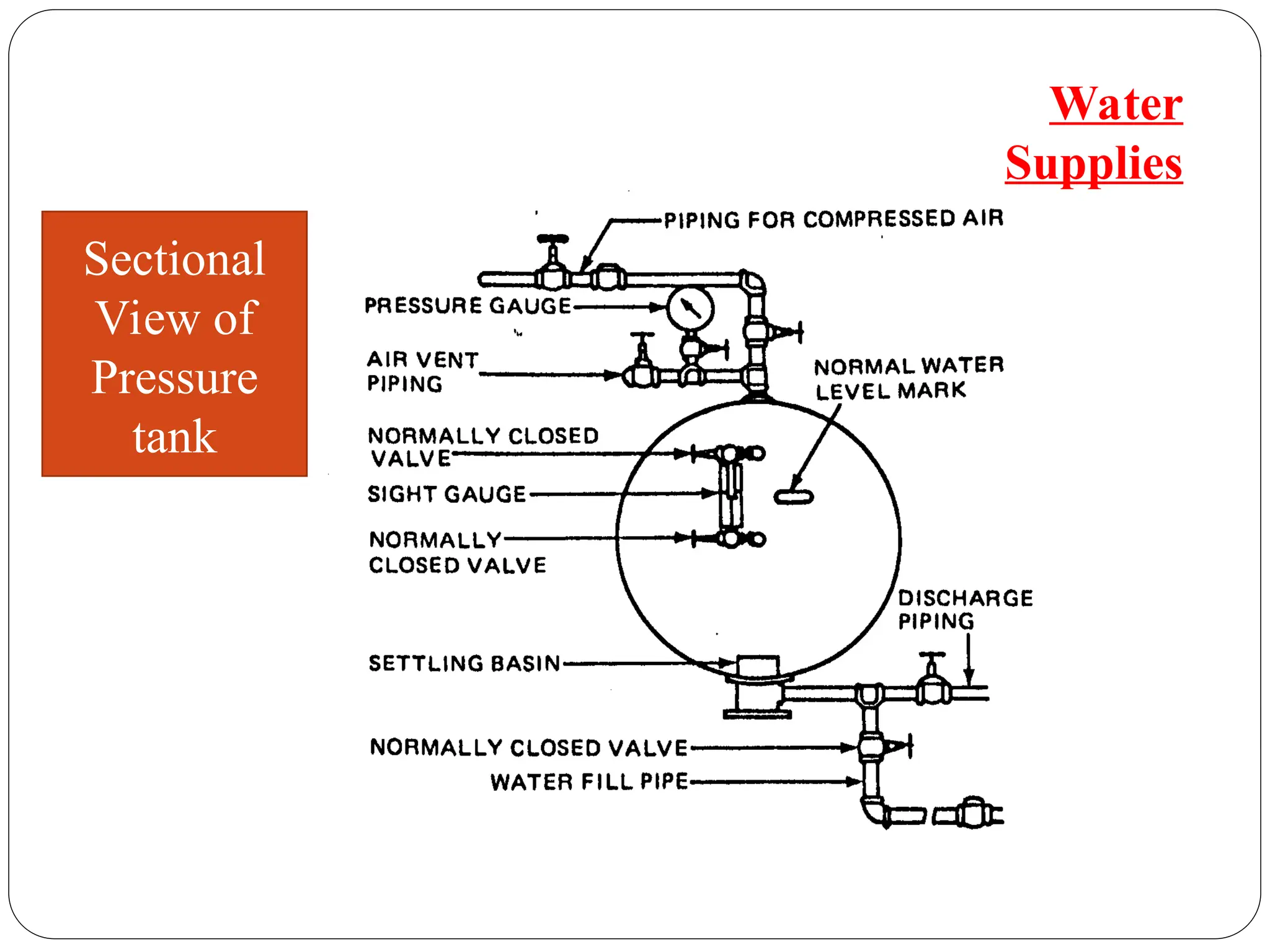
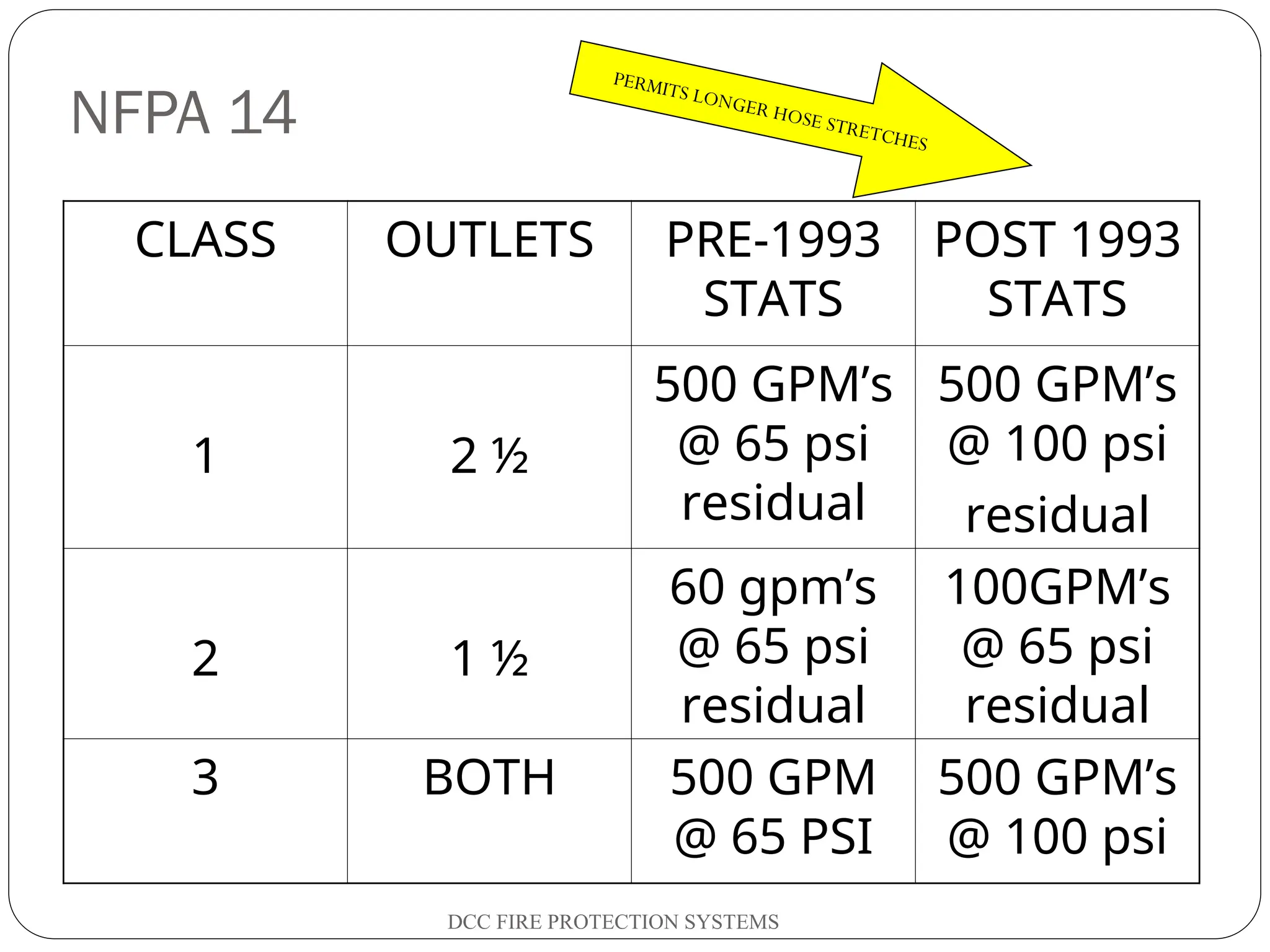
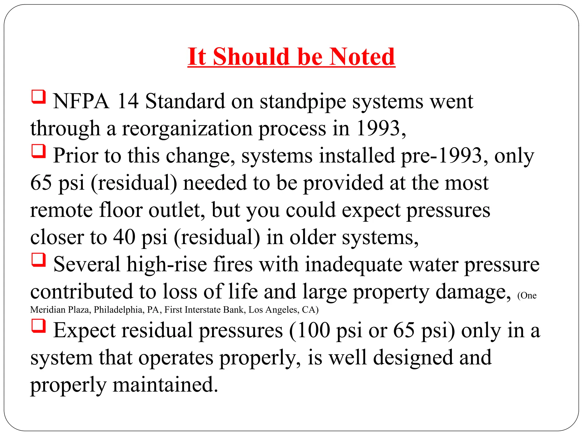
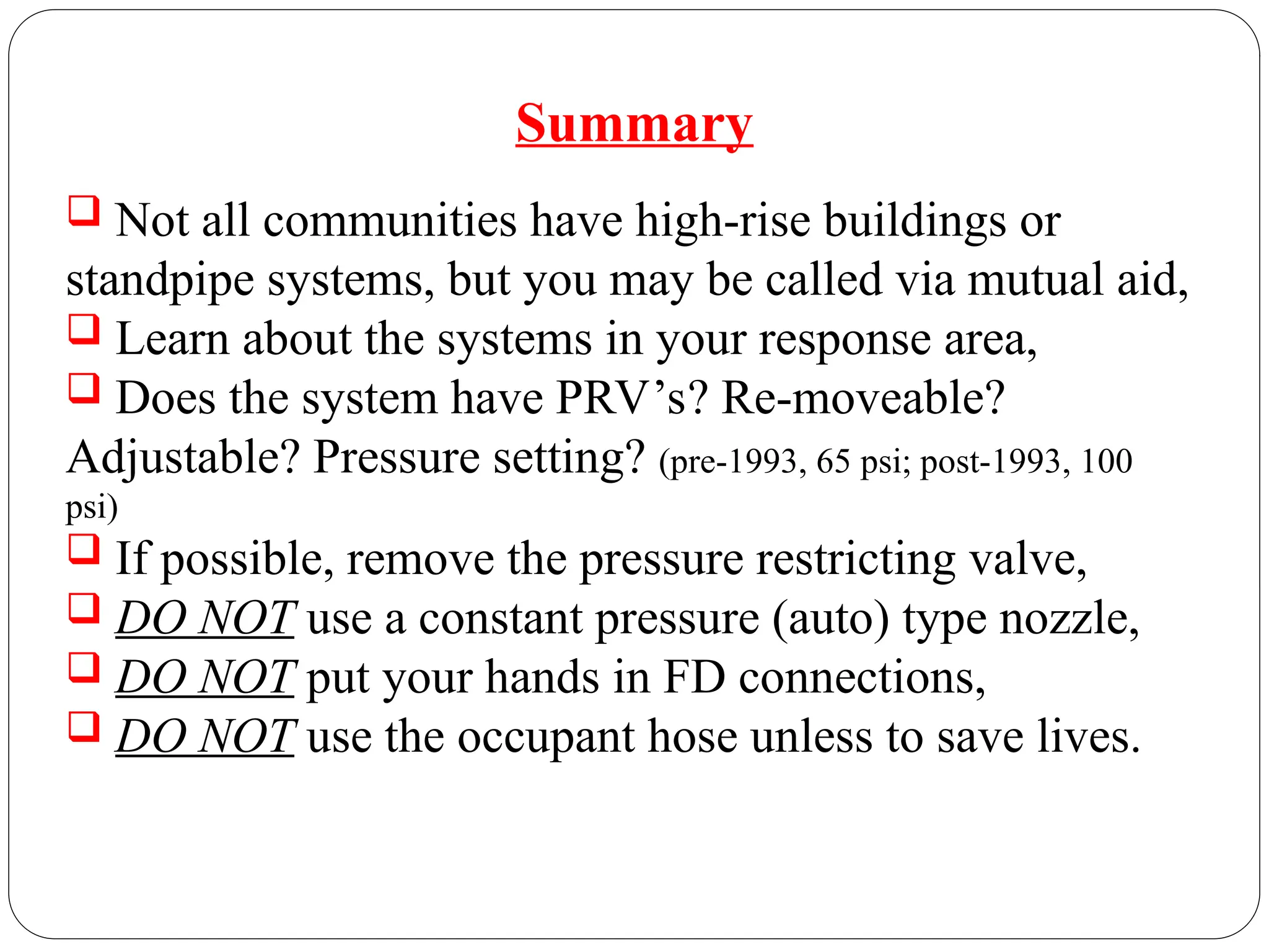
“FIRE STANDPIPE SYSTEMS”
Standpipe Systems
 A standpipe system is a fire safety system which is
designed to provide rapid access to water in the event
that a fire breaks out.
 Standpipes are installed as stand-alone systems
which act like building specific fire hydrants,
providing fire protection which will be readily
available to fire fighters.
What is a Standpipe System
History
 Standpipe systems have been part of our
firefighting arsenal for more than 100 years.
 The basic concept of a standpipe system has not
changed extensively since the original NFPA standard
was adopted in 1915.
Standpipe System
 Systems are used in high-rise buildings, large
commercial, retail, and industrial buildings; places
of public assembly, and other areas where
advancing hoselines would be difficult due to the
building size.
 Tunnels, such as subways, and shopping malls
have a horizontal standpipe system.
 Underground buildings, heliports, marinas and
boat yards.
Installations Standpipe System
 Standpipes are one of the simplest and basic of
water delivery systems.
 Designed to deliver water for manual fire-fighting;
 via fixed piping system,
 will eliminate hose lays,
 and decrease time to deliver water on the fire.
Standpipe System
 Standpipes have several main components;
 Water Supplies;
 municipal or private water mains,
 gravity tanks,
 pressure tanks,
 fire pumps.
 Siamese connections,
 Risers,
 Cross connections,
 Valves,
 Hose outlets.
Standpipe System
 Systems are installed in accordance with NFPA 14
“Standard for the Installation of Standpipes and
Hose Systems” and any local adopted codes.
 Water supply must be established and maintained
for 30 minutes.
 System and appurtenances are subject to
acceptance tests.
 All new systems must be tested and approved
before allowing building occupancy.
Standpipe System
 System is subject to hydrostatic testing;
 for two hours at 200 psi, or
 where maximum pressure is 150 psi, tested
at 50 psi above highest pressure.
 System is subject to a flow test;
 2 ½” maximum flow of 250 gpm,
 1 ½” maximum flow of 100 gpm.
 max pressure at any point in the
system at any time not exceed 350 psi.
Standpipe System
 Systems are subjected to additional codes in
accordance with;
 NFPA 25 “Standard for the Inspection,
Testing and Maintenance of Water-Based
Fire Protection Systems”.
 NFPA 1962 “Standard for the Inspection,
Care, and Use of Fire Hose, Couplings, and
Nozzles and the Service Testing of Fire
Hose”.
Standpipe System
 NFPA 22 “Standard for Water Tanks for
Private Fire Protection”
 NFPA 72 “National Fire Alarm Code”
 State and Local codes.
Standpipe System
Types of Standpipe Systems
Types of Systems
 There are five types of systems. Basically, they are
either “wet” or “dry”.
 Automatic wet;
 water in pipe with a water supply.
 Automatic dry;
 air or nitrogen in pipe with a water supply.
 Semi-automatic dry;
 air in pipe, deluge valve with a water supply.
 Manual dry;
 air in pipe with no water supply.
 Manual wet;
 water in pipe with no water supply.
Note: Combinations systems consist of sprinkler
systems interconnected with a standpipe system,
most of these systems are “wet”.
Types of Systems
Classes of Systems
Classes of Systems
 A Class I System –
 2 ½” (65 mm) hose connection;
 used by personnel trained for heavy stream
operation,
 designed to deliver 500 gpm’s at 1st
riser and
250 gpm’s at each additional riser,
 flow to be residual 100 psi at highest hose
station, (pre 1993 systems residual 65 psi)
 bldgs not classified as High-Rise, system can
be auto wet, auto dry, manual wet or manual dry,
 high-rise system must be auto or semi-auto wet
except where subject to freezing.
 A Class I System - 2 ½” hose connection.
 No Hose, designed for FD Use.
 No pressure
reducing valve
present.
 Class I Systems
 A Class II System –
 1 ½” (40mm) hose station;
 used by building occupants/FD,
 100 gpm’s at 100 psi, (65 psi for pre-1993
systems) residual outlet pressure,
 auto wet system unless subject to freezing,
 auto dry or semi-auto dry allowed where fire
brigade trained to operate w/o FD intervention.
Classes of System
 Class II Systems
 A Class II System -
 in the corridor,
 accessible to the occupants,
 not more than 100 feet of 1 ½” (40 mm) hose and
30 foot stream,
 1” (25.4 mm) hose permitted in light hazard
occupancies,
 reduced water supply.
Classes of System
Class II Locations
Classes of System
100 feet of hose and
a 30 foot stream
Additional
standpipes
required
 A Class III System –
 2 ½” (65 mm) hose connection and a 1 ½” (40 mm)
hose station. (features of both Class I and II);
 auto wet system unless subject to freezing,
 auto dry or semi-auto dry allowed where fire
brigade trained to operate w/o FD intervention,
 not more than 100 ft. of 1 ½” (40 mm) hose,
Classes of System
 Class III System
Class I and III locations -
 Class III system;
 highest/lowest floor level >30’ of FD vehicle
access, (2010 NYSFC)
 Class I system;
 in every required stairway, (2010 NYSFC)
 intermediate floor landing, unless approved by local
CEO, (2010 NYSFC)
 each side of a horizontal exit,
 at entrance to grade level passageways,
 at the roof or highest landing based on slope,
 any area greater than 150 feet in un-sprinklered or
200 feet sprinklered building.
Classes of System
Horizontal
Exit
If more than
150 feet un-sprinklered
200 sprinklered
If stair goes to the roof and
the roof is 4:12 or less a hose
connection on the roof or top
landing is required
Located at intermediate
landings
Class I location
Classes of System
 fire codes now require
Class I standpipe hose
station outlets at the highest
intermediate landing
between floor levels in every
required exit stairway as the
picture illustrates.
Classes of System
 A Class III System –
 1 ½″ hose connection
2 ½″ hose connection
 Horizontal Exit -
 The horizontal exit must have a minimum 2-hour
fire resistance rating, and the openings in it must be
rated at least 1-1/2-hours.
 Providing standpipe hose outlets on both sides of the
horizontal exit gives firefighters a refuge while fighting
a fire on the opposite side of the fire barrier.
Fire Department Connections
 Fire Department Connections -
 allows FD to pump supplemental water for
automatic systems and primary water for manual
systems,
 shall be visible and recognizable,
 located and arranged so that hose lines can be
attached without interference,
 min size of fittings 2 ½” (65 mm) (FCNYS),
 have a sign with at least 1” letters that read
“STANDPIPE”,
 shall not be less than 18” or more than 48” above
grade.
 No shut off valves between the
FD connection and the system
allowed.
Pressure Regulating Devices
 Pressure-Regulating Device; a device designed for
the purpose of reducing, regulating, controlling, or
restricting water pressure, static and residual.
 Pressure-Restricting Device; a valve or device
designed for the purpose of reducing the downstream
water pressure under flowing (residual) conditions
only.
 Definition of Pressure Devices -
Pressure Regulating Devices
 Residual Pressure –
 pressure acting on a point in the system with a
flow being delivered,
 where the residual pressure at an 1 ½” (40 mm)
outlet on a hose connection exceeds 100 psi (6.9
bar), a pressure regulating device shall be provided
to limit the residual pressure at the flow to 100
psi. (6.9 bar)
Pressure Regulating Devices
 Static Pressure –
 pressure acting on a point in the system with no
flow being delivered,
 where static pressure at a hose connection
exceeds 175 psi (12.1 bar), a pressure regulating
device provided to limit static and residual
pressure at the outlet of the hose connection to
100 psi (6.9 bar) for 1 ½” (40 mm) hose and 175 psi
(12.1 bar) for other hose connections.
Pressure Regulating Devices
 Pressure Regulating Devices -
 NFPA 14 stipulates the maximum pressure at any
point in the system at any time shall not exceed 350
psi. (24 bar) (2413 kPa),
 critical components in the systems are valves
categorized as pressure-regulating devices;
 they must be properly set and installed so that
proper pressure is maintained at the hose outlet,
 improperly set valves can result in inadequate
streams or an uncontrollable amount of pressure,
 there are two methods of setting outlet pressure:
field set and factory set.
Standpipe Pressure
Regulating Valve
Outlet Reducer
(restricting device)
Pressure
Regulating
Valves
Tab restricts how
far valve opens
 Pressure
Regulating Valves,
Non-Removable
Tab moved for FD
use
 Must be bypassed
for FD use
 Fire extinguisher
type pin, remove for
FD use
 Some
may require
tools to
adjust for
greater
flow.
 Pilot operated valves-
Restrict pressure under
flow and static
conditions
 In one survey by
a large US city,
75% failed to
deliver a fire stream
!!
Diaphragm
pushes valve
closed if inlet
pressure
rises
Factory set
spring sets
maximum size
of valve
opening
Water Supplies
Standpipe System Water Supplies
 Acceptable water supplies include;
 public or private water mains,
 gravity tanks,
 fire pumps,
 and pressure tanks.
Water Supplies
Municipal or Private
Water Supply
Gravity Tanks
Fire Pump
Pressure Tank
 Public/Private Water Mains
Water Supplies
 Water Mains –
 most prevalent connection for standpipe system,
 might supply adequate water for high-rise
buildings, might not supply adequate pressure for
buildings higher than 10 stories,
 overcoming the pressure loss in 100’ of height
requires 43.3 psi, high-rise buildings often require
fire pumps or gravity tanks,
Water Supplies
 Gravity Tanks -
 Tank materials limited to:
 steel, wood, concrete, coated fabrics and fiberglass
reinforced plastic.
 Standard sizes:
 wood – 5,000 to 100,000 gals,
 steel – 5,000 to 500,000 gals,
 factory coated/bolted steel – 4,000 to 500,000 gals,
 pre-stressed concrete - 10,000 to 1,000,000 gals,
 reinforced concrete - 10,000 to 500,000 gals.
Water Supplies
 Gravity Tanks –
 of adequate capacity and elevation make a good
primary supply,
 may be located on top of a building or on a tall
tower,
 water is distributed throughout system by pull of
gravity.
Water Supplies
Water Supplies
Gravity Tank
 Fire Pumps -
 designed to draw water from a supply source,
 water then pumped into the system under
pressure,
 with a good water supply can pump into
system for a long time,
 sometimes extra pumps are installed in high-
rise buildings.
Water Supplies
 Fire Pumps –
 supply the pressure needed to ensure adequate
water volume at efficient pressure,
 two types of pumps, Automatic and Manual,
 automatic pump usually arranged with the
controller on a pressure drop or waterflow in the
standpipe,
Water Supplies
 Building fire pumps are designed to produce a
limited pressure at the top floor outlets.
 Pressure Tanks -
 often used where there is enough water but the
water pressure is too low,
 may be used in tall buildings that need extra
pressure to supply the highest hoselines,
 important limitation is the small amount of water
that can stored in tanks,
 tank supply may be used while automatic fire
pumps begin to increase supply pressure,
 may be used as primary or secondary water
supply.
Water Supplies
 Pressure Tanks -
 are enclosed water tanks of limited size,
 air pressure within the tank provides velocity for
discharging water from the tank,
 normally 2/3 filled with water, charged with a min
75 psi.,
 usually housed in an enclosed heated structure,
 may be located anywhere in the building or outside
the building,
 max capacity of pressure tanks is typically 9,000
gallons.
Water Supplies
Water
Supplies
Sectional
View of
Pressure
tank
Pressure Hydraulics
 Pressure –
 pressure is a measure of force acting over an area,
 measured in terms of “feet of head” or “pounds
per square inch”,
 a column of water 12” high and 1” sq.,
weighs .434 pounds per sq. inch, no matter what area
of the container.
Hydraulics
 one cubic foot of water totals 1728 cubic
inches,
 there are 144 sq, inch columns of water in a
cubic foot, each weighing .434 lbs,
 e.g. 144 x .434 = 62,496 lbs, ( one
cubic foot = 62.5 lbs.,
 one gallon of water contains 231
cubic inches,
 divide 231 cubic inches into 1728 cubic
inches = 7.481 gals in one cubic foot of water.
Hydraulics
 if the total weight of a cubic foot of water is 62.5
lbs, divide that by 7.481 gals = 8.35 lbs per gal.
 what does all this mean?
 delivering 250 gpm to an upper floor of a
building through the standpipe system will require
lifting more than a ton of water per minute from the
street to the fire floor.
Hydraulics
Standpipe Operations
 Supplying the system;
 through the fire dept connection and/or floor
outlets,
 use 2 ½” or larger diameter hose,
 when possible, supplied by two different
pumpers,
 when possible, supply two independent FD
connections,
 if building is equipped with a sprinkler and a
standpipe, first supply line to feed the standpipe.
Standpipe Operations
 Operating from;
 bring your standpipe kit,
 bring 200’ of 2 ½” hose with smooth bore or
combination nozzle,
 DO NOT use constant pressure (automatic type)
spray nozzles, many require 100 psi at the nozzle
inlet,
 stretch from the intermediate floor level landing
or the floor below the fire floor,
 flush system before hookup,
 bleed the nozzle before entry into fire area.
DCC FIRE PROTECTION SYSTEMS
NFPA 14
CLASS OUTLETS PRE-1993
STATS
POST 1993
STATS
1 2 ½
500 GPM’s
@ 65 psi
residual
500 GPM’s
@ 100 psi
residual
2 1 ½
60 gpm’s
@ 65 psi
residual
100GPM’s
@ 65 psi
residual
3 BOTH 500 GPM
@ 65 PSI
500 GPM’s
@ 100 psi
PERMITS LONGER HOSE STRETCHES
Standpipe Operations
 Standpipe Kit (sample);
 metal or plastic tool box or soft-sided bag,
 an additional controlling nozzle,
 one 2 ½” - 30ₒ
or 45ₒ
elbow,
 one 2 ½” in-line pressure gauge,
 2 hose straps, a pair of vise grips, a shove knife,
 2 wooden chocks, 2 latch straps,
 18 - 20” pipe wrench, 2 operating wheels,
 a wire brush, a plumbers strap,
 a 2 ½” adapter, pipe thread to local FD threads,
 a 2 ½” cap, 2 spanner wrenches.
It Should be Noted
 NFPA 14 Standard on standpipe systems went
through a reorganization process in 1993,
 Prior to this change, systems installed pre-1993, only
65 psi (residual) needed to be provided at the most
remote floor outlet, but you could expect pressures
closer to 40 psi (residual) in older systems,
 Several high-rise fires with inadequate water pressure
contributed to loss of life and large property damage, (One
Meridian Plaza, Philadelphia, PA, First Interstate Bank, Los Angeles, CA)
 Expect residual pressures (100 psi or 65 psi) only in a
system that operates properly, is well designed and
properly maintained.
One Meridian Plaza, February 23, 1991
Summary
 Not all communities have high-rise buildings or
standpipe systems, but you may be called via mutual aid,
 Learn about the systems in your response area,
 Does the system have PRV’s? Re-moveable?
Adjustable? Pressure setting? (pre-1993, 65 psi; post-1993, 100
psi)
 If possible, remove the pressure restricting valve,
 DO NOT use a constant pressure (auto) type nozzle,
 DO NOT put your hands in FD connections,
 DO NOT use the occupant hose unless to save lives.
Prepared by Thomas Bartsch
Chief Fire Inspector (ret.)
A special thank you to David K. Walsh, Program Chair,
Dutchess Community College Fire Science Program
for his contribution in the preparation of this presentation.

Fire Standpipe SystemsTBartsch we are.ppt

  • 1.
  • 2.
  • 3.
     A standpipesystem is a fire safety system which is designed to provide rapid access to water in the event that a fire breaks out.  Standpipes are installed as stand-alone systems which act like building specific fire hydrants, providing fire protection which will be readily available to fire fighters. What is a Standpipe System
  • 4.
    History  Standpipe systemshave been part of our firefighting arsenal for more than 100 years.  The basic concept of a standpipe system has not changed extensively since the original NFPA standard was adopted in 1915. Standpipe System
  • 5.
     Systems areused in high-rise buildings, large commercial, retail, and industrial buildings; places of public assembly, and other areas where advancing hoselines would be difficult due to the building size.  Tunnels, such as subways, and shopping malls have a horizontal standpipe system.  Underground buildings, heliports, marinas and boat yards. Installations Standpipe System
  • 6.
     Standpipes areone of the simplest and basic of water delivery systems.  Designed to deliver water for manual fire-fighting;  via fixed piping system,  will eliminate hose lays,  and decrease time to deliver water on the fire. Standpipe System
  • 7.
     Standpipes haveseveral main components;  Water Supplies;  municipal or private water mains,  gravity tanks,  pressure tanks,  fire pumps.  Siamese connections,  Risers,  Cross connections,  Valves,  Hose outlets. Standpipe System
  • 9.
     Systems areinstalled in accordance with NFPA 14 “Standard for the Installation of Standpipes and Hose Systems” and any local adopted codes.  Water supply must be established and maintained for 30 minutes.  System and appurtenances are subject to acceptance tests.  All new systems must be tested and approved before allowing building occupancy. Standpipe System
  • 10.
     System issubject to hydrostatic testing;  for two hours at 200 psi, or  where maximum pressure is 150 psi, tested at 50 psi above highest pressure.  System is subject to a flow test;  2 ½” maximum flow of 250 gpm,  1 ½” maximum flow of 100 gpm.  max pressure at any point in the system at any time not exceed 350 psi. Standpipe System
  • 11.
     Systems aresubjected to additional codes in accordance with;  NFPA 25 “Standard for the Inspection, Testing and Maintenance of Water-Based Fire Protection Systems”.  NFPA 1962 “Standard for the Inspection, Care, and Use of Fire Hose, Couplings, and Nozzles and the Service Testing of Fire Hose”. Standpipe System
  • 12.
     NFPA 22“Standard for Water Tanks for Private Fire Protection”  NFPA 72 “National Fire Alarm Code”  State and Local codes. Standpipe System
  • 13.
  • 14.
    Types of Systems There are five types of systems. Basically, they are either “wet” or “dry”.  Automatic wet;  water in pipe with a water supply.  Automatic dry;  air or nitrogen in pipe with a water supply.
  • 15.
     Semi-automatic dry; air in pipe, deluge valve with a water supply.  Manual dry;  air in pipe with no water supply.  Manual wet;  water in pipe with no water supply. Note: Combinations systems consist of sprinkler systems interconnected with a standpipe system, most of these systems are “wet”. Types of Systems
  • 16.
  • 17.
    Classes of Systems A Class I System –  2 ½” (65 mm) hose connection;  used by personnel trained for heavy stream operation,  designed to deliver 500 gpm’s at 1st riser and 250 gpm’s at each additional riser,  flow to be residual 100 psi at highest hose station, (pre 1993 systems residual 65 psi)  bldgs not classified as High-Rise, system can be auto wet, auto dry, manual wet or manual dry,  high-rise system must be auto or semi-auto wet except where subject to freezing.
  • 18.
     A ClassI System - 2 ½” hose connection.  No Hose, designed for FD Use.  No pressure reducing valve present.
  • 19.
     Class ISystems
  • 20.
     A ClassII System –  1 ½” (40mm) hose station;  used by building occupants/FD,  100 gpm’s at 100 psi, (65 psi for pre-1993 systems) residual outlet pressure,  auto wet system unless subject to freezing,  auto dry or semi-auto dry allowed where fire brigade trained to operate w/o FD intervention. Classes of System
  • 21.
     Class IISystems
  • 22.
     A ClassII System -  in the corridor,  accessible to the occupants,  not more than 100 feet of 1 ½” (40 mm) hose and 30 foot stream,  1” (25.4 mm) hose permitted in light hazard occupancies,  reduced water supply. Classes of System
  • 23.
    Class II Locations Classesof System 100 feet of hose and a 30 foot stream Additional standpipes required
  • 24.
     A ClassIII System –  2 ½” (65 mm) hose connection and a 1 ½” (40 mm) hose station. (features of both Class I and II);  auto wet system unless subject to freezing,  auto dry or semi-auto dry allowed where fire brigade trained to operate w/o FD intervention,  not more than 100 ft. of 1 ½” (40 mm) hose, Classes of System
  • 25.
  • 26.
    Class I andIII locations -  Class III system;  highest/lowest floor level >30’ of FD vehicle access, (2010 NYSFC)  Class I system;  in every required stairway, (2010 NYSFC)  intermediate floor landing, unless approved by local CEO, (2010 NYSFC)  each side of a horizontal exit,  at entrance to grade level passageways,  at the roof or highest landing based on slope,  any area greater than 150 feet in un-sprinklered or 200 feet sprinklered building. Classes of System
  • 27.
    Horizontal Exit If more than 150feet un-sprinklered 200 sprinklered If stair goes to the roof and the roof is 4:12 or less a hose connection on the roof or top landing is required Located at intermediate landings Class I location Classes of System
  • 28.
     fire codesnow require Class I standpipe hose station outlets at the highest intermediate landing between floor levels in every required exit stairway as the picture illustrates. Classes of System
  • 29.
     A ClassIII System –  1 ½″ hose connection 2 ½″ hose connection
  • 30.
     Horizontal Exit-  The horizontal exit must have a minimum 2-hour fire resistance rating, and the openings in it must be rated at least 1-1/2-hours.  Providing standpipe hose outlets on both sides of the horizontal exit gives firefighters a refuge while fighting a fire on the opposite side of the fire barrier.
  • 31.
  • 32.
     Fire DepartmentConnections -  allows FD to pump supplemental water for automatic systems and primary water for manual systems,  shall be visible and recognizable,  located and arranged so that hose lines can be attached without interference,  min size of fittings 2 ½” (65 mm) (FCNYS),  have a sign with at least 1” letters that read “STANDPIPE”,  shall not be less than 18” or more than 48” above grade.
  • 33.
     No shutoff valves between the FD connection and the system allowed.
  • 34.
  • 35.
     Pressure-Regulating Device;a device designed for the purpose of reducing, regulating, controlling, or restricting water pressure, static and residual.  Pressure-Restricting Device; a valve or device designed for the purpose of reducing the downstream water pressure under flowing (residual) conditions only.  Definition of Pressure Devices - Pressure Regulating Devices
  • 36.
     Residual Pressure–  pressure acting on a point in the system with a flow being delivered,  where the residual pressure at an 1 ½” (40 mm) outlet on a hose connection exceeds 100 psi (6.9 bar), a pressure regulating device shall be provided to limit the residual pressure at the flow to 100 psi. (6.9 bar) Pressure Regulating Devices
  • 37.
     Static Pressure–  pressure acting on a point in the system with no flow being delivered,  where static pressure at a hose connection exceeds 175 psi (12.1 bar), a pressure regulating device provided to limit static and residual pressure at the outlet of the hose connection to 100 psi (6.9 bar) for 1 ½” (40 mm) hose and 175 psi (12.1 bar) for other hose connections. Pressure Regulating Devices
  • 38.
     Pressure RegulatingDevices -  NFPA 14 stipulates the maximum pressure at any point in the system at any time shall not exceed 350 psi. (24 bar) (2413 kPa),  critical components in the systems are valves categorized as pressure-regulating devices;  they must be properly set and installed so that proper pressure is maintained at the hose outlet,  improperly set valves can result in inadequate streams or an uncontrollable amount of pressure,  there are two methods of setting outlet pressure: field set and factory set.
  • 39.
    Standpipe Pressure Regulating Valve OutletReducer (restricting device)
  • 40.
  • 41.
    Tab restricts how farvalve opens  Pressure Regulating Valves, Non-Removable Tab moved for FD use  Must be bypassed for FD use
  • 43.
     Fire extinguisher typepin, remove for FD use  Some may require tools to adjust for greater flow.
  • 44.
     Pilot operatedvalves- Restrict pressure under flow and static conditions  In one survey by a large US city, 75% failed to deliver a fire stream !!
  • 45.
    Diaphragm pushes valve closed ifinlet pressure rises Factory set spring sets maximum size of valve opening
  • 46.
  • 47.
    Standpipe System WaterSupplies  Acceptable water supplies include;  public or private water mains,  gravity tanks,  fire pumps,  and pressure tanks.
  • 48.
    Water Supplies Municipal orPrivate Water Supply Gravity Tanks Fire Pump Pressure Tank
  • 49.
     Public/Private WaterMains Water Supplies
  • 50.
     Water Mains–  most prevalent connection for standpipe system,  might supply adequate water for high-rise buildings, might not supply adequate pressure for buildings higher than 10 stories,  overcoming the pressure loss in 100’ of height requires 43.3 psi, high-rise buildings often require fire pumps or gravity tanks, Water Supplies
  • 51.
     Gravity Tanks-  Tank materials limited to:  steel, wood, concrete, coated fabrics and fiberglass reinforced plastic.  Standard sizes:  wood – 5,000 to 100,000 gals,  steel – 5,000 to 500,000 gals,  factory coated/bolted steel – 4,000 to 500,000 gals,  pre-stressed concrete - 10,000 to 1,000,000 gals,  reinforced concrete - 10,000 to 500,000 gals. Water Supplies
  • 52.
     Gravity Tanks–  of adequate capacity and elevation make a good primary supply,  may be located on top of a building or on a tall tower,  water is distributed throughout system by pull of gravity. Water Supplies
  • 53.
  • 54.
     Fire Pumps-  designed to draw water from a supply source,  water then pumped into the system under pressure,  with a good water supply can pump into system for a long time,  sometimes extra pumps are installed in high- rise buildings. Water Supplies
  • 55.
     Fire Pumps–  supply the pressure needed to ensure adequate water volume at efficient pressure,  two types of pumps, Automatic and Manual,  automatic pump usually arranged with the controller on a pressure drop or waterflow in the standpipe, Water Supplies
  • 56.
     Building firepumps are designed to produce a limited pressure at the top floor outlets.
  • 57.
     Pressure Tanks-  often used where there is enough water but the water pressure is too low,  may be used in tall buildings that need extra pressure to supply the highest hoselines,  important limitation is the small amount of water that can stored in tanks,  tank supply may be used while automatic fire pumps begin to increase supply pressure,  may be used as primary or secondary water supply. Water Supplies
  • 58.
     Pressure Tanks-  are enclosed water tanks of limited size,  air pressure within the tank provides velocity for discharging water from the tank,  normally 2/3 filled with water, charged with a min 75 psi.,  usually housed in an enclosed heated structure,  may be located anywhere in the building or outside the building,  max capacity of pressure tanks is typically 9,000 gallons. Water Supplies
  • 59.
  • 60.
  • 61.
     Pressure – pressure is a measure of force acting over an area,  measured in terms of “feet of head” or “pounds per square inch”,  a column of water 12” high and 1” sq., weighs .434 pounds per sq. inch, no matter what area of the container. Hydraulics
  • 62.
     one cubicfoot of water totals 1728 cubic inches,  there are 144 sq, inch columns of water in a cubic foot, each weighing .434 lbs,  e.g. 144 x .434 = 62,496 lbs, ( one cubic foot = 62.5 lbs.,  one gallon of water contains 231 cubic inches,  divide 231 cubic inches into 1728 cubic inches = 7.481 gals in one cubic foot of water. Hydraulics
  • 63.
     if thetotal weight of a cubic foot of water is 62.5 lbs, divide that by 7.481 gals = 8.35 lbs per gal.  what does all this mean?  delivering 250 gpm to an upper floor of a building through the standpipe system will require lifting more than a ton of water per minute from the street to the fire floor. Hydraulics
  • 64.
  • 65.
    Standpipe Operations  Supplyingthe system;  through the fire dept connection and/or floor outlets,  use 2 ½” or larger diameter hose,  when possible, supplied by two different pumpers,  when possible, supply two independent FD connections,  if building is equipped with a sprinkler and a standpipe, first supply line to feed the standpipe.
  • 66.
    Standpipe Operations  Operatingfrom;  bring your standpipe kit,  bring 200’ of 2 ½” hose with smooth bore or combination nozzle,  DO NOT use constant pressure (automatic type) spray nozzles, many require 100 psi at the nozzle inlet,  stretch from the intermediate floor level landing or the floor below the fire floor,  flush system before hookup,  bleed the nozzle before entry into fire area.
  • 67.
    DCC FIRE PROTECTIONSYSTEMS NFPA 14 CLASS OUTLETS PRE-1993 STATS POST 1993 STATS 1 2 ½ 500 GPM’s @ 65 psi residual 500 GPM’s @ 100 psi residual 2 1 ½ 60 gpm’s @ 65 psi residual 100GPM’s @ 65 psi residual 3 BOTH 500 GPM @ 65 PSI 500 GPM’s @ 100 psi PERMITS LONGER HOSE STRETCHES
  • 68.
    Standpipe Operations  StandpipeKit (sample);  metal or plastic tool box or soft-sided bag,  an additional controlling nozzle,  one 2 ½” - 30ₒ or 45ₒ elbow,  one 2 ½” in-line pressure gauge,  2 hose straps, a pair of vise grips, a shove knife,  2 wooden chocks, 2 latch straps,  18 - 20” pipe wrench, 2 operating wheels,  a wire brush, a plumbers strap,  a 2 ½” adapter, pipe thread to local FD threads,  a 2 ½” cap, 2 spanner wrenches.
  • 69.
    It Should beNoted  NFPA 14 Standard on standpipe systems went through a reorganization process in 1993,  Prior to this change, systems installed pre-1993, only 65 psi (residual) needed to be provided at the most remote floor outlet, but you could expect pressures closer to 40 psi (residual) in older systems,  Several high-rise fires with inadequate water pressure contributed to loss of life and large property damage, (One Meridian Plaza, Philadelphia, PA, First Interstate Bank, Los Angeles, CA)  Expect residual pressures (100 psi or 65 psi) only in a system that operates properly, is well designed and properly maintained.
  • 70.
    One Meridian Plaza,February 23, 1991
  • 71.
    Summary  Not allcommunities have high-rise buildings or standpipe systems, but you may be called via mutual aid,  Learn about the systems in your response area,  Does the system have PRV’s? Re-moveable? Adjustable? Pressure setting? (pre-1993, 65 psi; post-1993, 100 psi)  If possible, remove the pressure restricting valve,  DO NOT use a constant pressure (auto) type nozzle,  DO NOT put your hands in FD connections,  DO NOT use the occupant hose unless to save lives.
  • 72.
    Prepared by ThomasBartsch Chief Fire Inspector (ret.) A special thank you to David K. Walsh, Program Chair, Dutchess Community College Fire Science Program for his contribution in the preparation of this presentation.

Editor's Notes

  • #17 NFPA 14 – 2007 defines a High-Rise building where the floor of an occupiable story is greater than 75 ft above the lowest level of FD vehicle access.