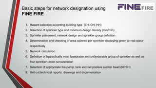
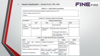
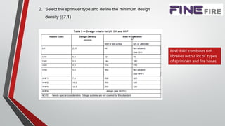
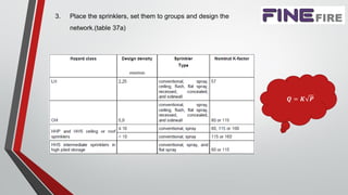
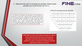
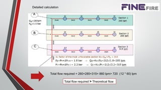
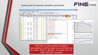
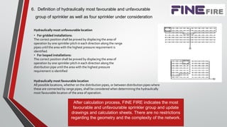
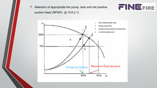
Fully calculated fire fighting systems according
EN 12845 standard
Design and calculations with 4M FINE FIRE software
Fire Department Presentation
Isidoros Siderakis
EngineeringConsultant at 4M SA
mail: isidoros@4m.gr
Athens, October 2018
Basic steps for network designation using
FINE FIRE
1. Hazard selection according building type (LH, OH, HH)
2. Selection of sprinkler type and minimum design density (mm/min)
3. Sprinkler placement, network design and sprinkler group definition
4. Determination and checking of area covered per sprinkler displaying green or red colour
respectively
5. Network calculation
6. Definition of hydraulically most favourable and unfavourable group of sprinkler as well as
four sprinkler under consideration
7. Selection of appropriate fire pump, tank and net positive suction head (NPSH)
8. Get out technical reports, drawings and documentation
1. Hazard classification – Annex A (LH, OH, HH)
2. Select the sprinkler type and define the minimum design
density (§7.1)
FINE FIRE combines rich
libraries with a lot of types
of sprinklers and fire hoses
3. Place the sprinklers, set them to groups and design the
network.(table 37a)
𝑸 = 𝑲 𝑷
Maximum coverage and spacing for sprinkler other than sidewall (table 19)
Defining the fire fighting space area, FINE FIRE
places automatically the correct number of
sprinklers in right distances, following EN 12845
criterion .
4. Determine the area of coverage per sprinkler. Check if each
sprinkler can cover its area. (§ 13.4.1)
The density of discharge shall be taken as the total flow in
litres per minute from a group of four sprinklers which are
most closely adjacent, divided by the area in square metres
covered by the four sprinklers, or, where fewer than four
sprinklers are in open communication, the density of
discharge shall be taken as the lowest value of the flow from
any sprinkler divided by the area covered by the sprinkler.
Check of coverage area per sprinkler
FINE FIRE provides automated processes in order to
check automatically the area of coverage per
sprinkler and export the drawings. Drawings
updated in order to indicate the efficient sprinkler
placemenet with juct one click.
5. Network calculations
PxK=Q
5
1,85
1,85 4,87
5 06, 10 x
P xLxQ
C dx

Hydraulic calculation taking into account Hazen-Williams formula
Detailed calculation
Total flow required = 260+285+315= 860 lpm> 720 (12 * 60) lpm
Total flow required > Theoretical flow
Detailed calculation
Inserting data and exporting calculation automatically
FINE FIRE provides detailed calculations
automatically for all the widely known standards like
EN 12845, NFPA 13, BS 9251, FM Global, AS 2118,
ASIB CEA 4001 and other.
6. Definition of hydraulically most favourable and unfavourable
group of sprinkler as well as four sprinkler under consideration
Hydraulically most unfavourable location
• For gridded installations:
The correct position shall be proved by displacing the area of
operation by one sprinkler pitch in each direction along the range
pipes until the area with the highest pressure requirement is
identified.
• For looped installations:
The correct position shall be proved by displacing the area of
operation by one sprinkler pitch in each direction along the
distribution pipe until the area with the highest pressure
requirement is identified
Hydraulically most favourable location
All possible locations, whether on the distribution pipes, or between distribution pipes where
these are connected by range pipes, shall be considered when determining the hydraulically
most favourable location of the area of operation.
After calculation process, FINE FIRE indicates the most
favourable and unfavourable sprinkler group and update
drawings and calculation sheets. There are no restrictions
regarding the geometry and the complexity of the network.
7. Selection of appropriate fire pump, tank and net positive
suction head (NPSH) (§ 10.6.2.1)
Υπόμνημα
1 Υδραυλικά δυσμενέστερη περιοχή
2 Παροχή σχεδιασμού αντλίας
3 Μέγιστη απαιτούμενη παροχή
4 Υδραυλικά ευμενέστερη περιοχή
Design pump flow Maximum flow demand
FIRE PUMP selection
Basic principles according ΕΝ 12845 (§ 10.6.2.1, 10.7.3)
 The rated duty of the pump shall be a function of the most unfavourable area curve.
A pump is chosen which:
• provides 0,5 bar higher pressure than that required for the most unfavourable area
• has a curve which extends to the point of NPSHr = 16 m
 The Max Demand Flow & Pressure of the selected pump is calculated based on the most
favourable area
 It is checked if the pump can deliver the maximum operating point at all levels of water supply
1NPSHa NPSHreq 
FINE FIRE provides detailed calculation of the Fire Pump
based on the most favourable and unfavourable groups
and NPSH check.
Schematic diagram of a Fire pump selection
8. Get out technical reports, drawings and documentation
Briefly, according paragraph 4.4.3.3, 4.4.4.4-5 for fully calculated pipework, the following
shall be given, with detailed calculations, either on purpose designed work-sheets or as a
computer printout:
a. The program name and version number
b. Detailed and dimensioned working sheets with pipes and sprinklers
c. Detailed and dimensioned working drawings
d. Detailed calculations for the automatic pump set and storage tank
FINE FIRE performs calculations generate all the
required documents in compliance with
EN 12845 the standard.
b. Detailed and dimensioned working sheets with pipes and
sprinklers
i. pipe node or other reference number
ii. the specified design density in millimetres per
minute;
iii. pressures at inlet and outlet in bar
iv. the nominal K-factor
v. Nominal diameter in mm
vi. the Hazen-Williams constant
vii. length in metres
viii. velocity in metres per second (m/s)
ix. static head change in metres
x. friction loss in bar;
xi. numbers, types and equivalent length in metres of
fittings and components
xii. indication of flow direction
i
xii
iv ii,xii vi v viii xivii x iii
ix
© 4M s/n:999723
a
FINE FIRE 14.2
a
c. Detailed and dimensioned working drawings
i. the node or pipe reference scheme used to
identify pipes, junctions, sprinkler heads and
fittings which need hydraulic consideration
ii. the position of the hydraulically most
unfavourable and favourable area of operation
ii. the four sprinklers upon which the design
density is based
iii. the height above datum (e.g. pump axis) of each
point of identified pressure value.
v. the maximum area covered per sprinkler in
square metres (m2)
vi. the hazard class
vii. the specified design density in millimetres per
minute
viii. the number of sprinklers in the area of operation
ix. the sprinkler nominal orifice size in
millimetres(mm)
ii
iii Favourable
group
Unfavourable
group
i
viii
v
iv
vi
ix
vii
d. Detailed calculations for the automatic pump set and storage
tank
For fully calculated networks apart from the supplier’s data it s required the following
diagrams and calculations:
i. Chart with the demand pressure/flow characteristic for the hydraulically most
unfavourable and most favourable area of operation calculated at the control valve 'C'
gauge.η.
ii. the available and the specified NPSH at maximum required flow
FINE FIRE advantages for the user
• Familiar graphical user interface based on AutoCAD® or IntelliCad®
• Compatibility with Revit®, Archicad®, Vectorworks®, SketchUp Pro® or
equivalent, through the IFC import function
• Enables automatic and reliable hydraulic calculation and pipe sizing for all the
widely known standards like EN 12845, NFPA 13, FM GLOBAL, CEA 4001,
AS 2118, BS 9251 and ASIB 11th edition.
• Automatic placement of sprinkler to each space according to the hazard (LH,
OH, HH) of building and the type of sprinkler (roof or sidewall sprinkler)
• Automated processes for the definition and calculation of most favorable and
unfavorable sprinkler group directly from the calculation engine
• Integrated fire pump set calculation with operation diagrams in accordance
with the standard and NPSH calculation
• End to End firefighting design simulation with complete 2D and 3D drawings
and plenty of calculation reports, specifications and results
support@4msa.com
www.4msa.com

Fully calculated firefighting systems with EN 12845 standard

  • 1.
    Fully calculated firefighting systems according EN 12845 standard Design and calculations with 4M FINE FIRE software Fire Department Presentation Isidoros Siderakis EngineeringConsultant at 4M SA mail: isidoros@4m.gr Athens, October 2018
  • 2.
    Basic steps fornetwork designation using FINE FIRE 1. Hazard selection according building type (LH, OH, HH) 2. Selection of sprinkler type and minimum design density (mm/min) 3. Sprinkler placement, network design and sprinkler group definition 4. Determination and checking of area covered per sprinkler displaying green or red colour respectively 5. Network calculation 6. Definition of hydraulically most favourable and unfavourable group of sprinkler as well as four sprinkler under consideration 7. Selection of appropriate fire pump, tank and net positive suction head (NPSH) 8. Get out technical reports, drawings and documentation
  • 3.
    1. Hazard classification– Annex A (LH, OH, HH)
  • 4.
    2. Select thesprinkler type and define the minimum design density (§7.1) FINE FIRE combines rich libraries with a lot of types of sprinklers and fire hoses
  • 5.
    3. Place thesprinklers, set them to groups and design the network.(table 37a) 𝑸 = 𝑲 𝑷
  • 6.
    Maximum coverage andspacing for sprinkler other than sidewall (table 19) Defining the fire fighting space area, FINE FIRE places automatically the correct number of sprinklers in right distances, following EN 12845 criterion .
  • 7.
    4. Determine thearea of coverage per sprinkler. Check if each sprinkler can cover its area. (§ 13.4.1) The density of discharge shall be taken as the total flow in litres per minute from a group of four sprinklers which are most closely adjacent, divided by the area in square metres covered by the four sprinklers, or, where fewer than four sprinklers are in open communication, the density of discharge shall be taken as the lowest value of the flow from any sprinkler divided by the area covered by the sprinkler. Check of coverage area per sprinkler FINE FIRE provides automated processes in order to check automatically the area of coverage per sprinkler and export the drawings. Drawings updated in order to indicate the efficient sprinkler placemenet with juct one click.
  • 8.
    5. Network calculations PxK=Q 5 1,85 1,854,87 5 06, 10 x P xLxQ C dx  Hydraulic calculation taking into account Hazen-Williams formula
  • 9.
  • 10.
    Total flow required= 260+285+315= 860 lpm> 720 (12 * 60) lpm Total flow required > Theoretical flow Detailed calculation
  • 11.
    Inserting data andexporting calculation automatically FINE FIRE provides detailed calculations automatically for all the widely known standards like EN 12845, NFPA 13, BS 9251, FM Global, AS 2118, ASIB CEA 4001 and other.
  • 12.
    6. Definition ofhydraulically most favourable and unfavourable group of sprinkler as well as four sprinkler under consideration Hydraulically most unfavourable location • For gridded installations: The correct position shall be proved by displacing the area of operation by one sprinkler pitch in each direction along the range pipes until the area with the highest pressure requirement is identified. • For looped installations: The correct position shall be proved by displacing the area of operation by one sprinkler pitch in each direction along the distribution pipe until the area with the highest pressure requirement is identified Hydraulically most favourable location All possible locations, whether on the distribution pipes, or between distribution pipes where these are connected by range pipes, shall be considered when determining the hydraulically most favourable location of the area of operation. After calculation process, FINE FIRE indicates the most favourable and unfavourable sprinkler group and update drawings and calculation sheets. There are no restrictions regarding the geometry and the complexity of the network.
  • 13.
    7. Selection ofappropriate fire pump, tank and net positive suction head (NPSH) (§ 10.6.2.1) Υπόμνημα 1 Υδραυλικά δυσμενέστερη περιοχή 2 Παροχή σχεδιασμού αντλίας 3 Μέγιστη απαιτούμενη παροχή 4 Υδραυλικά ευμενέστερη περιοχή Design pump flow Maximum flow demand
  • 14.
    FIRE PUMP selection Basicprinciples according ΕΝ 12845 (§ 10.6.2.1, 10.7.3)  The rated duty of the pump shall be a function of the most unfavourable area curve. A pump is chosen which: • provides 0,5 bar higher pressure than that required for the most unfavourable area • has a curve which extends to the point of NPSHr = 16 m  The Max Demand Flow & Pressure of the selected pump is calculated based on the most favourable area  It is checked if the pump can deliver the maximum operating point at all levels of water supply 1NPSHa NPSHreq  FINE FIRE provides detailed calculation of the Fire Pump based on the most favourable and unfavourable groups and NPSH check.
  • 15.
    Schematic diagram ofa Fire pump selection
  • 16.
    8. Get outtechnical reports, drawings and documentation Briefly, according paragraph 4.4.3.3, 4.4.4.4-5 for fully calculated pipework, the following shall be given, with detailed calculations, either on purpose designed work-sheets or as a computer printout: a. The program name and version number b. Detailed and dimensioned working sheets with pipes and sprinklers c. Detailed and dimensioned working drawings d. Detailed calculations for the automatic pump set and storage tank FINE FIRE performs calculations generate all the required documents in compliance with EN 12845 the standard.
  • 17.
    b. Detailed anddimensioned working sheets with pipes and sprinklers i. pipe node or other reference number ii. the specified design density in millimetres per minute; iii. pressures at inlet and outlet in bar iv. the nominal K-factor v. Nominal diameter in mm vi. the Hazen-Williams constant vii. length in metres viii. velocity in metres per second (m/s) ix. static head change in metres x. friction loss in bar; xi. numbers, types and equivalent length in metres of fittings and components xii. indication of flow direction i xii iv ii,xii vi v viii xivii x iii ix © 4M s/n:999723 a FINE FIRE 14.2 a
  • 18.
    c. Detailed anddimensioned working drawings i. the node or pipe reference scheme used to identify pipes, junctions, sprinkler heads and fittings which need hydraulic consideration ii. the position of the hydraulically most unfavourable and favourable area of operation ii. the four sprinklers upon which the design density is based iii. the height above datum (e.g. pump axis) of each point of identified pressure value. v. the maximum area covered per sprinkler in square metres (m2) vi. the hazard class vii. the specified design density in millimetres per minute viii. the number of sprinklers in the area of operation ix. the sprinkler nominal orifice size in millimetres(mm) ii iii Favourable group Unfavourable group i viii v iv vi ix vii
  • 19.
    d. Detailed calculationsfor the automatic pump set and storage tank For fully calculated networks apart from the supplier’s data it s required the following diagrams and calculations: i. Chart with the demand pressure/flow characteristic for the hydraulically most unfavourable and most favourable area of operation calculated at the control valve 'C' gauge.η. ii. the available and the specified NPSH at maximum required flow
  • 20.
    FINE FIRE advantagesfor the user • Familiar graphical user interface based on AutoCAD® or IntelliCad® • Compatibility with Revit®, Archicad®, Vectorworks®, SketchUp Pro® or equivalent, through the IFC import function • Enables automatic and reliable hydraulic calculation and pipe sizing for all the widely known standards like EN 12845, NFPA 13, FM GLOBAL, CEA 4001, AS 2118, BS 9251 and ASIB 11th edition. • Automatic placement of sprinkler to each space according to the hazard (LH, OH, HH) of building and the type of sprinkler (roof or sidewall sprinkler) • Automated processes for the definition and calculation of most favorable and unfavorable sprinkler group directly from the calculation engine • Integrated fire pump set calculation with operation diagrams in accordance with the standard and NPSH calculation • End to End firefighting design simulation with complete 2D and 3D drawings and plenty of calculation reports, specifications and results
  • 21.