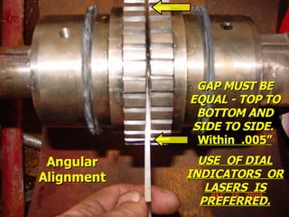
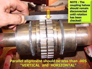
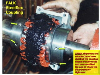
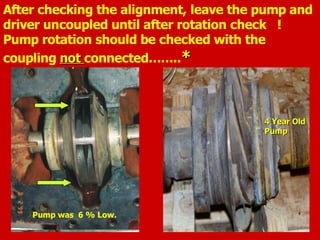
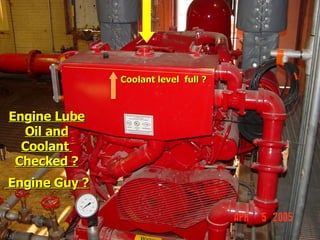
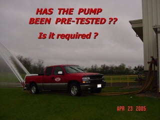
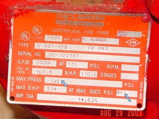
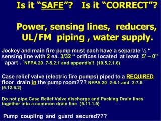
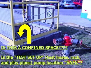
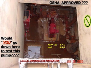
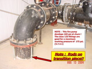
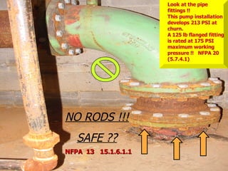
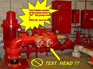
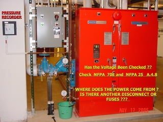
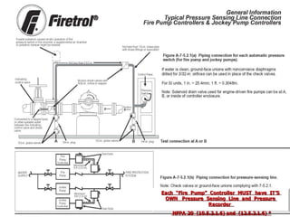
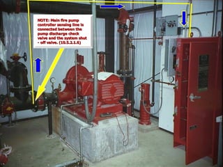
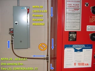
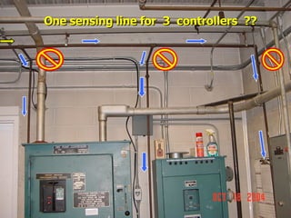
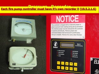
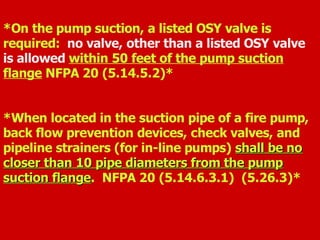
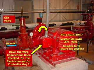
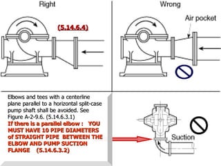
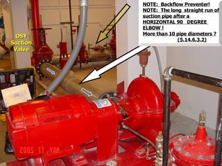
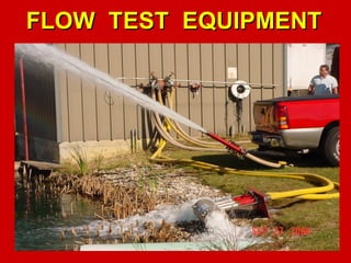
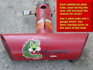
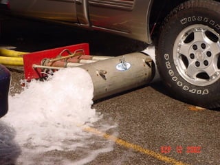
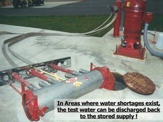
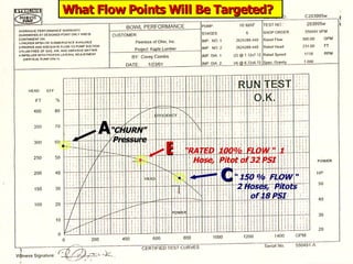
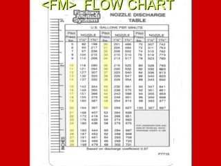
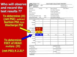
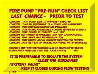
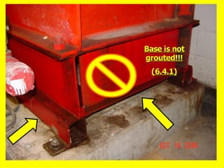
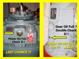
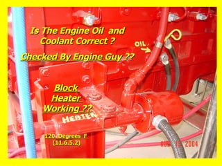
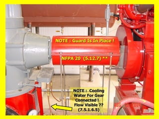
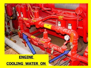
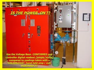
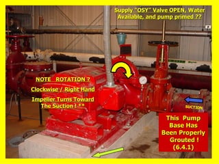
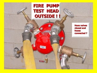
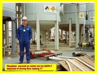
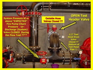
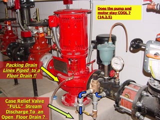
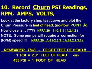
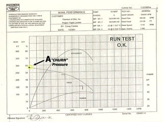
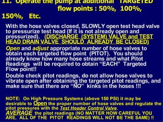
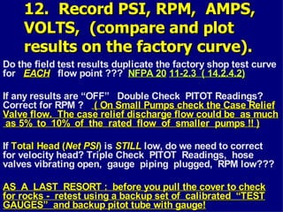
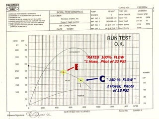
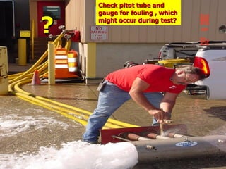
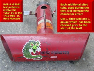
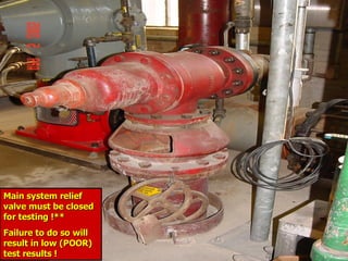
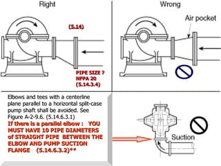
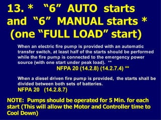
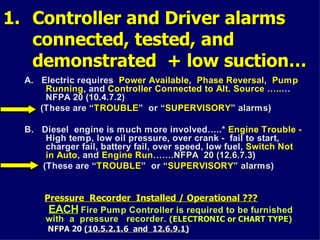
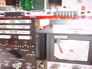
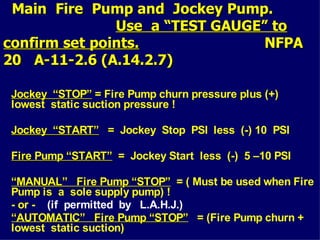
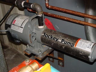
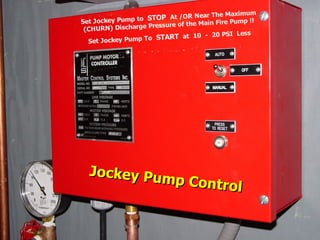
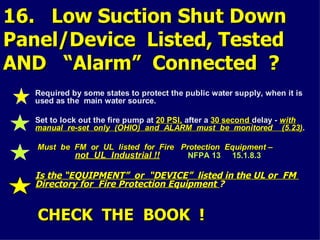
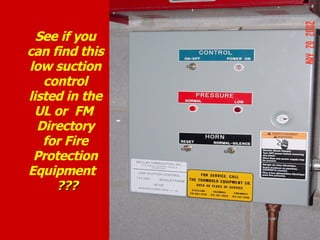
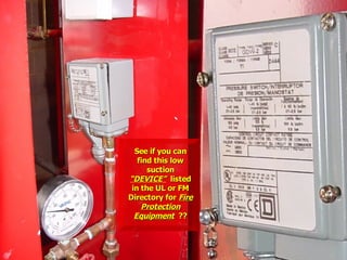
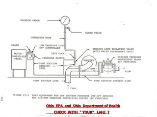
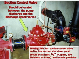
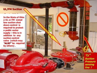
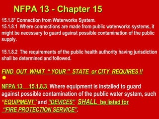
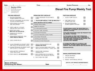
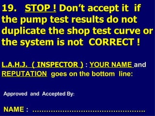
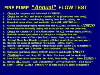
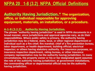
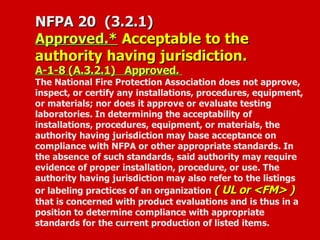
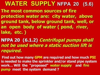
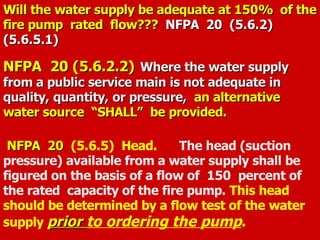
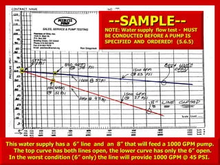
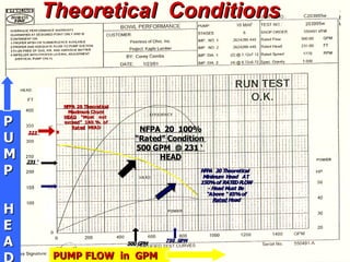
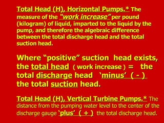
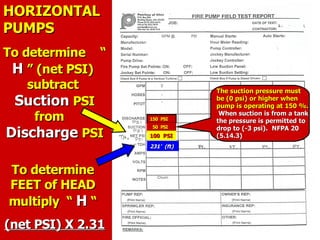
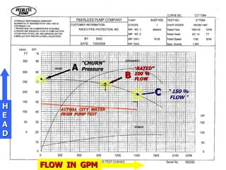
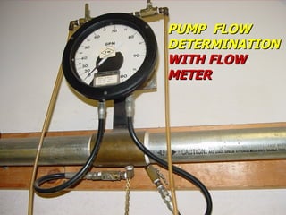
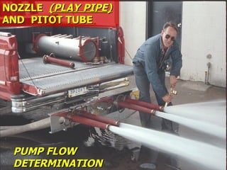
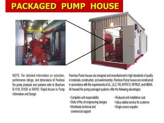
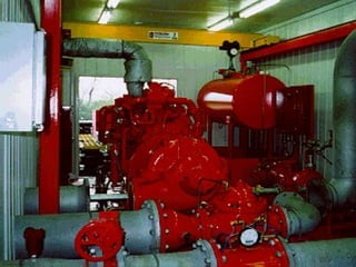
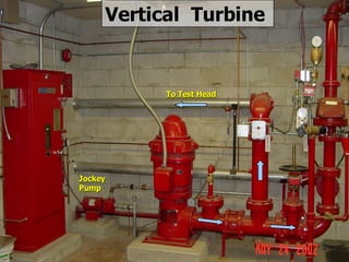
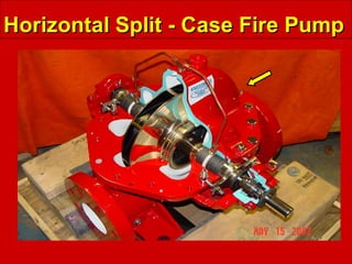
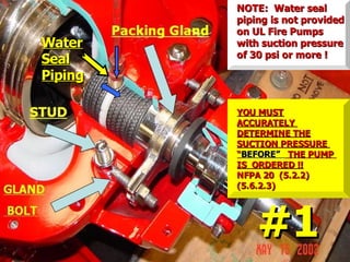
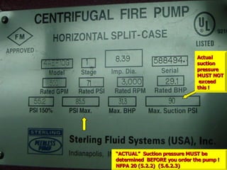
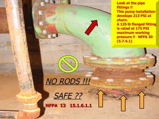
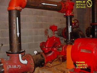
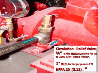
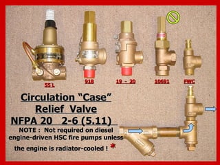
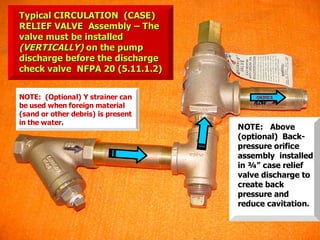
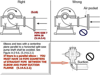
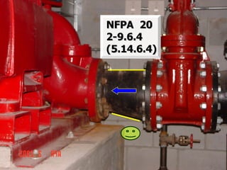
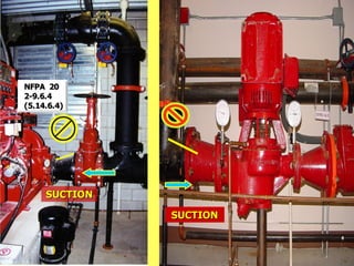
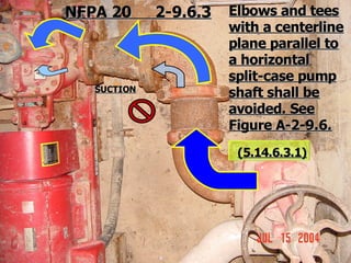
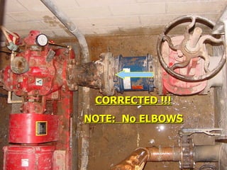
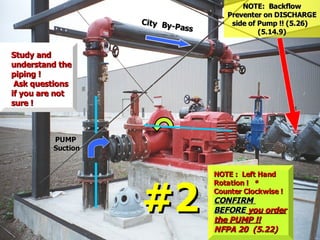
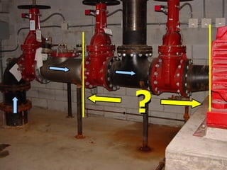
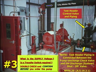
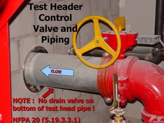
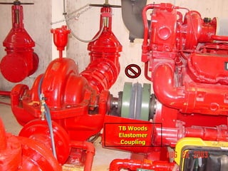
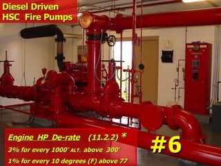
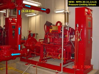
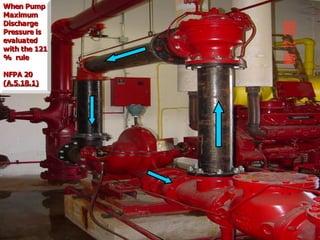
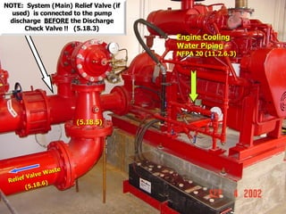
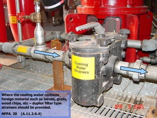
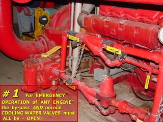
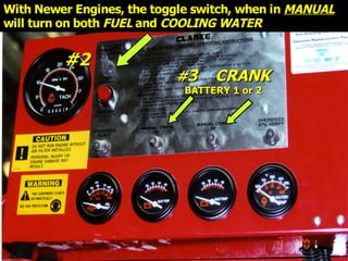
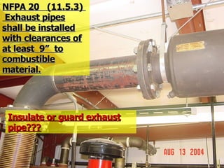
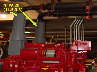
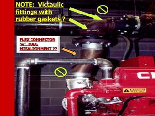
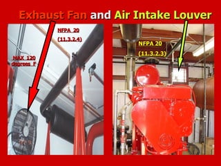
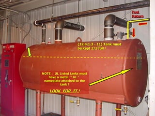
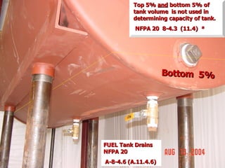
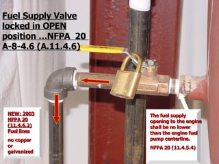
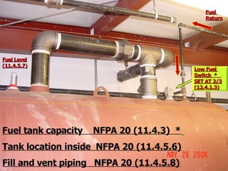
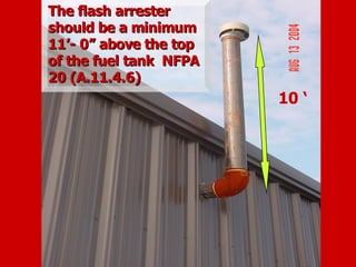
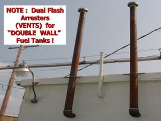
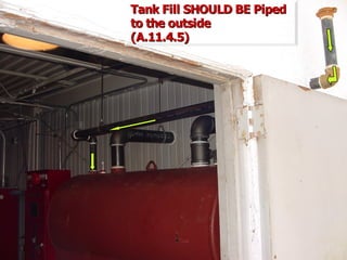
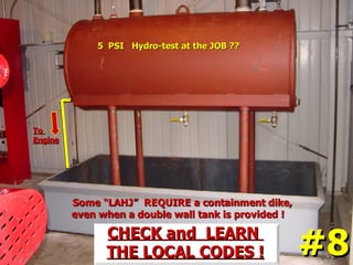
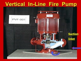
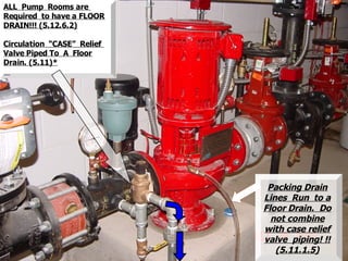
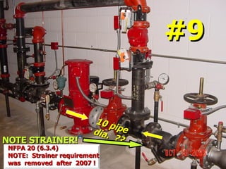
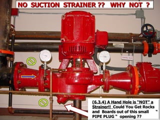
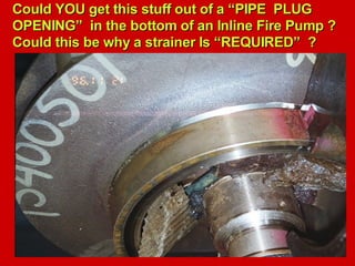
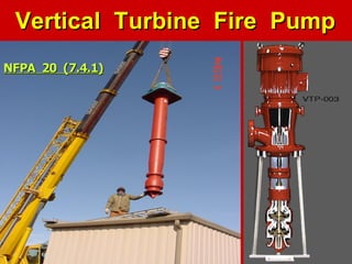
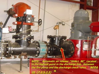
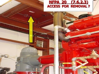
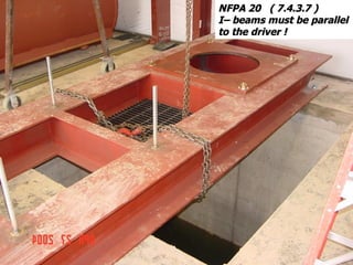
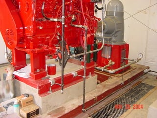
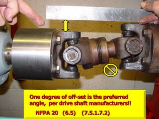
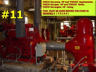
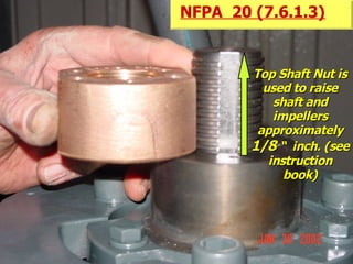
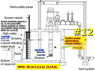
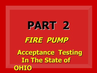
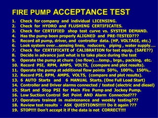
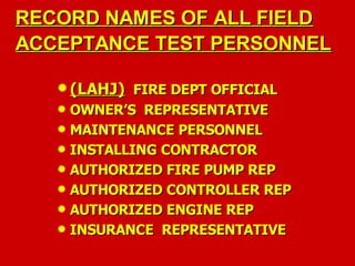
The document outlines definitions and regulations from NFPA 20 regarding fire protection systems, focusing on the authority having jurisdiction, accepted standards for equipment and installations, and water supply requirements for fire pumps. It specifies the need for adequate water supply and pressure to maintain fire protection systems and details the acceptable configurations of pump installations and their components. Additionally, it emphasizes the importance of conducting water supply flow tests before pump specification to ensure proper operational capabilities.


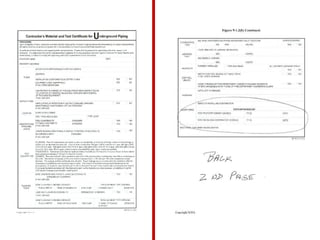
![Table (14.1.1.1[a])
Table (14.1.1.1[a]) Minimum Flush Rates
Minimum Flush Rates.
.
Contractor may have a calculated system
Contractor may have a calculated system
demand which, if greater, will require higher
demand which, if greater, will require higher
flush rates than those listed below.
flush rates than those listed below.
Pipe Size
Pipe Size Flow Rate
Flow Rate
in.
in. mm
mm gpm
gpm L/min
L/min
4
4 102
102 590
590 2,233
2,233
6
6 152
152 1,360
1,360 5,148
5,148
8
8 203
203 2,350
2,350 8,895
8,895
10
10 254
254 3,670
3,670 13,891
13,891
12
12 305
305 5,290
5,290 20,023
20,023
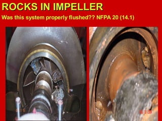
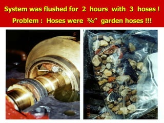
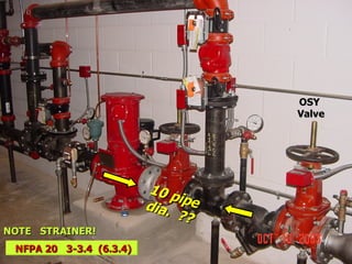
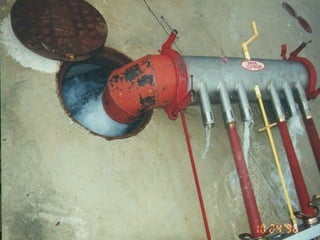
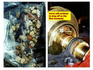
NFPA 20 (14.1.1.1) FLUSHING
NFPA 20 (14.1.1.1) FLUSHING](https://image.slidesharecdn.com/firepumptutorial-240530183554-6744ac79/85/Fire-Pump-Tutorial-as-per-NFPA-20-standard-117-320.jpg)