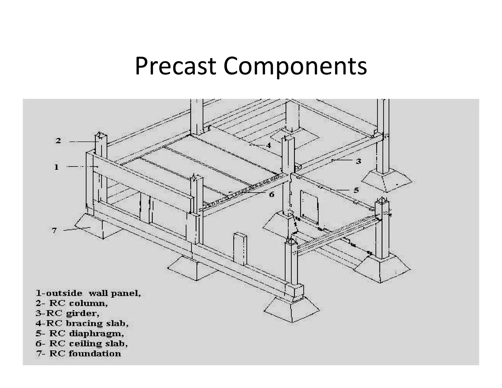
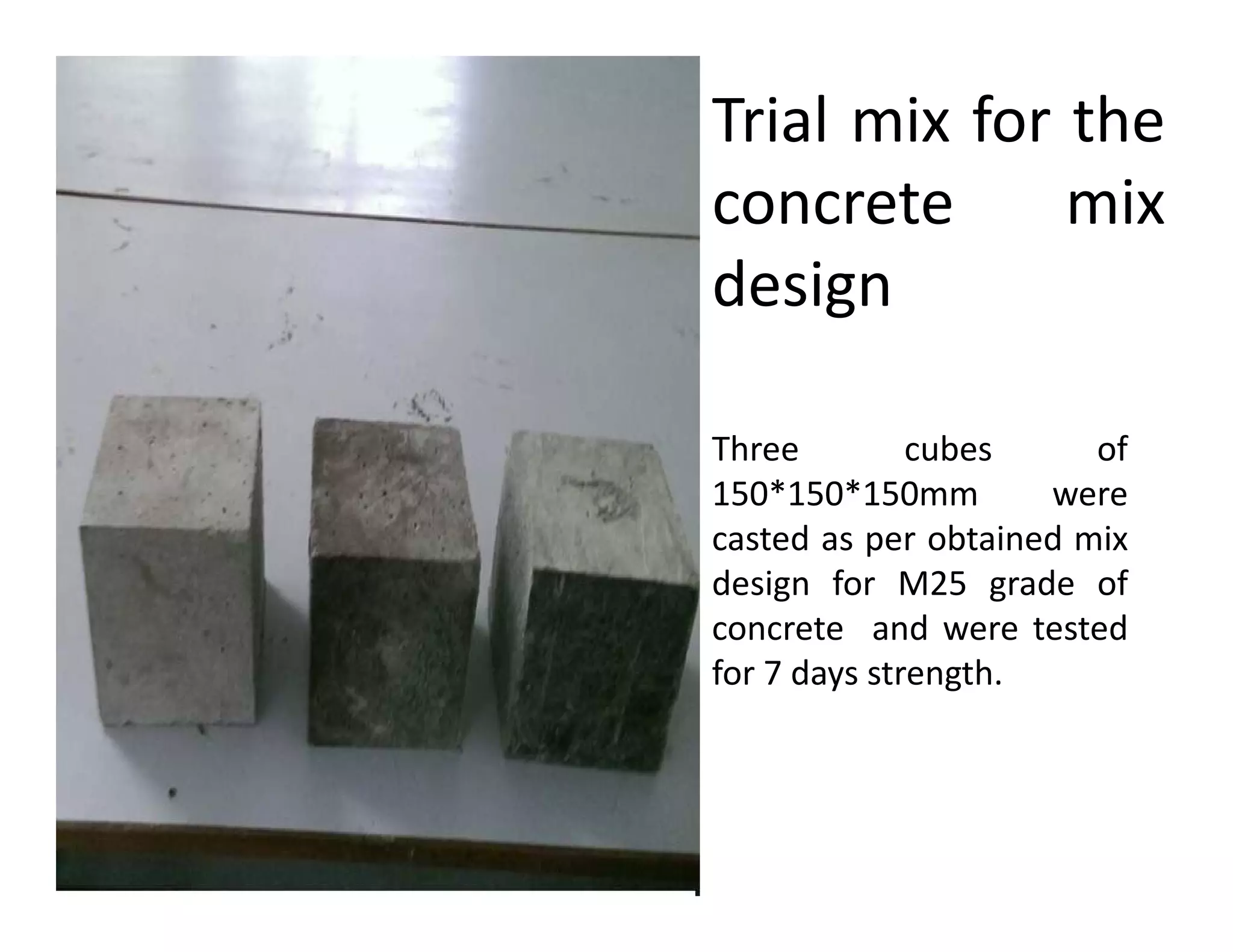
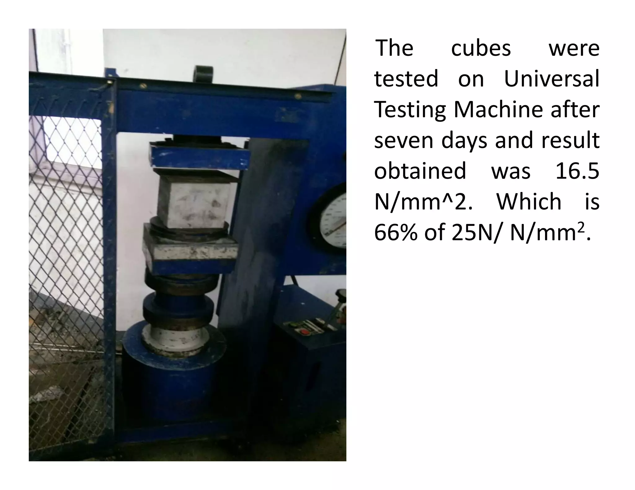
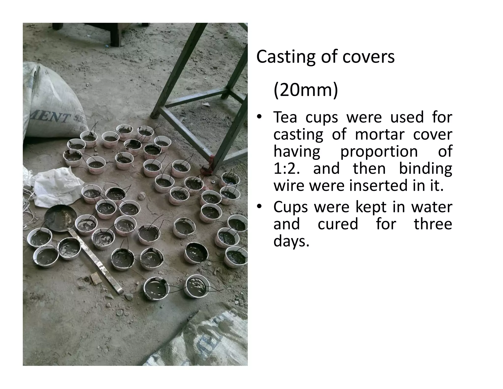
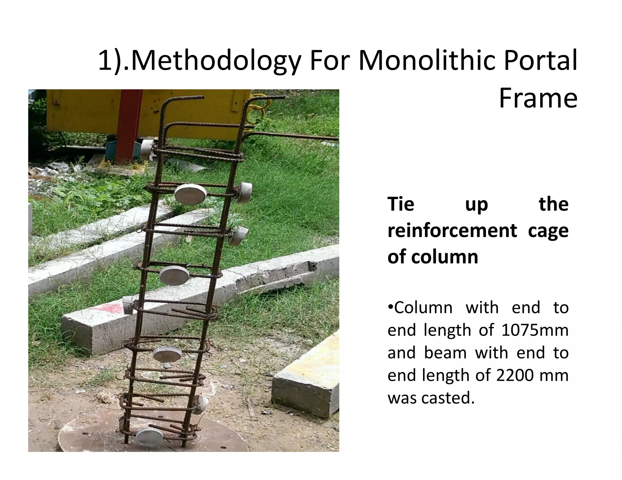
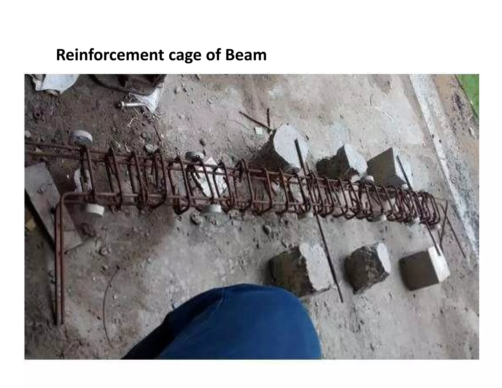
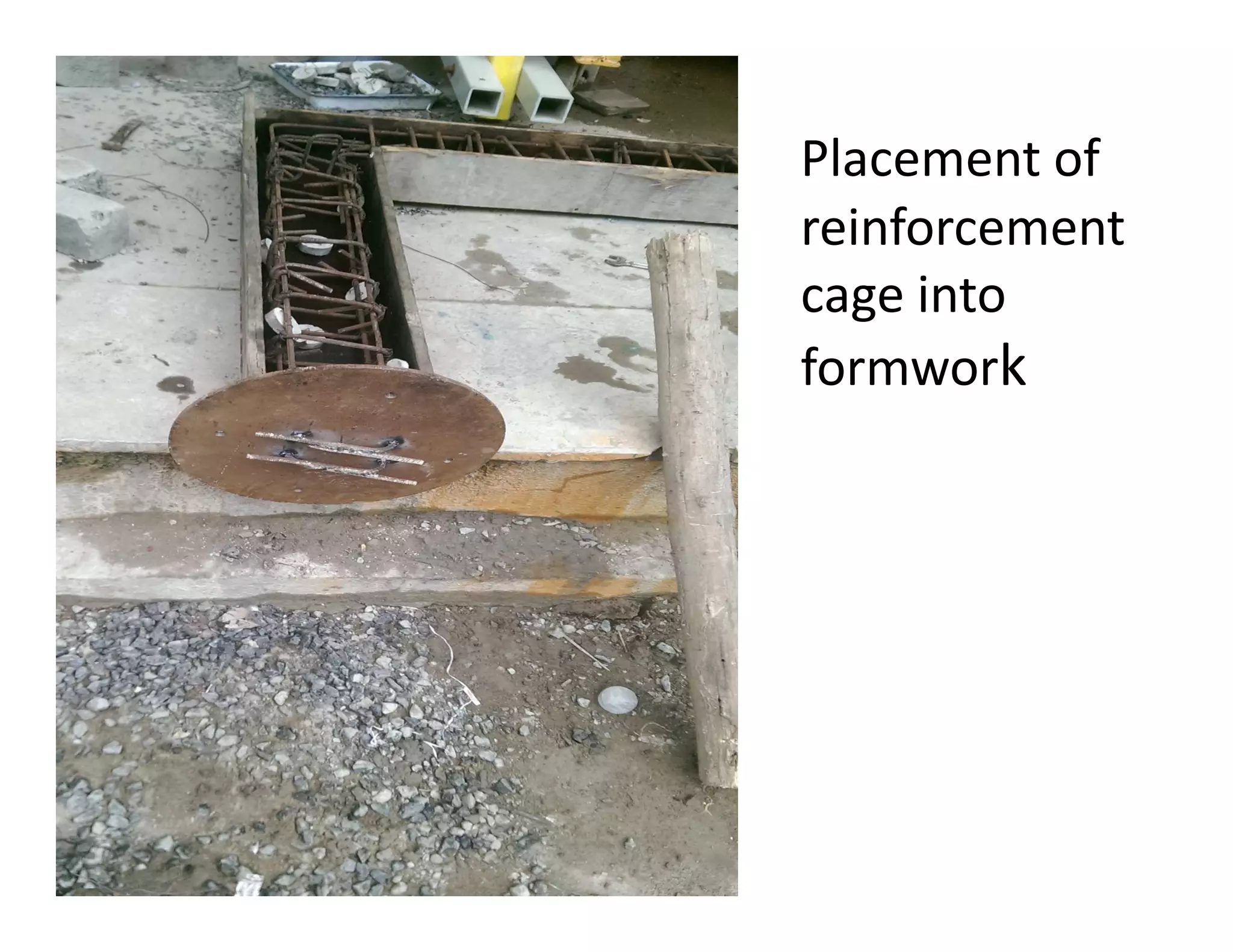
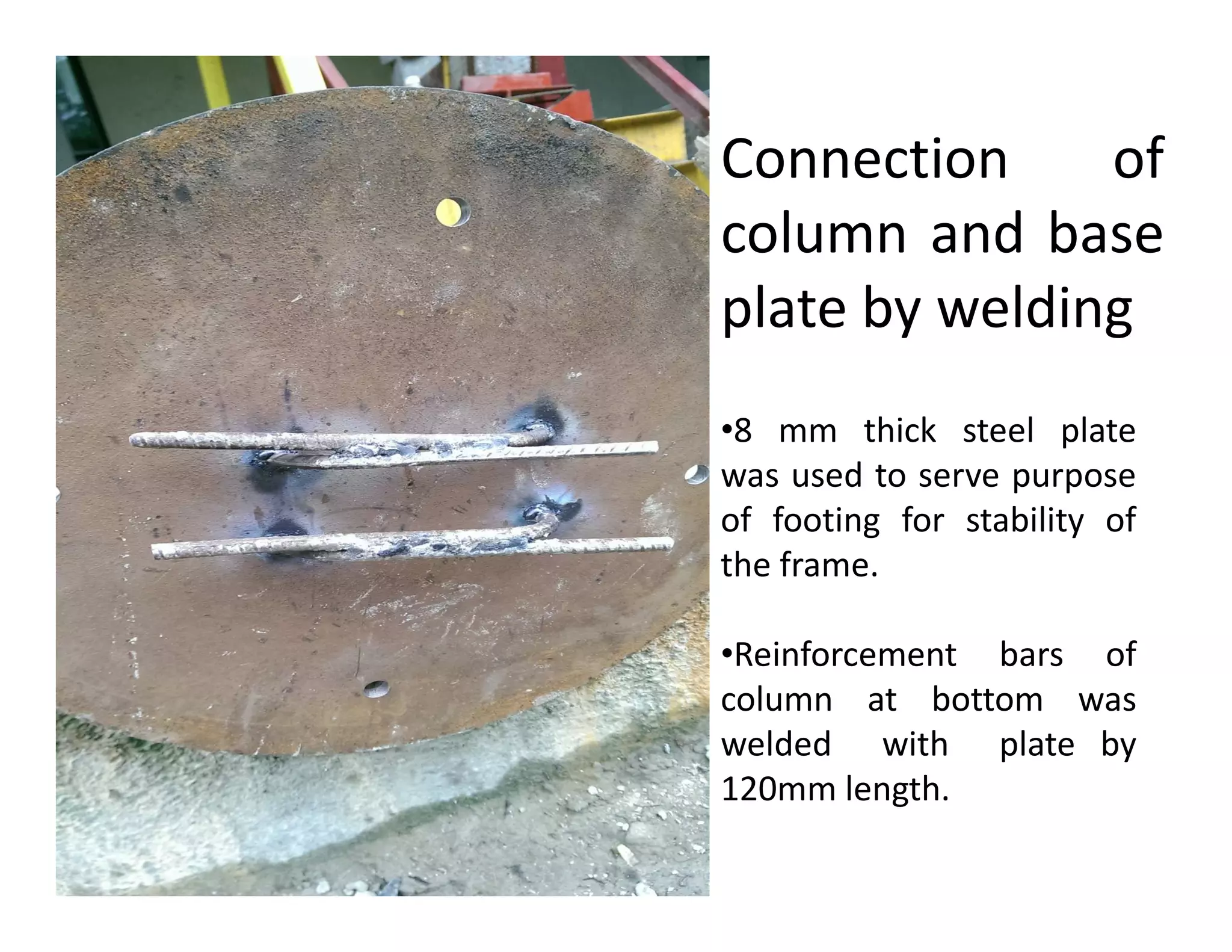
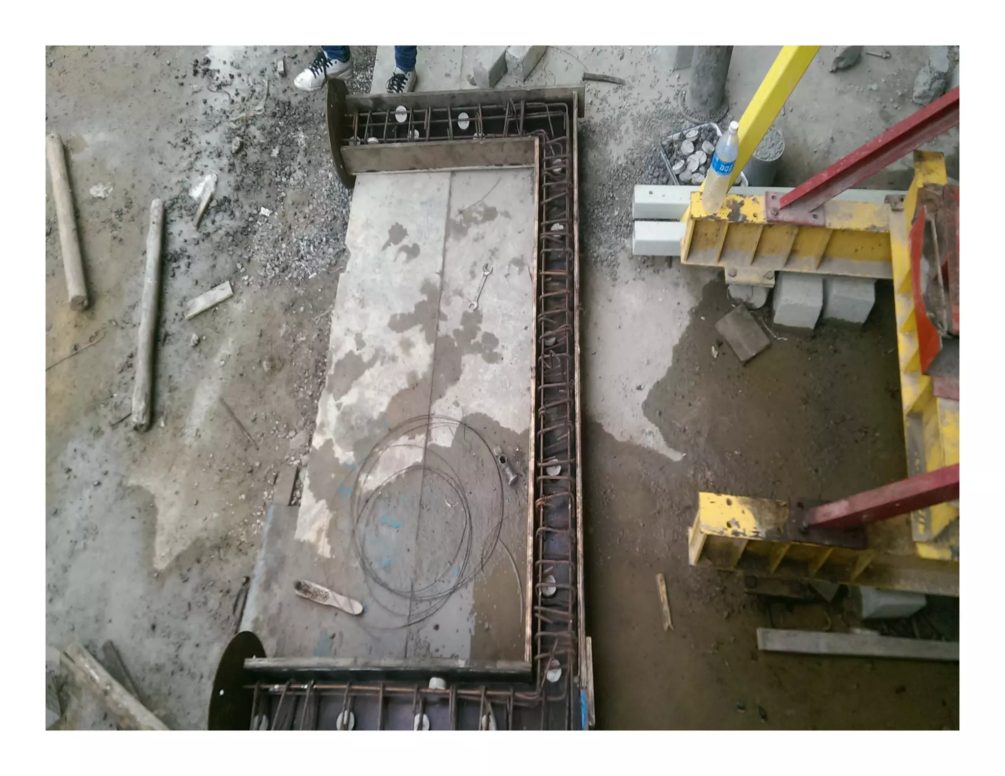
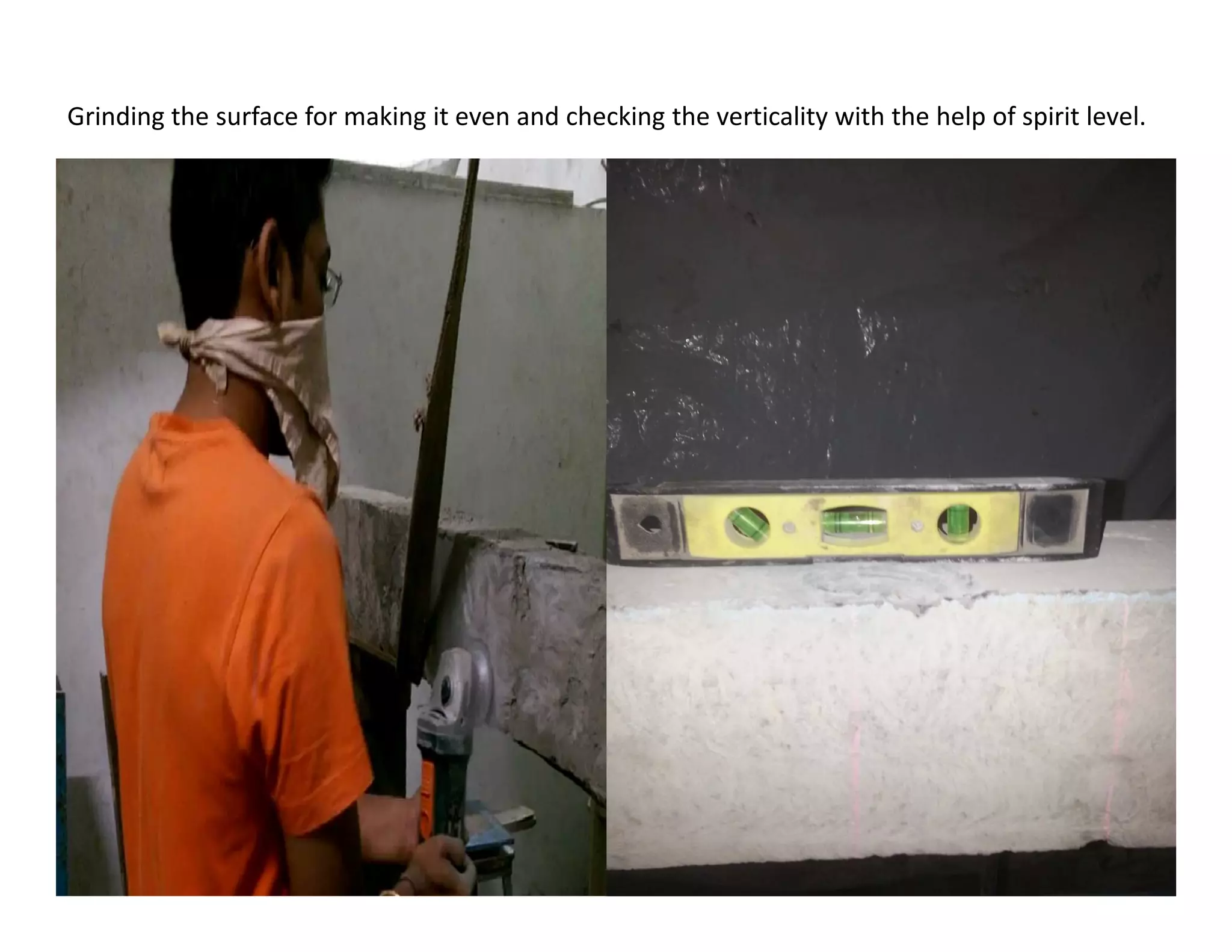
Download as PDF, PPTX


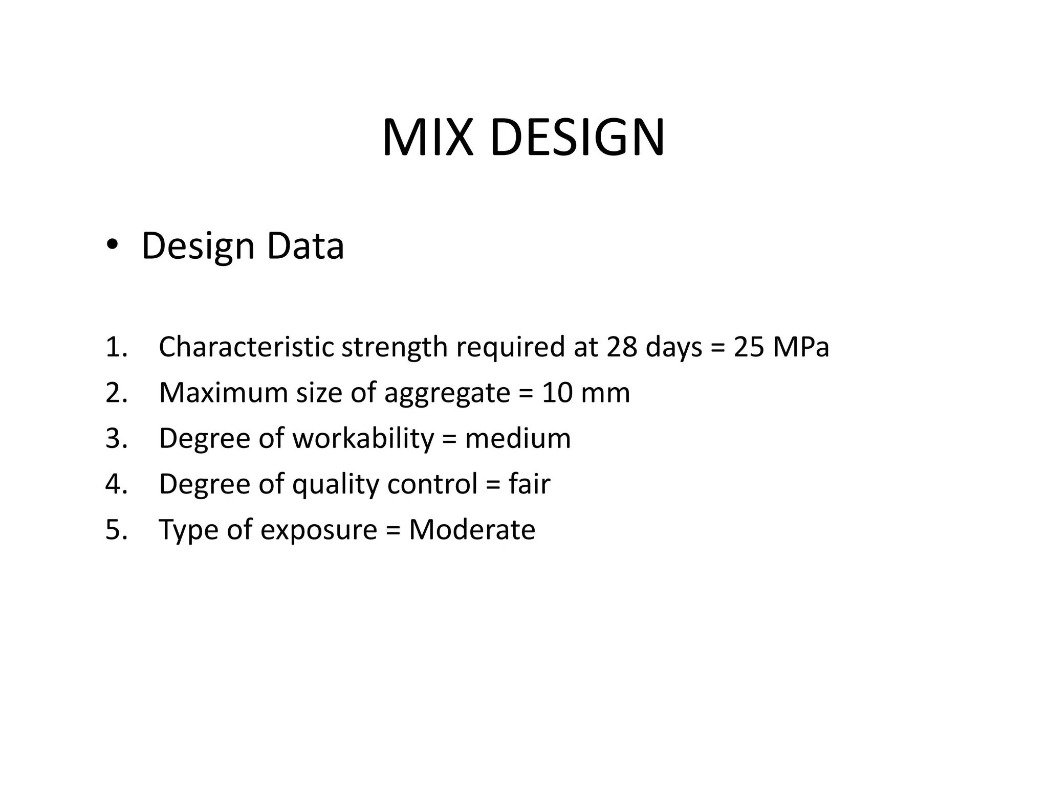
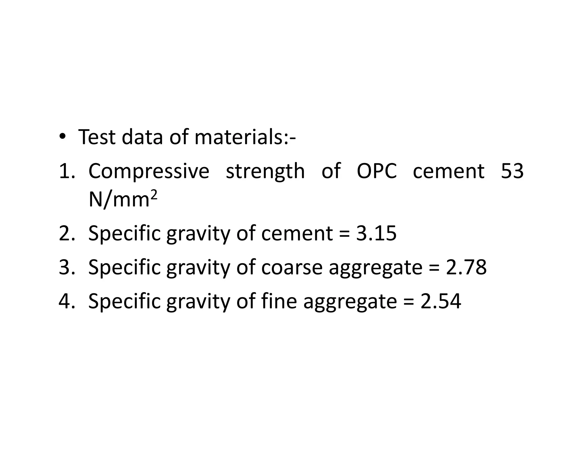
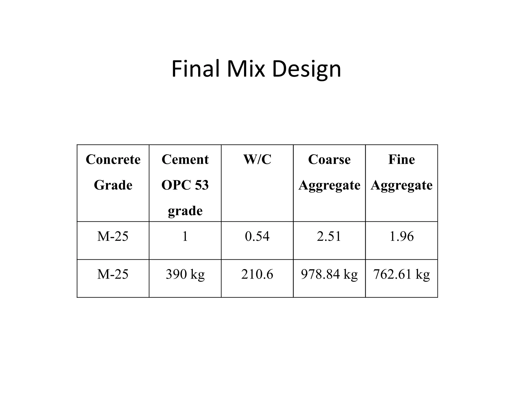
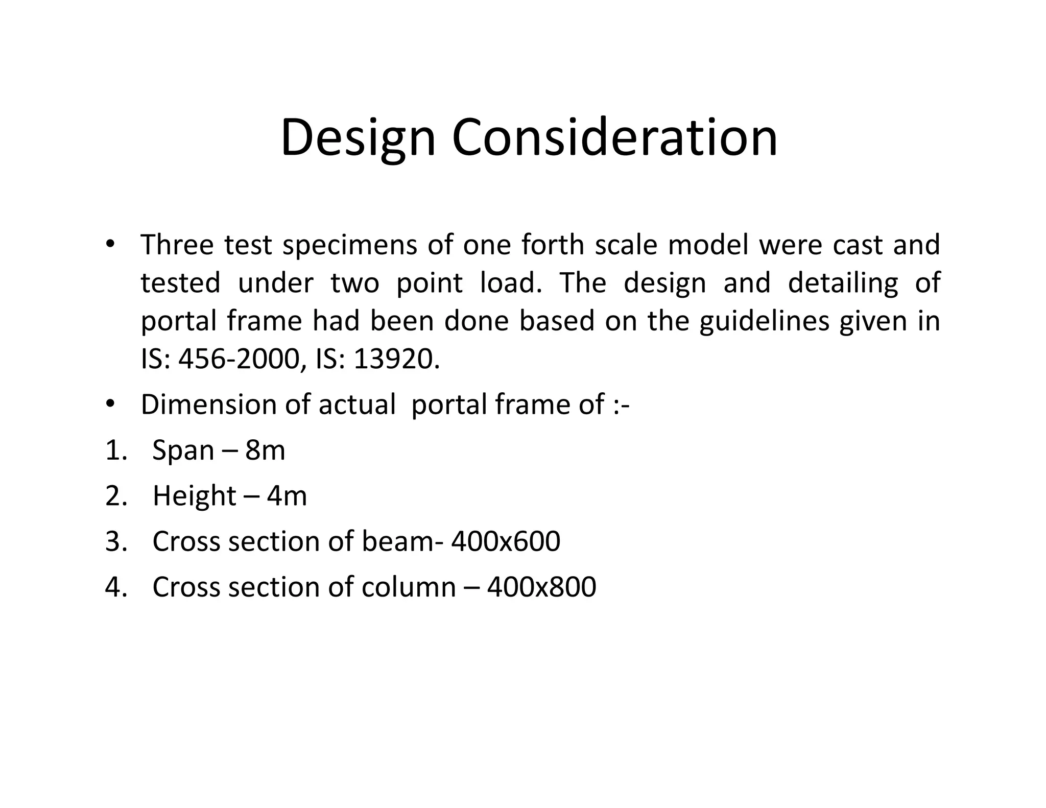
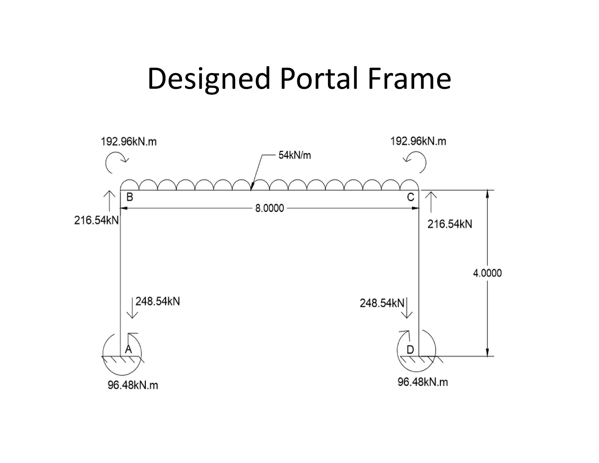
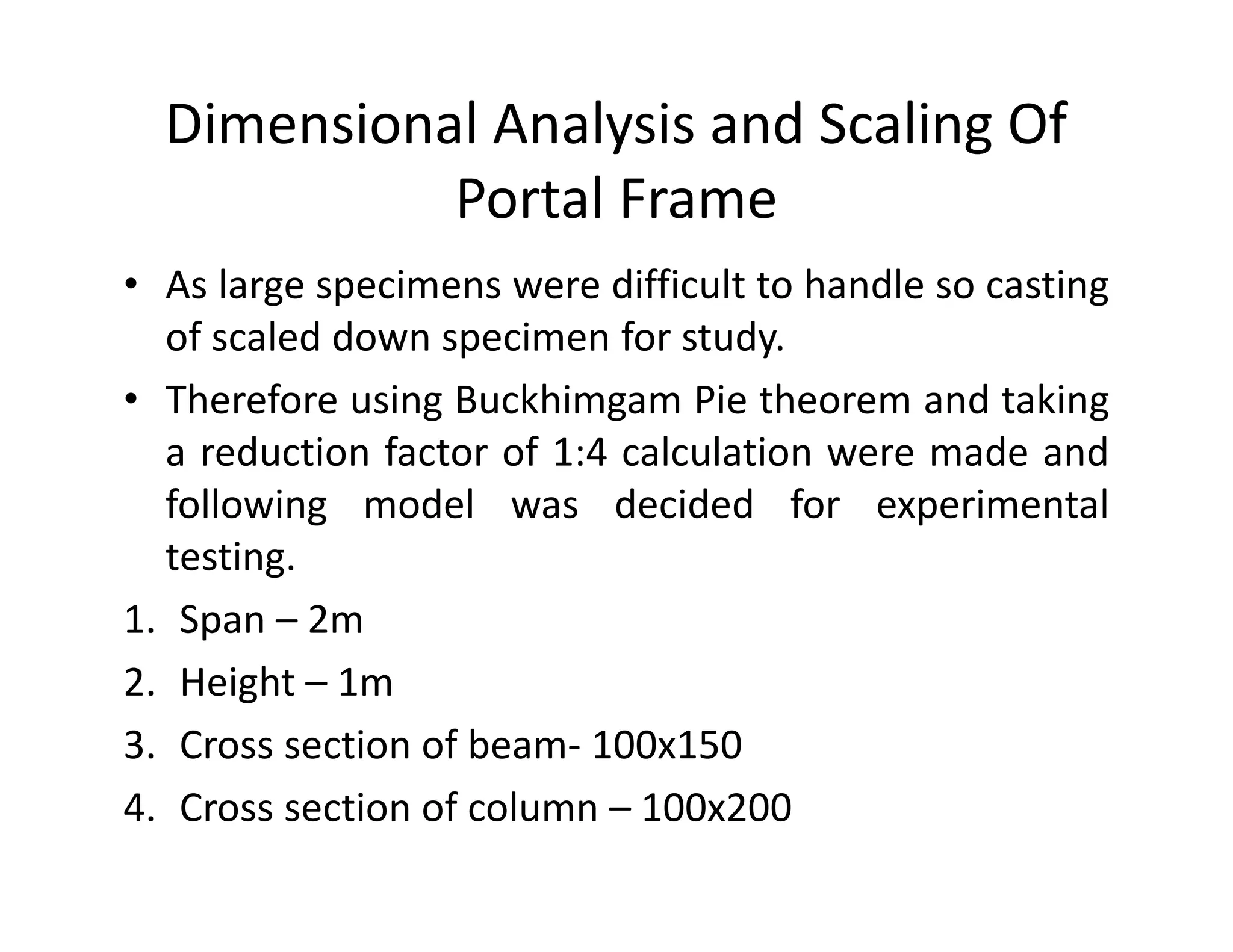
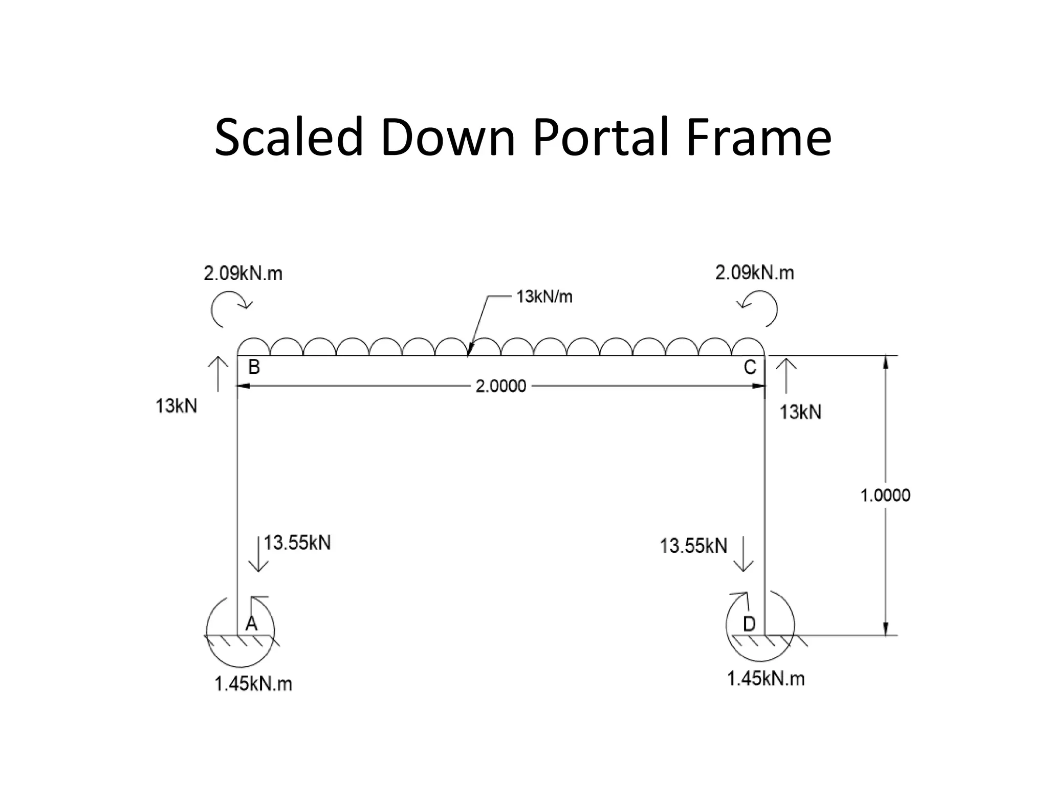
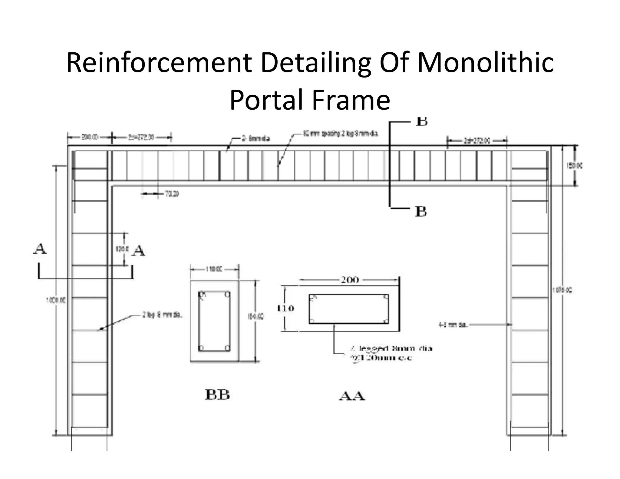


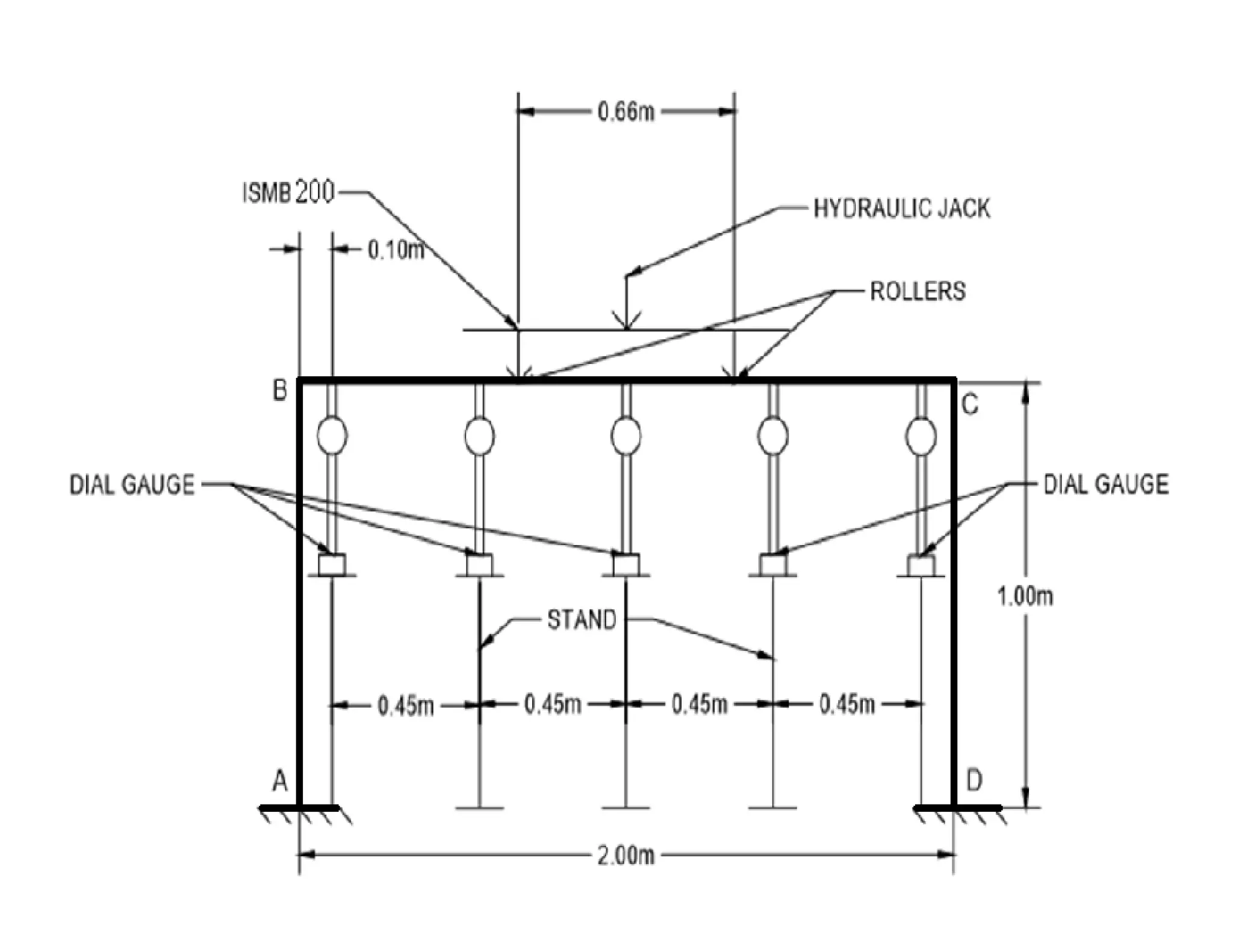
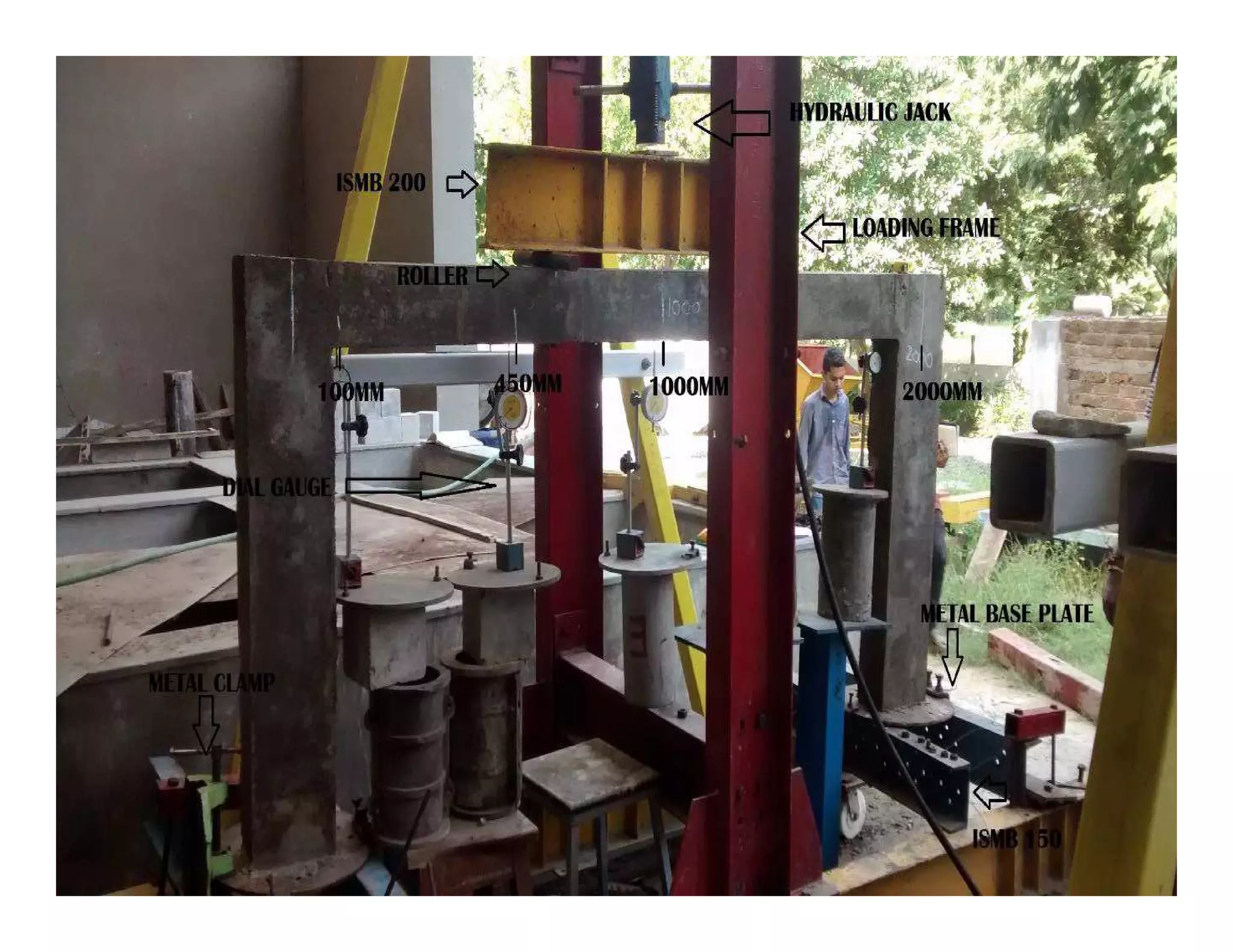
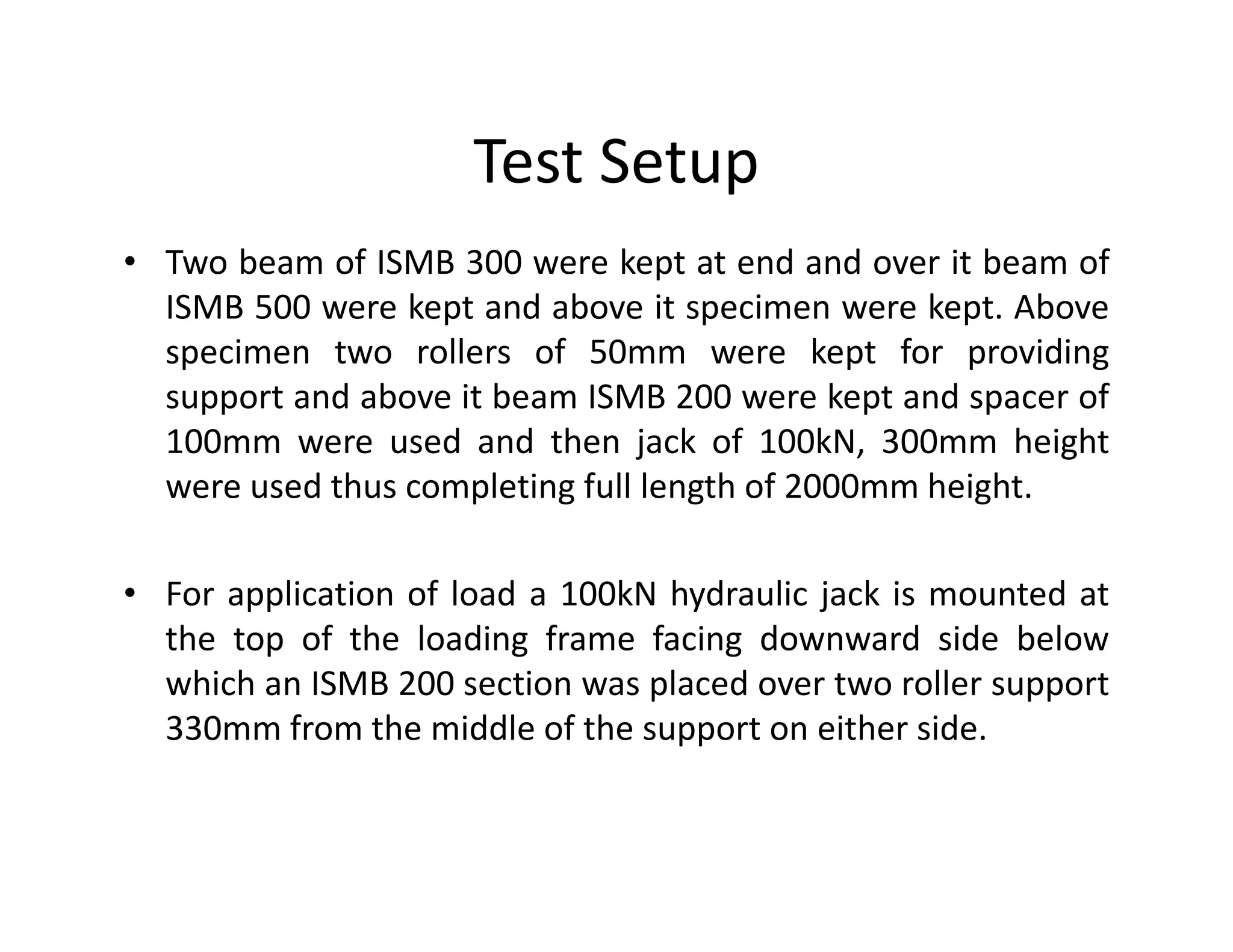
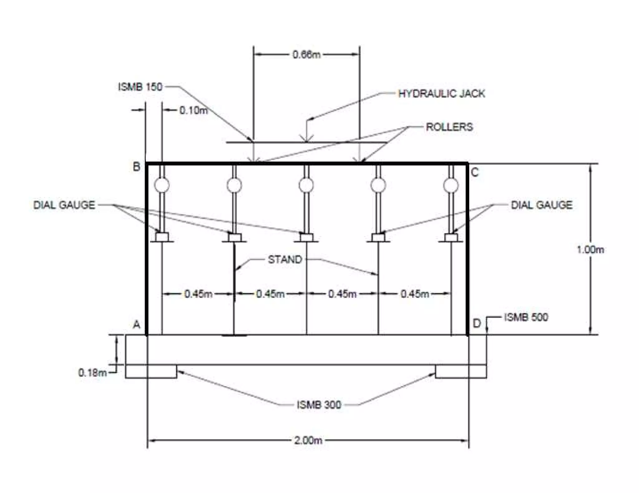
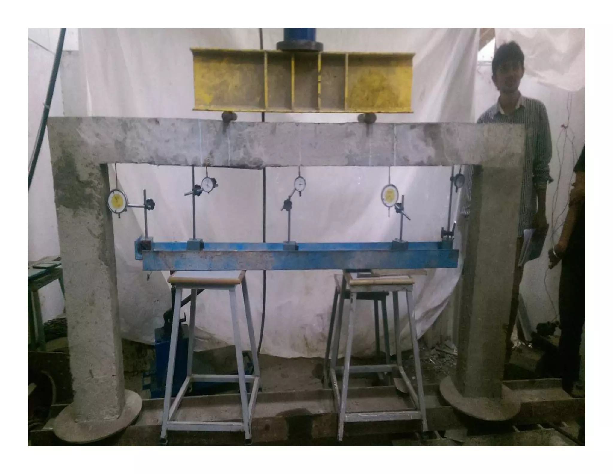
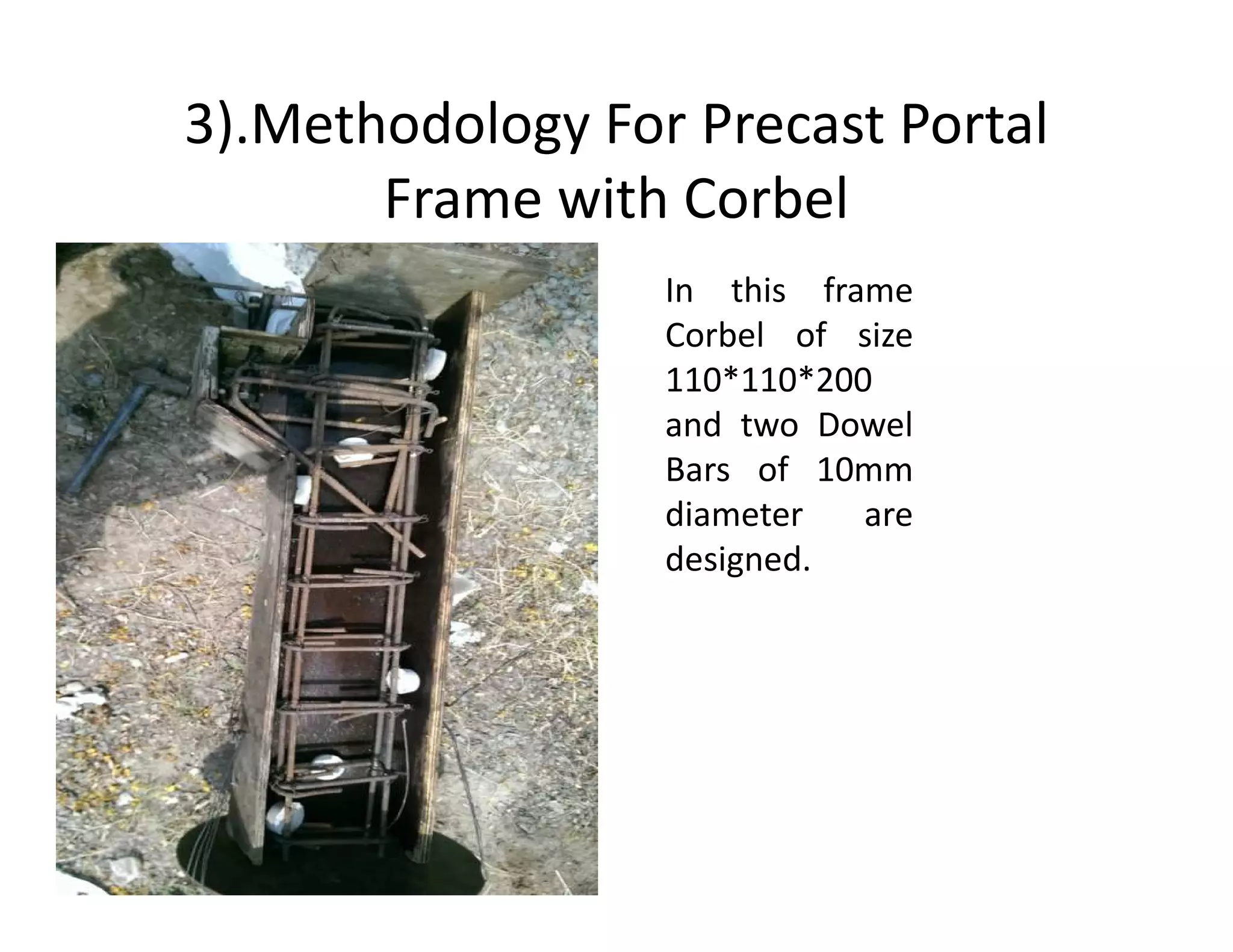
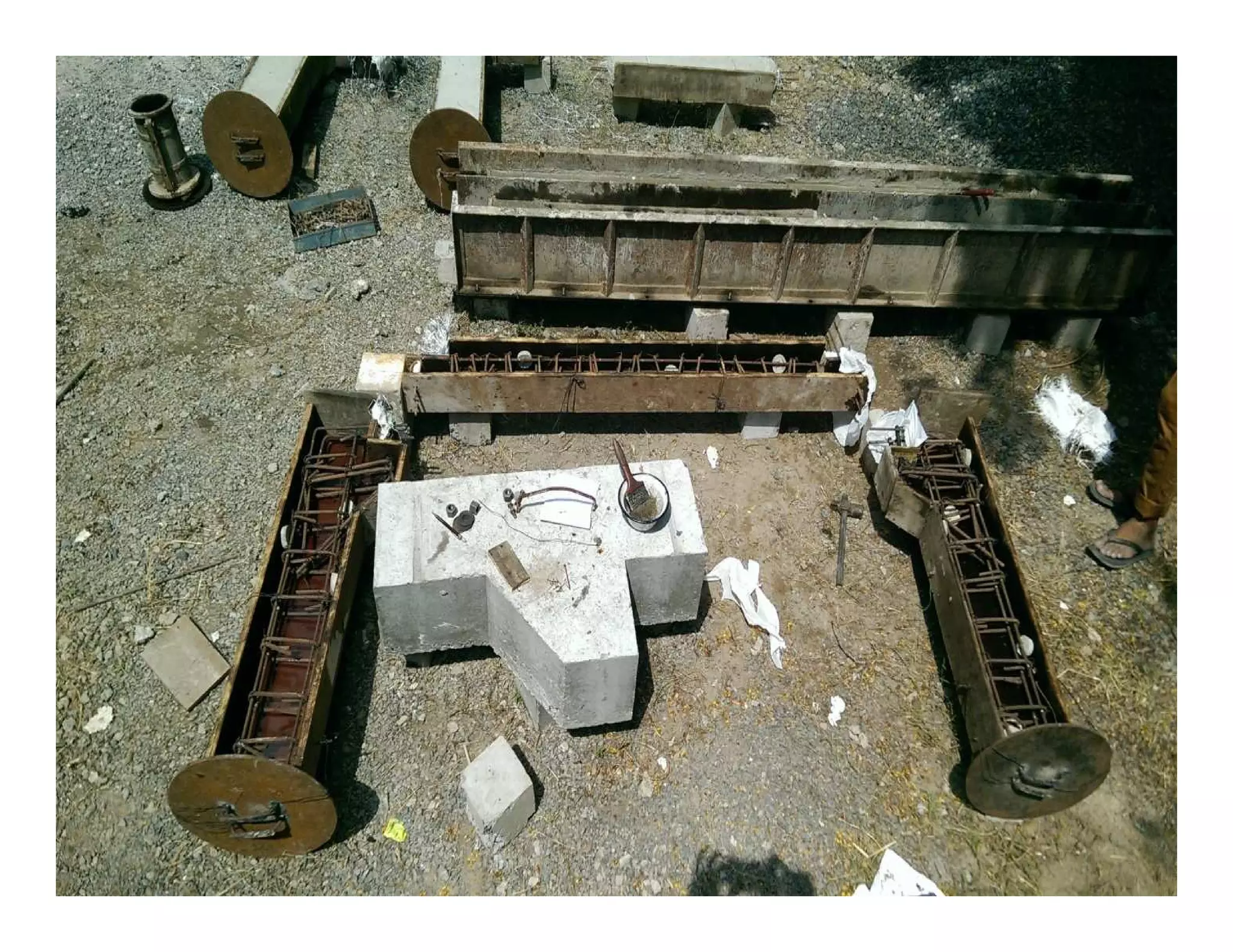
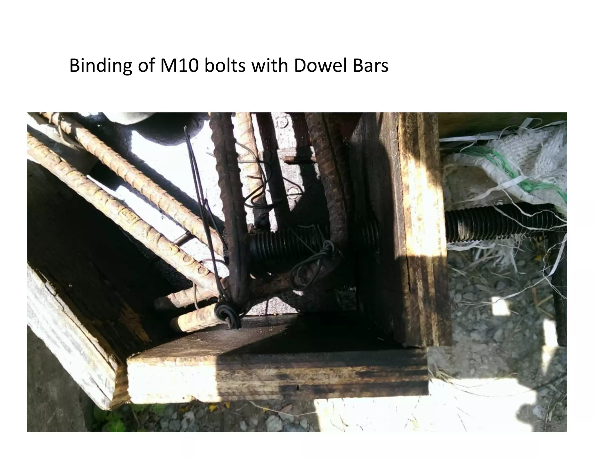
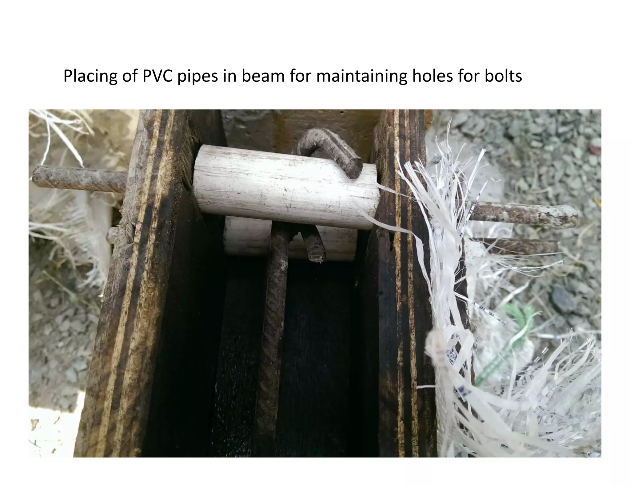
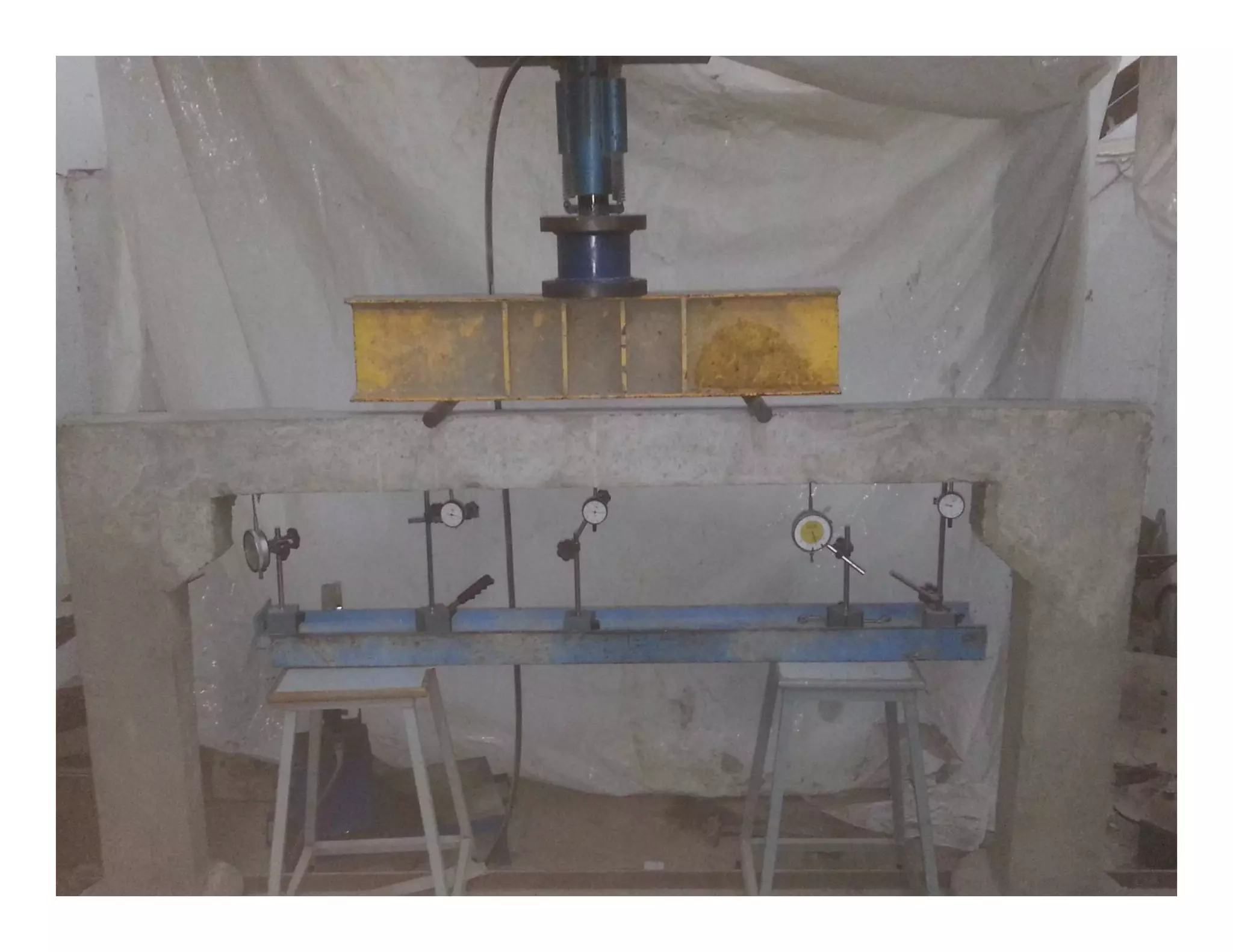

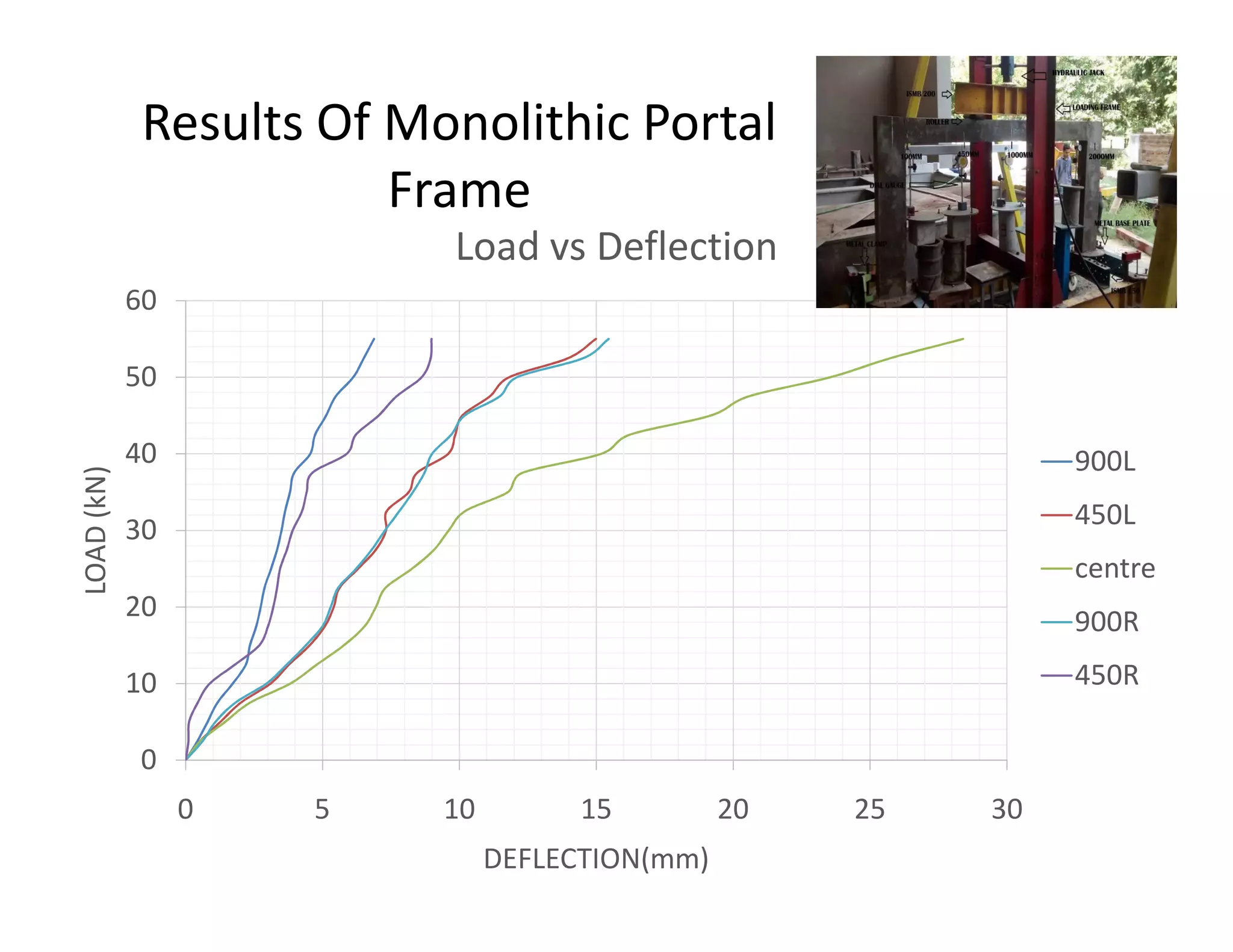
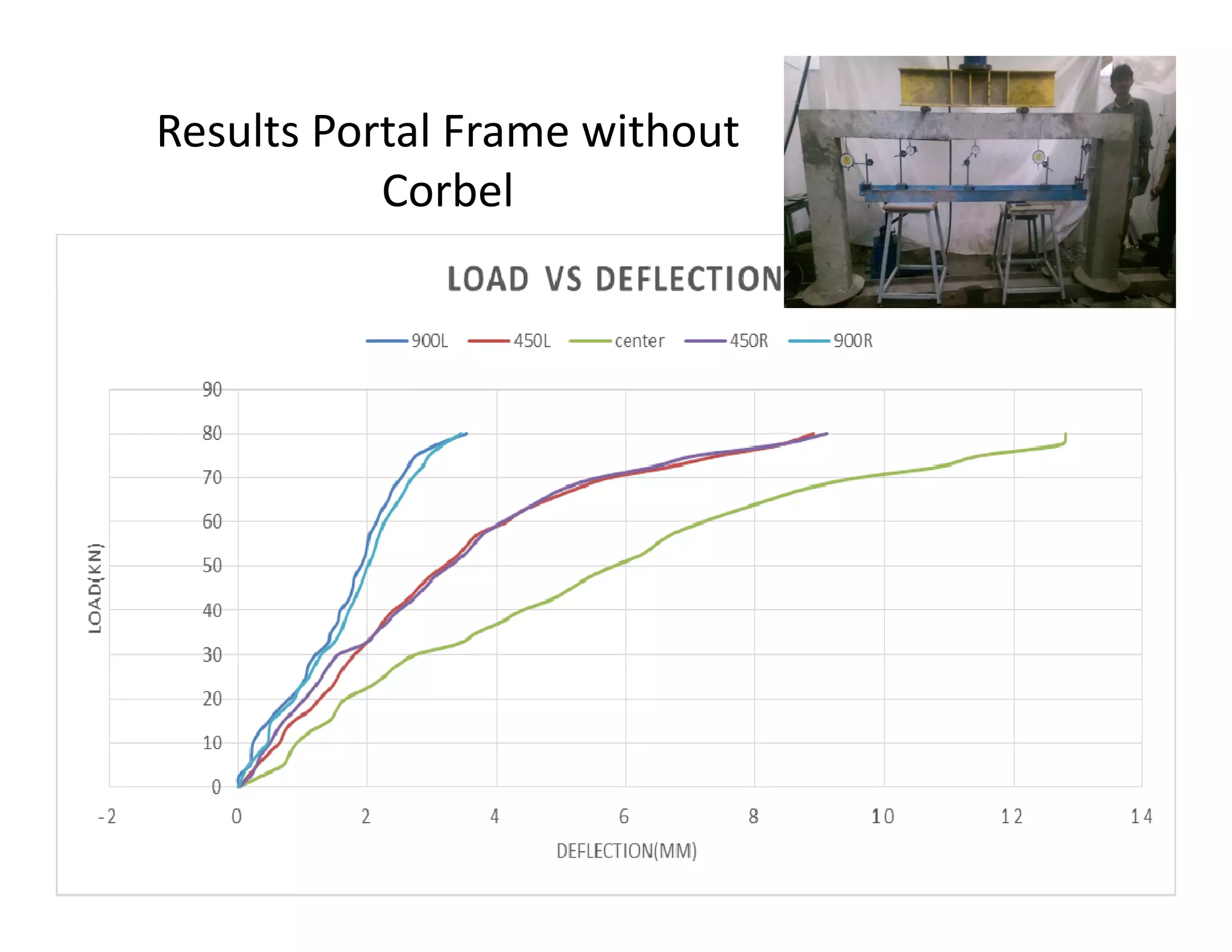
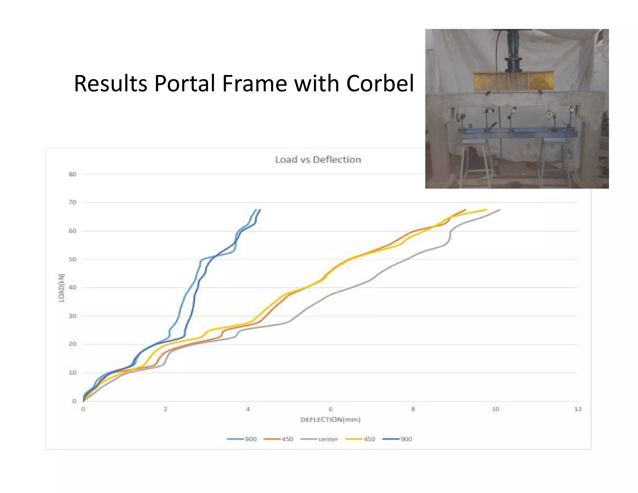
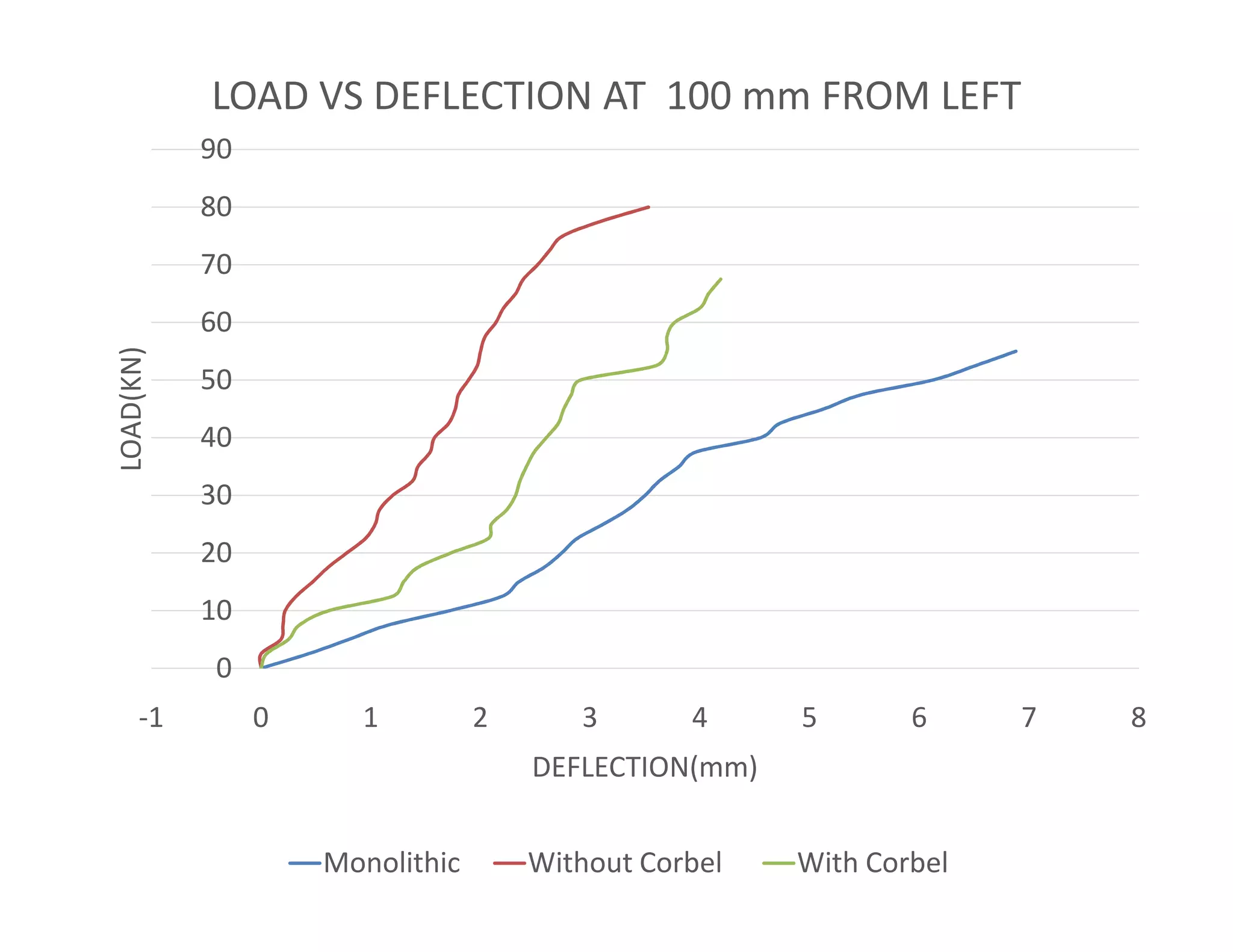
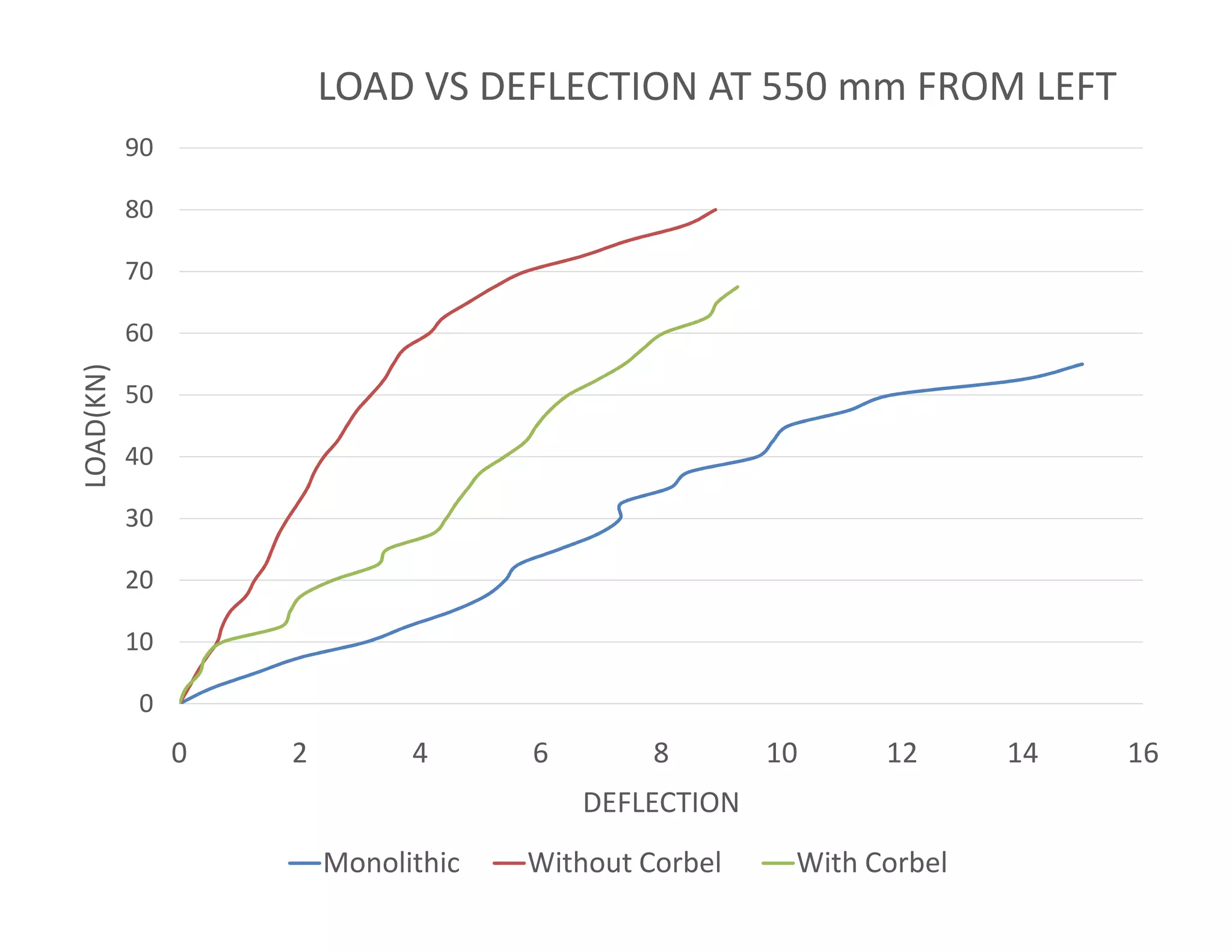
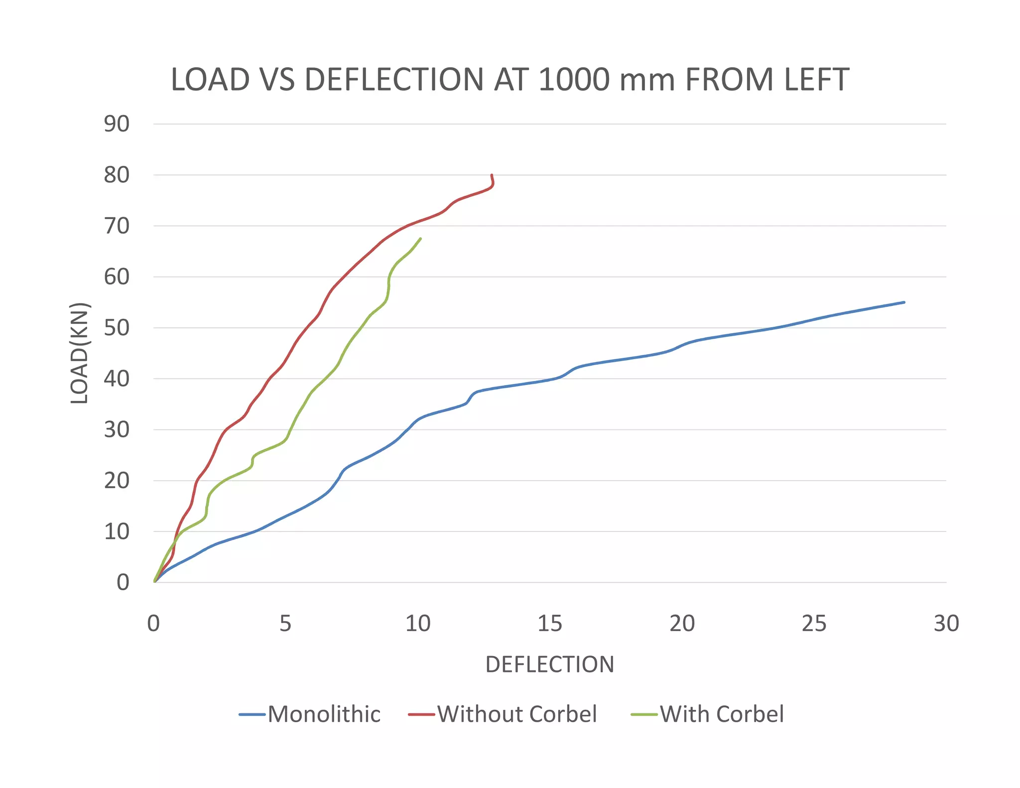
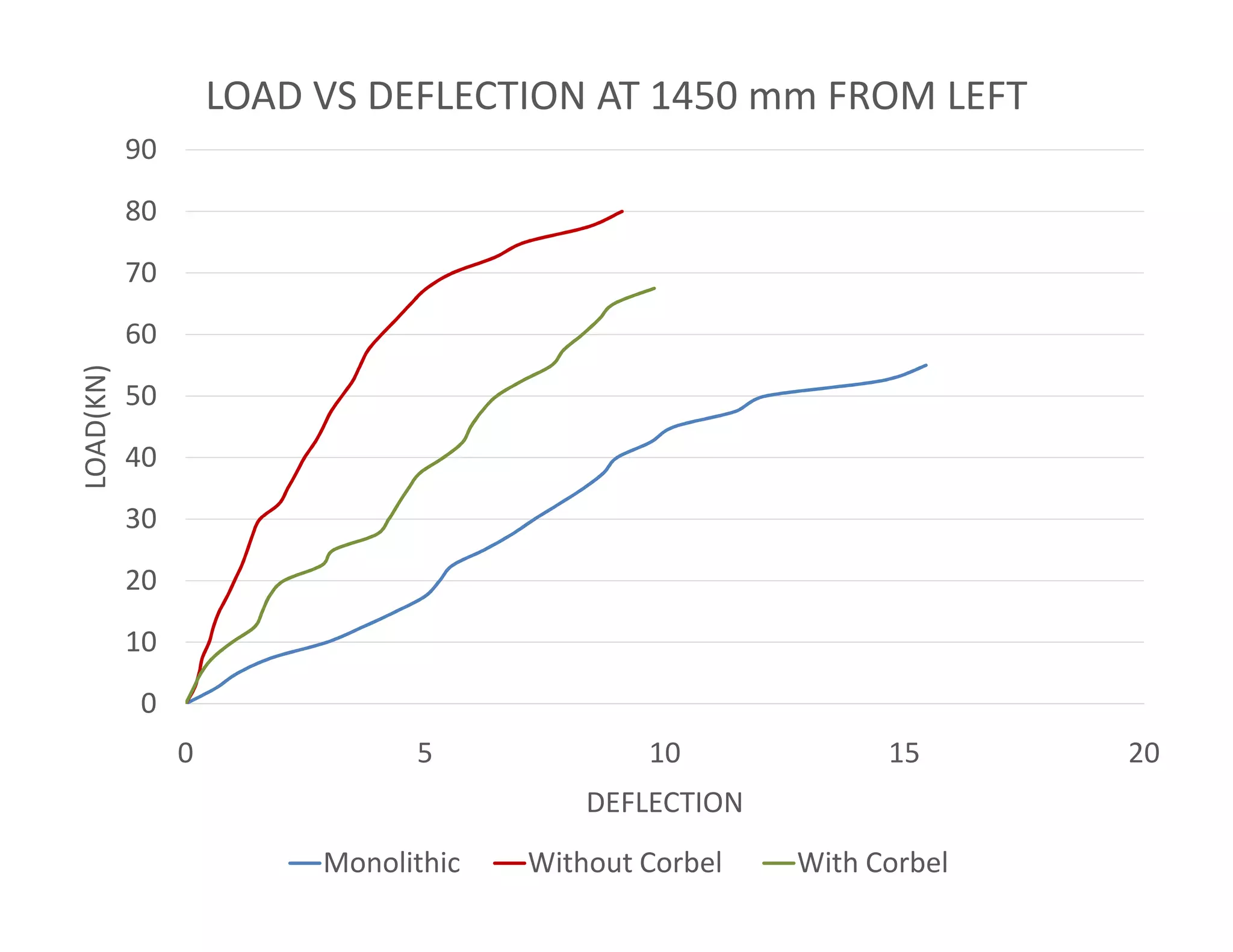
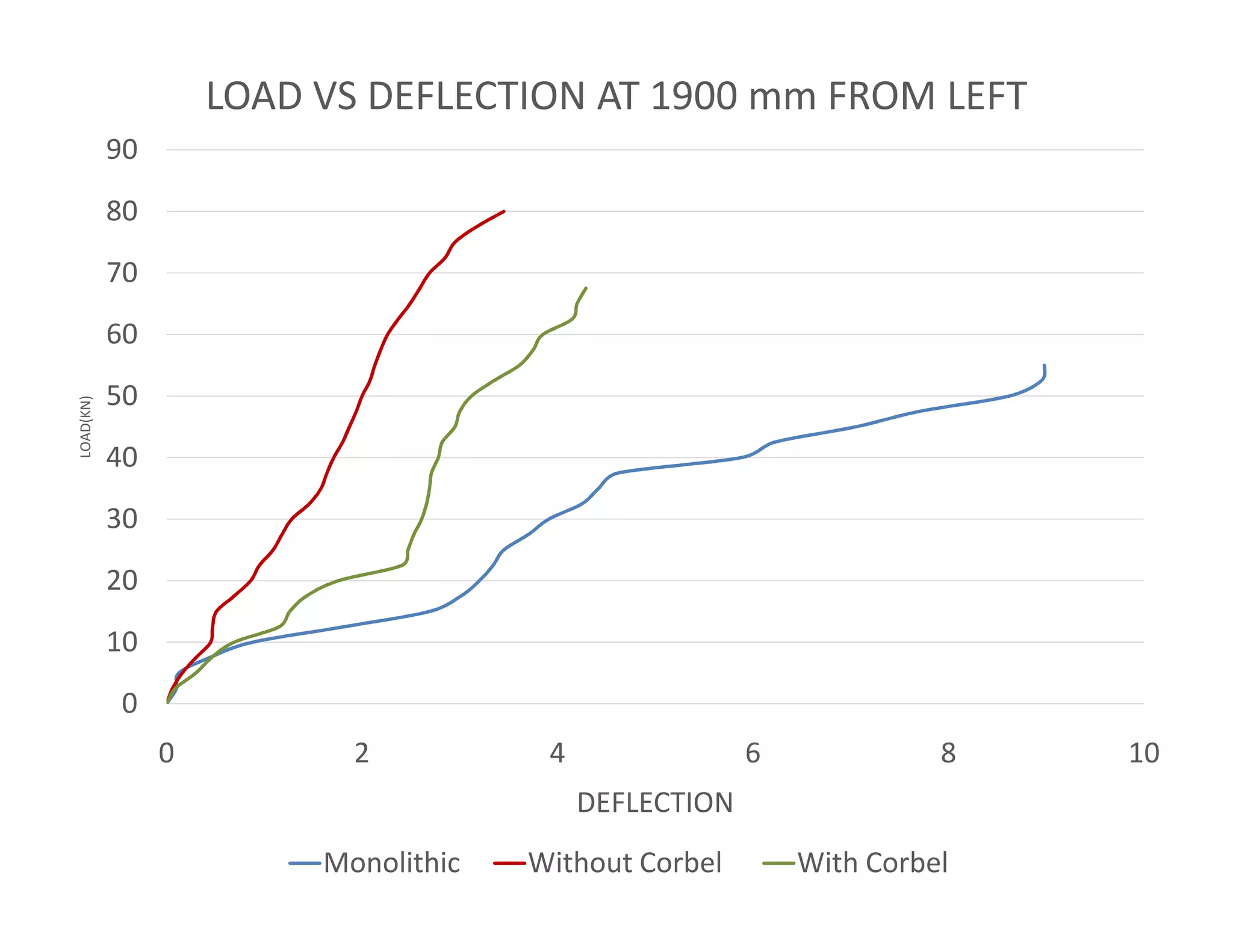
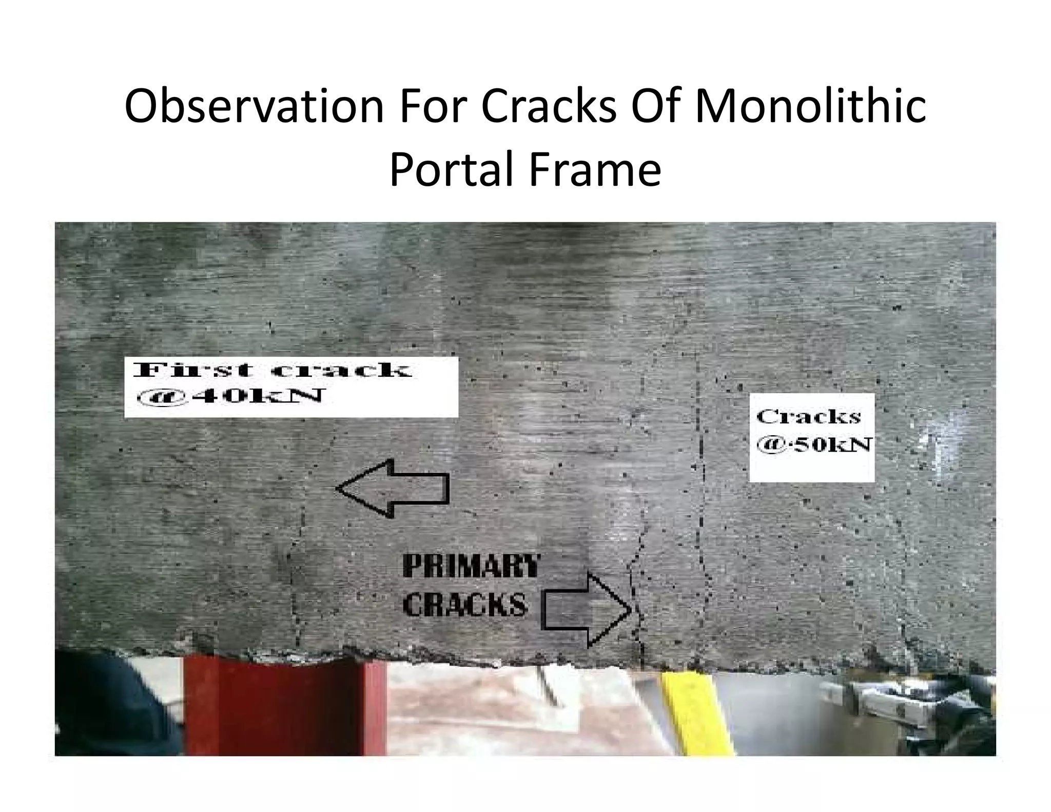
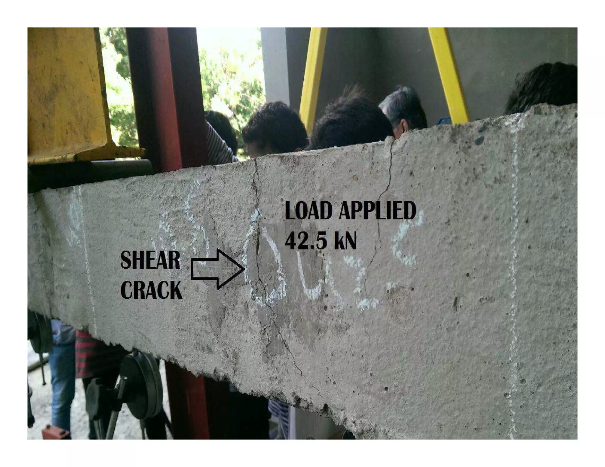
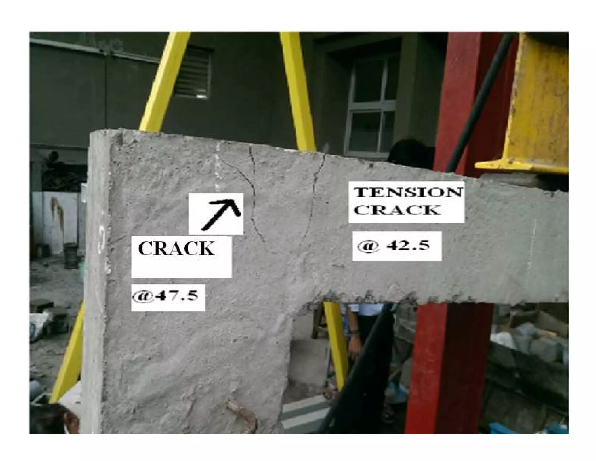
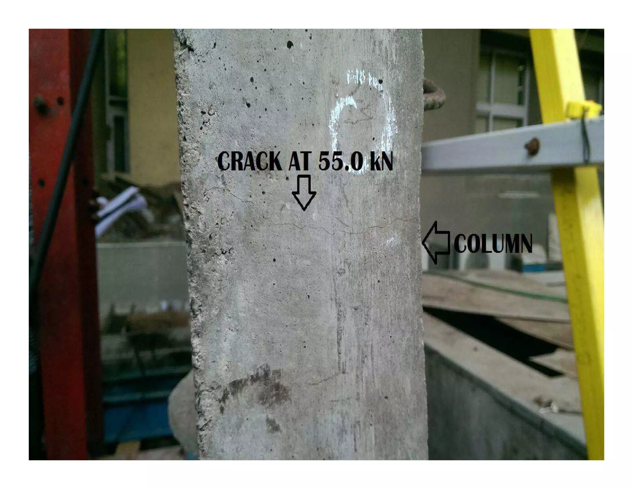
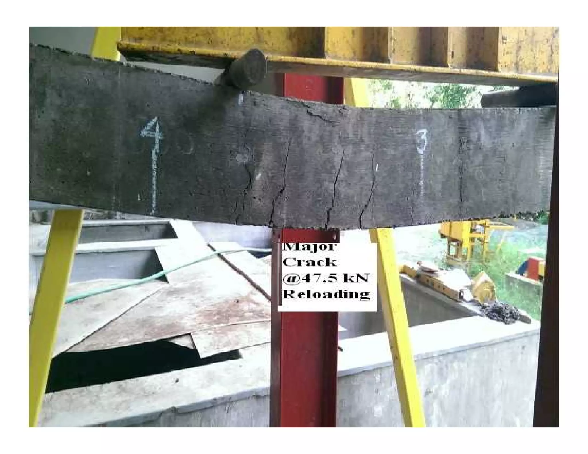
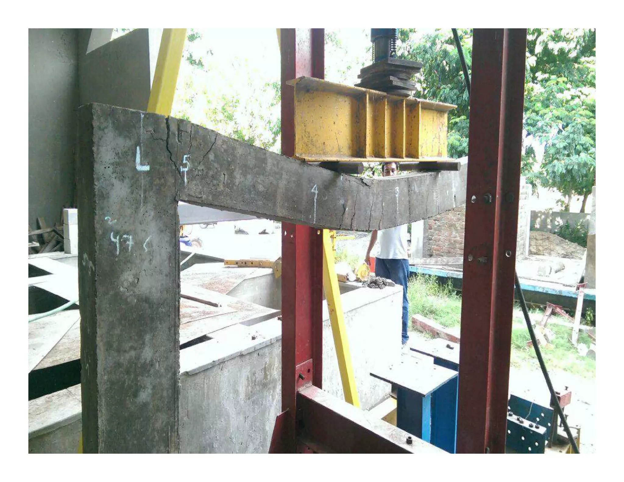
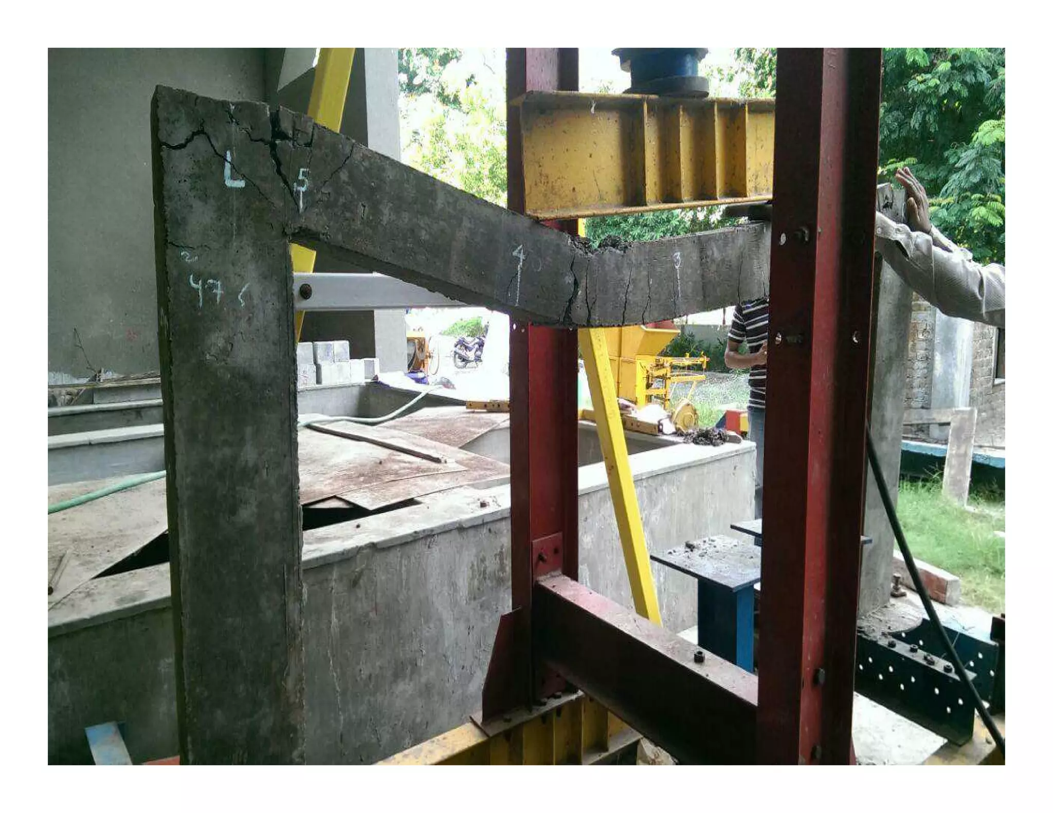

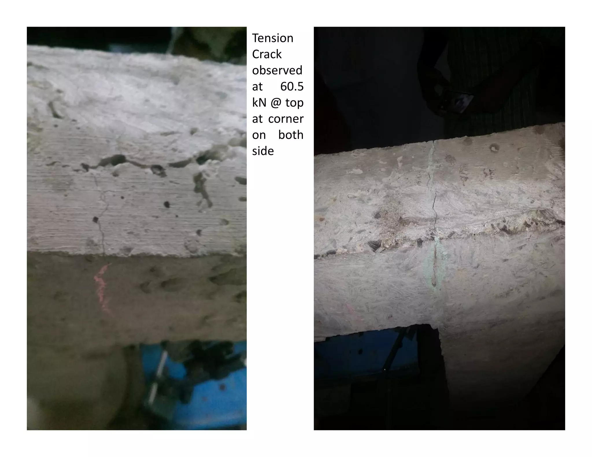
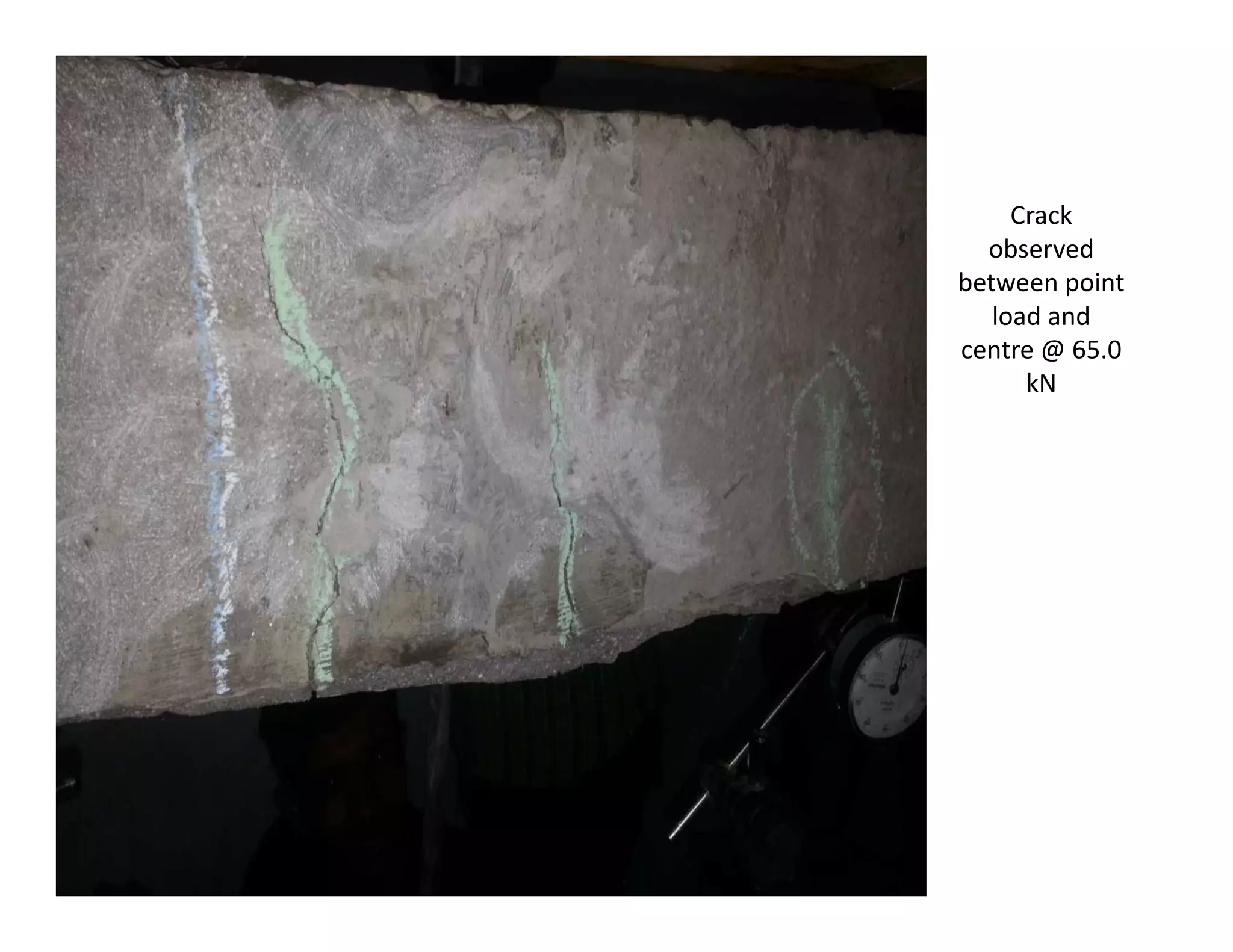
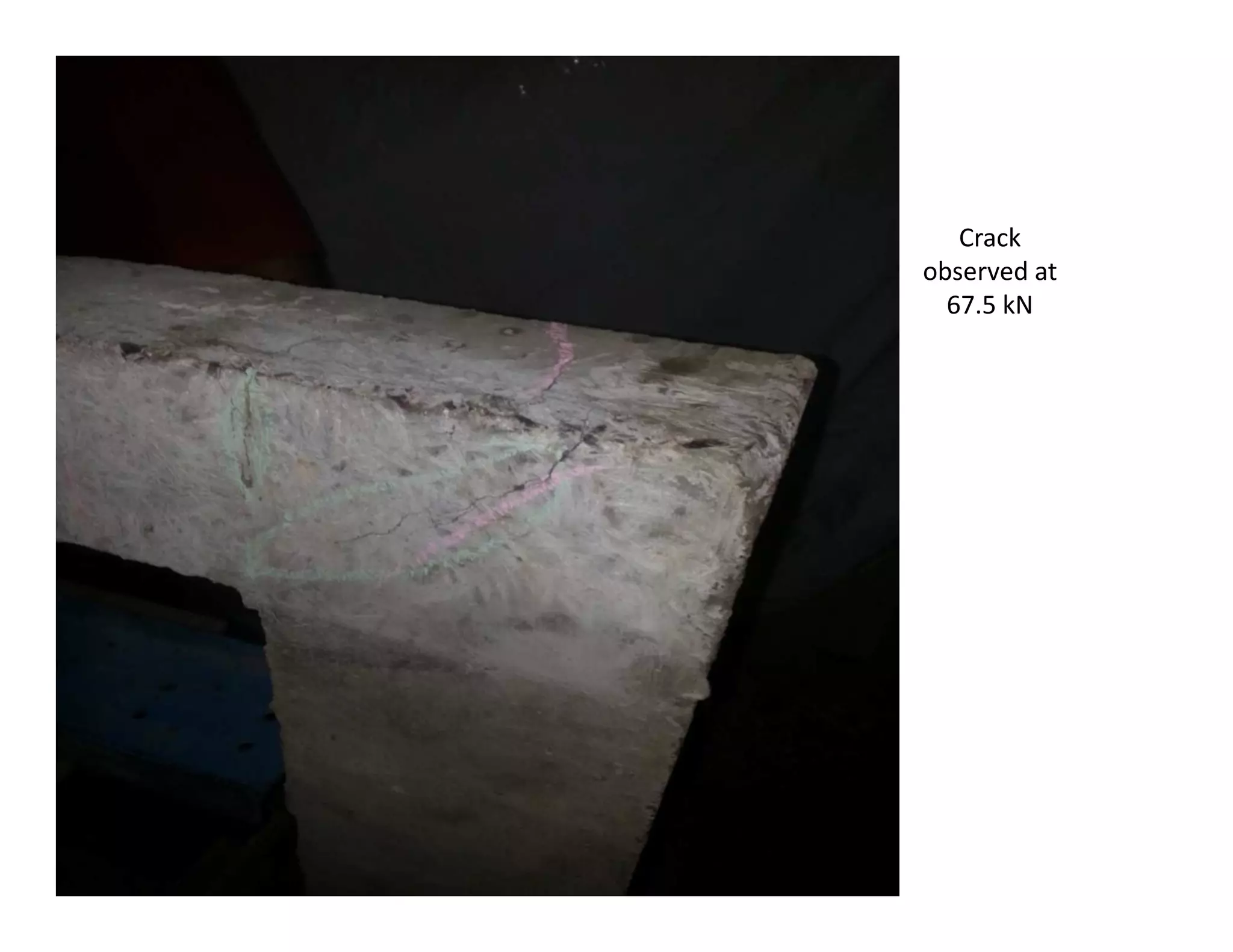
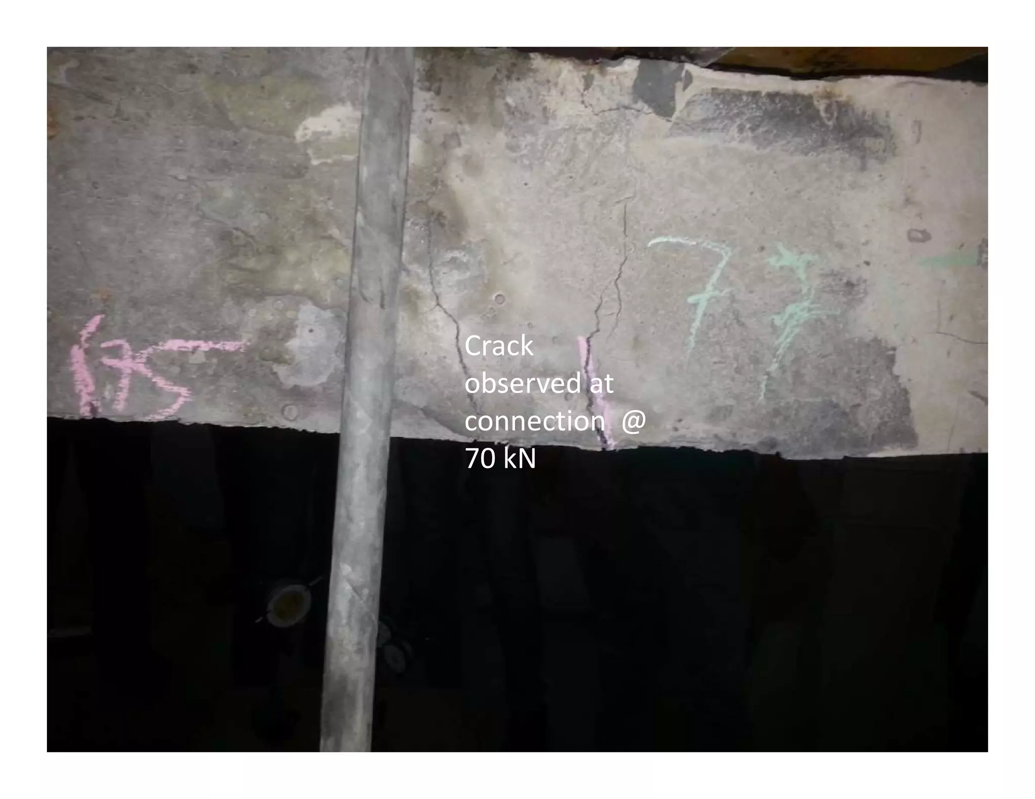
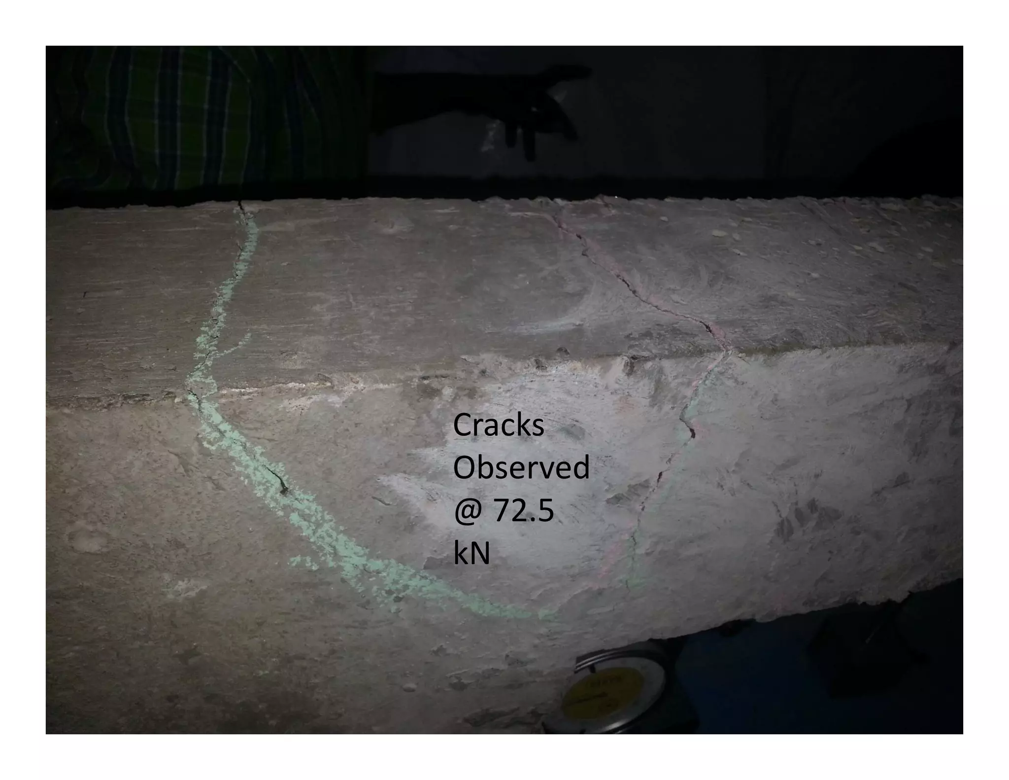
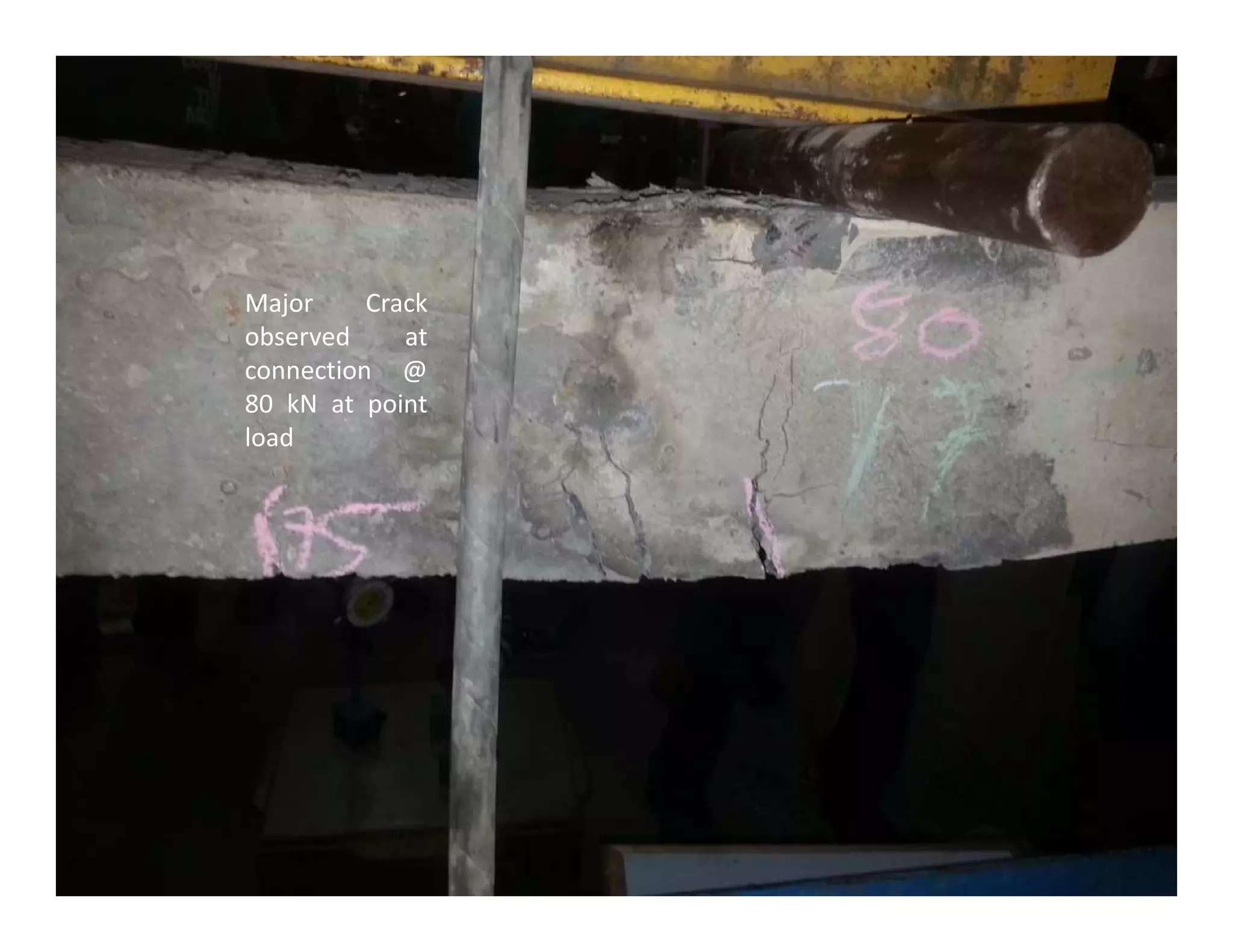
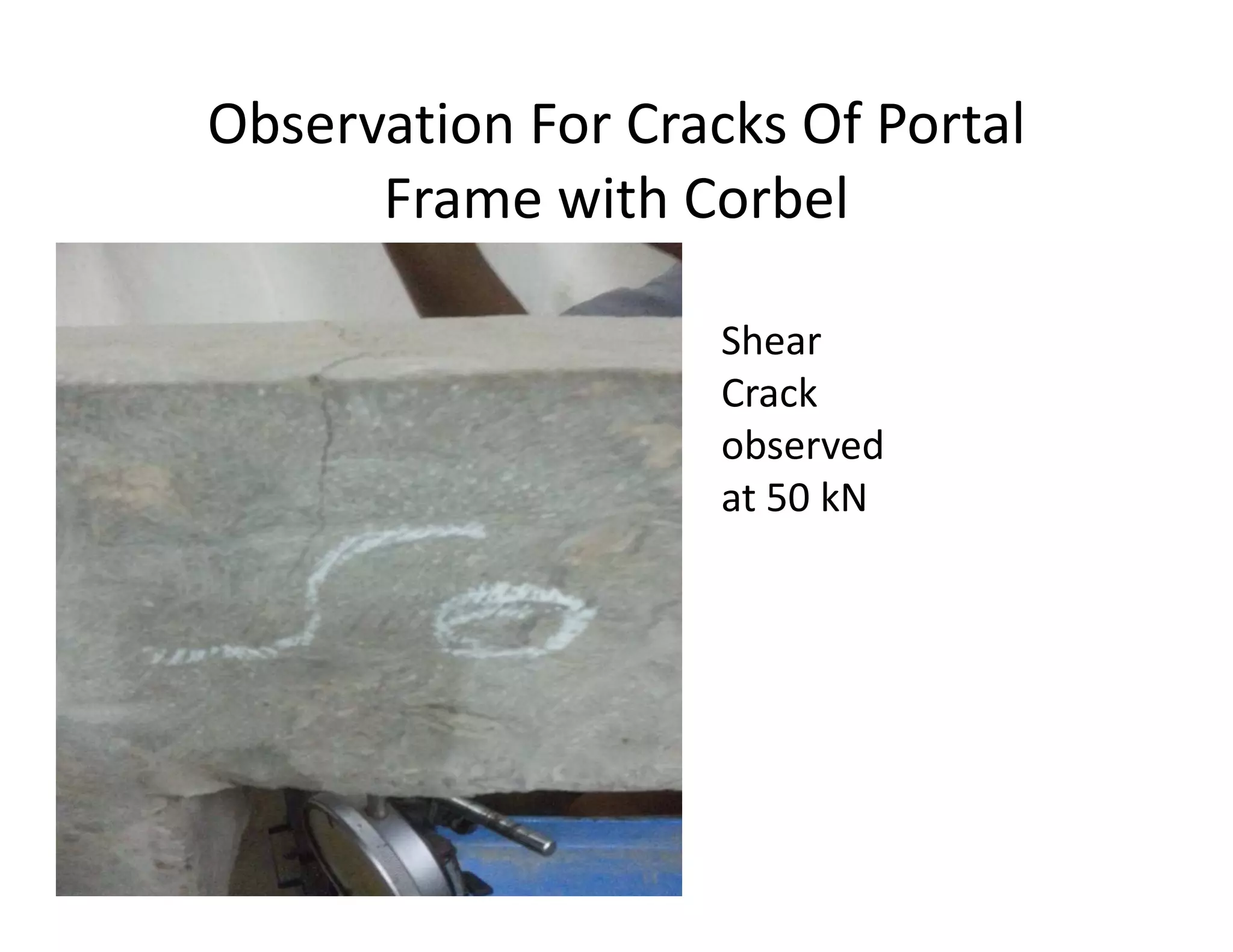
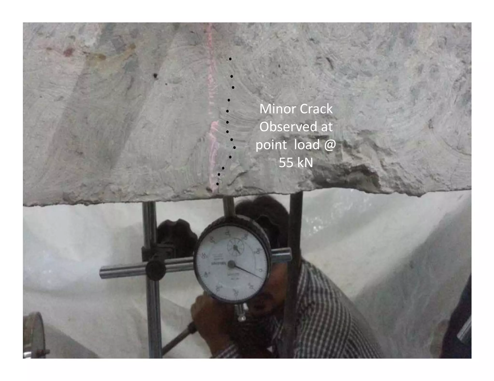
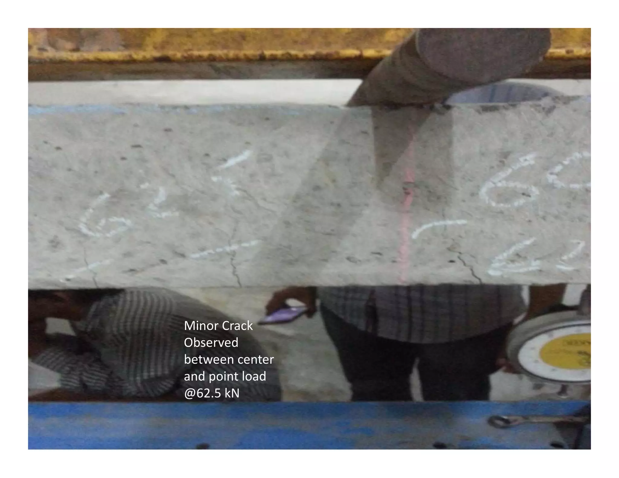
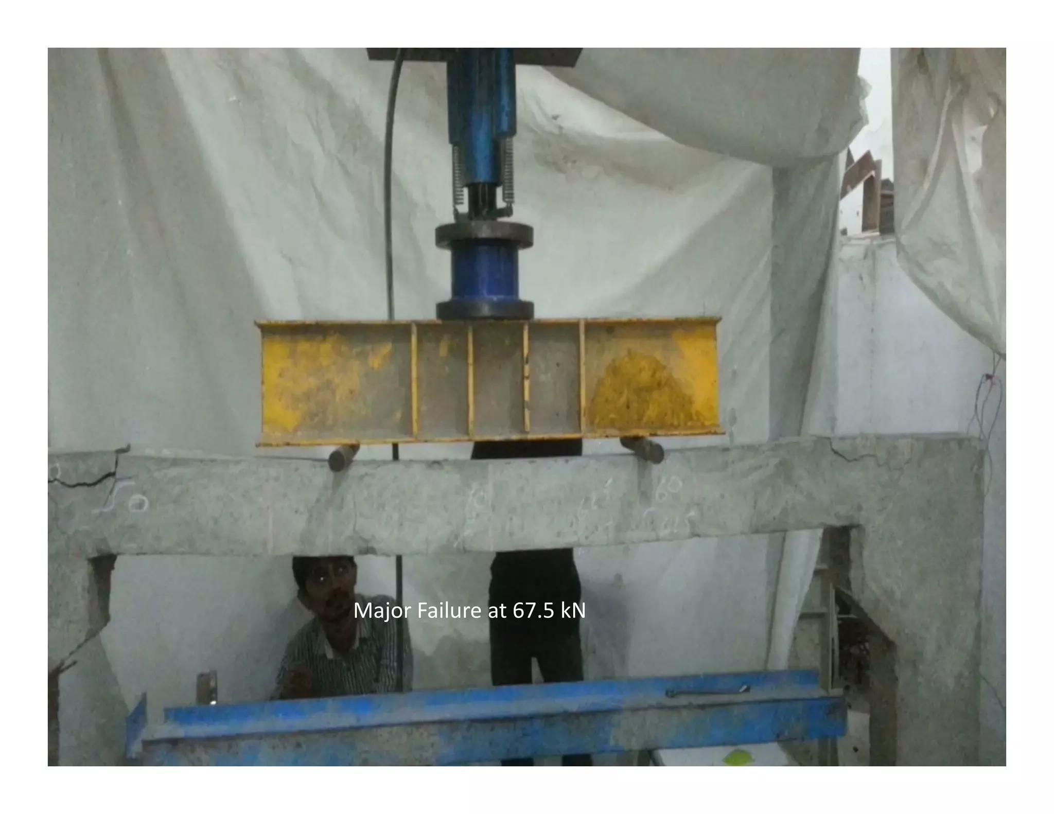
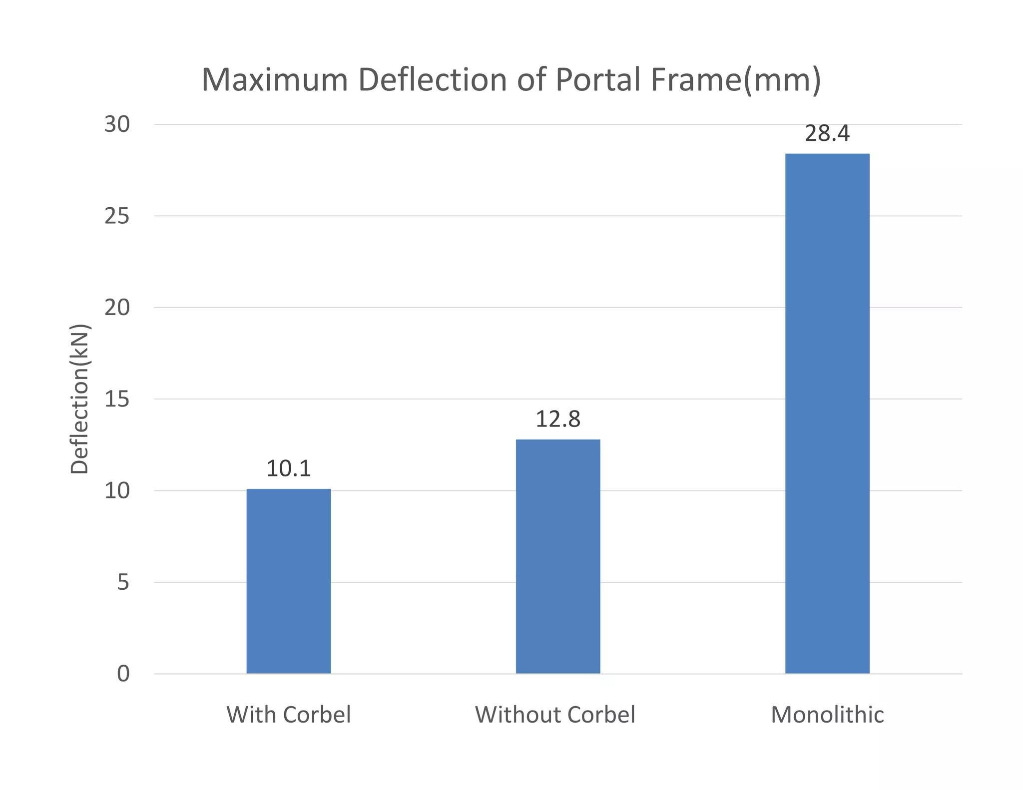
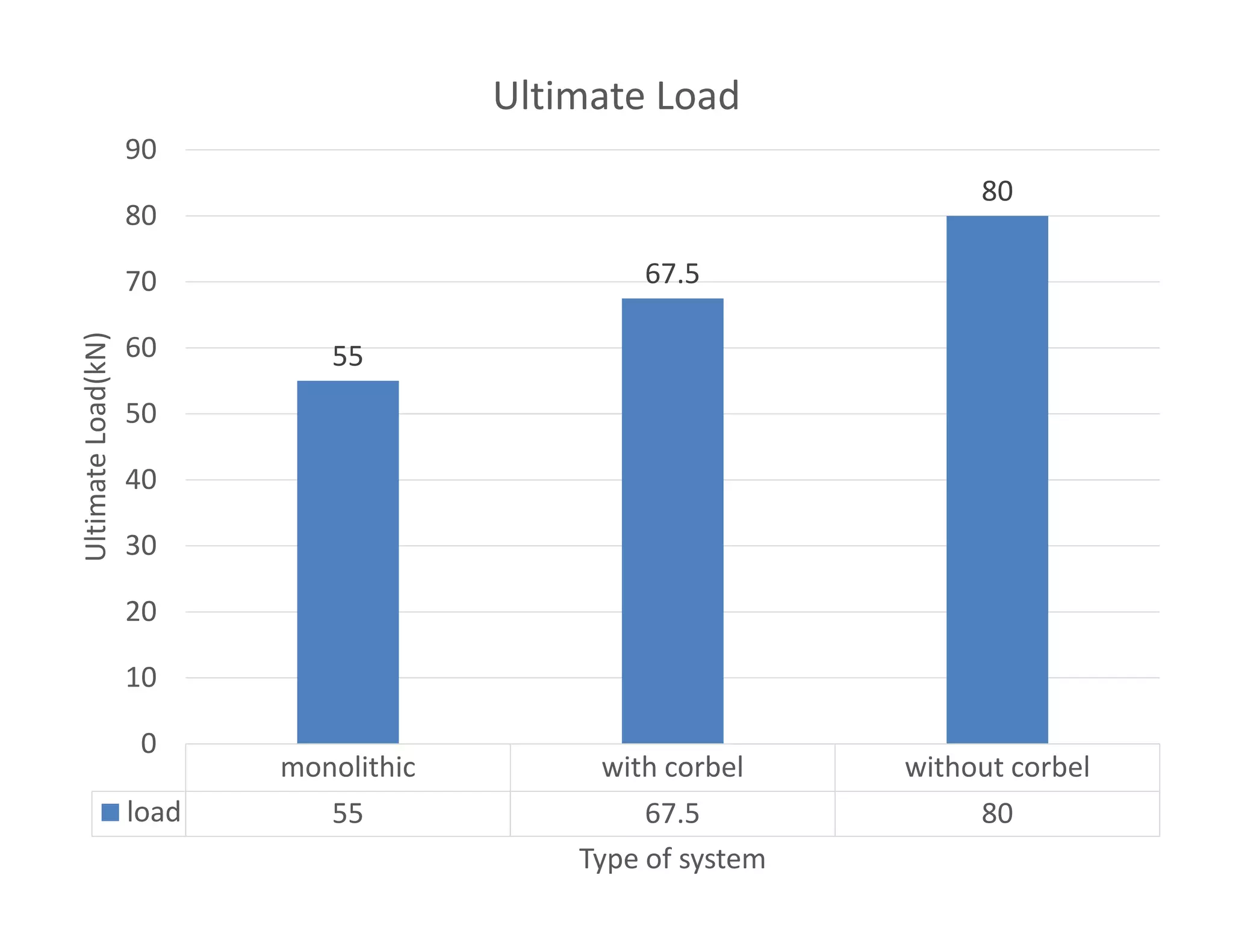
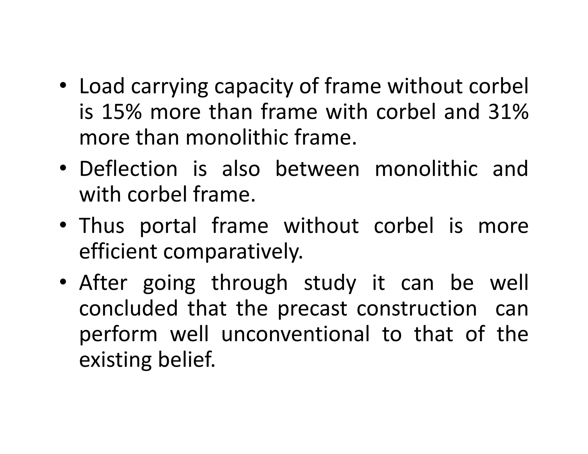

This document describes an experimental study comparing the structural behavior of monolithic and precast concrete portal frames. Scaled models of a monolithic frame and two precast frames (one with a corbel connection and one without) were tested under a two-point load. Test results showed that the monolithic frame had the highest deflections but lowest load capacity, while the precast frame with a corbel connection had the lowest deflections but highest load capacity. Cracks were first observed in the monolithic frame, followed by the precast frame without a corbel, with the frame with a corbel cracking at the highest loads. In conclusion, the monolithic frame was found to be the most ductile but least stiff, while


