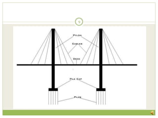
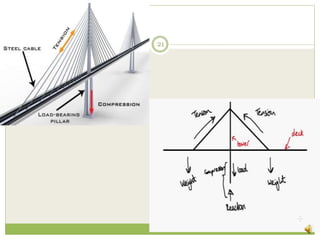
PA R A M AT H M E K A S
M . E . S T R U C T U RA L E N G I N E E R I N G
P. S . G C O L L E G E O F T E C H N O L O G Y
ANALYSIS OF CABLE
STAYED BRIDGES
1
Introduction
 Usually ,these approximately span for a length of
200 to 800 m
 Cable stayed bridges, modern type of bridge consists
of a continuous strong beams.
 A cable-stayed bridge has one or more towers, from
which cables support the bridge deck.
 The cables stretch diagonally between the pillars
and the beams.
 The cables are anchored in the tower rather than at
the end.
2
Cont…
3
 Requires less cables than a suspension bridge.
 Constructed using concrete, steel and composite
construction.
 Widely used type is pre-cast concrete structure.
 Can be constructed faster.
Around the world
Bandra, Mumbai Edong,China
4
Tatara,Japan Tarn Valley,France
5
Advantages of cable stayed bridge
 Used for larger span.
 Greater stiffness that suspension bridge , so
deformation of deck under live load is reduced
 Cantilever type of construction is followed.
 Cables act as both temporary and permanent
support
 Symmetrical bridge, the horizontal forces are
balance hence no large ground anchorage needed
6
Cantilever and symmetrical construction
7
Components of cable stayed bridge
 Super structure
1.pylon
2. cables
3. deck
 Sub structure
1. pile cap
2. pile foundation
8
9
Classification of cable stayed bridge
 Based on pylon
1.A- type
2.H- type
3. Y-type
 Based on arrangement of cable
1.radiating
2.harp
3. fan
4. star
10
Shapes of Pylon
11
Arrangement of cable
12
Pylon
13
 Pylons - support the weight and live load acting on
the structure
 They are chosen based on the structure, aesthetics,
length, and other environmental parameters.
 Pylons can be classified into two categories:
a) Steel Pylon
b) Concrete Pylon
Steel and concrete pylon
14
 Steel Pylons: steel boxes were used for construction
and bridges took the form of a steel portal frame.
Restraint is largely unnecessary as sufficient
transverse restraint can be provided within the stay
itself.
 Concrete Pylons: Concrete is very efficient when
supporting loads in axial compression.
high self-weight of the structure
Bridge deck
15
 The deck can be made of different materials such as
steel, concrete or composite steel concrete.
 choice of material- the overall cost of the
construction
 weight of the deck- required stay cables, pylons, and
foundations.
 Steel-concrete girders are attached by transverse
steel beams.
 The precast reinforced concrete deck is supported by
the main girders
Cont…
16
 This type of composite steel-concrete deck has more
advantages as follow:
weight of a composite deck is less than a concrete
deck.
 The light steel girders can be erected before applying
the heavy concrete slab.
 The stay cables have more resistance against
rotation anchoring to the outside steel main girders.
 The redistribution of compression forces due to
shrinkage and creep onto the steel girders is
minimized by using the precast slab.
Types of girdres
17
18
Construction Sequence
19
deck
cables
pylon
Pile cap
Pile
ground
Load
Transmission
20
21
Forces acting on the bridge
 Dead load
 Live load
 Wind load
 Seismic load
This leads to
 Bending moment
 Shear force
 Deflection
22
Dead load
 Own weight itself and all the parts and materials that
are used in the construction of bridge. The material
and parts that are self-modeled, their loads are
modeled separately to cover entire or actual self-
weight of the bridge.
 Wearing coat
 Handrail
 Kerb
 Pedestrians
23
Live load
 Indian Road Congress IRC: 6-2017 code is referred
for the moving load analysis of these cable stayed
bridge models. According to IRC specification for
two lanes, the live load combination of moving load
for two lanes both way traffic is Class 70R (W) on
one lane and Class A on both lanes.
24
Modeling
 Two different types of structural model
1. spine model
2. area object model
In spine model, the maximum positive shear force
differ from negative shear force, because spine
model is based on frame object
The maximum positive and negative shear force
in area object model is same because it is based
on area object.
25
Shear force
 Cable stayed bridge is analyzed with spine model and
area object model. This shear force is developed due
to combination of dead load and live load.
 The value of maximum positive shear force is nearly
10% less in case of area object model than to spine
model.
 Center of deck – spine model
 Ends of the deck – object model
26
Bending moment
 In spine model and area object model the maximum
positive bending moment is almost same.
 The value of maximum negative bending moment is
nearly 17% less in case of area object model as
compared to spine model.
 Maximum bending – centre of bridge.
27
Deflection
 The maximum deflection - centre of span,
combination of dead load and live load
 The increasing percentage of deflection in area object
model is more than 4%
28
Analysis
 Linear method of analysis of cable stayed bridges
 Non-linear method of analysis of cable stayed
bridges
 Strain energy method
 STAAD Pro software
29
Linear analysis
 Numerical type problem.
 Practically, cannot be used since the effect of
dynamic properties are not consider.
 Easy than other methods.
30
Non- linear analysis
 Considers all dynamic properties.
 Time history analysis and Modal analysis .
 To over come vibration due to earthquake, wind and
tides dampers are placed.
31
Strain energy method
 The method uses the potential energy of the stayed
girder with an iterative procedure.
 It was found that the iterative procedure is
convergent and that a small number of Fourier terms
is sufficient.
32
STAAD Pro analysis
 Most widely used in recent days
 Easy and accurate results
 Less time consuming
Steps in STAAD Pro
• a)Draw the geometry of the bridge by inserting
coordinates.
• b) Define the materials and sections for the members
• c) Define the loading values to be applied on the
structures.
• d) Now assign the defined section as the members.
• e) After assigning everything, set the analysis to be
carried out and press run analysis.
33
Cont..
34
 STAAD Pro will generate the various results like joint
displacements, joint behavior of the different shapes
of pylon forces, joint reactions, base reactions, deck
force, axial forces in cables and pylons, bending
moment in pylon, shear force in pylon, mode shapes
etc.
Tests on cable stayed bridge
 Wind tunnel test
 Fatigue test
 Tension load test on strands
 Inspection of anchorage
 Checking hardness of welds
 Rotative flexion test
35
Conclusion
 Cable stayed bridges are economical than suspension
bridges.
 Area object method is more accurate than spine
method.
 Cable stayed bridges are more stiffer.
 STAAD Pro widely used for analysis of cable stayed
bridges.
 Other methods are tedious and are becoming
obsolete.
36
References
37
 International Journal of Emerging Research in Management
& Technology ISSN: 2278-9359 - “Non-Linear Analysis of
Cable Stayed Bridges.”
 International journal of engineering research & technology –
“Analysis of Cable Stayed Bridge for Different Structural
Model”
 International Journal of Engineering and Techniques –
“Design and Analysis of Cable Stayed Bridge”
 Analysis of cable-stayed bridges during construction by
cantilever methods – Elsevier
 Overview of Cable Stayed Bridges – science direct.
THANK YOU
38

Analysis of cable stayed bridges

  • 1.
    PA R AM AT H M E K A S M . E . S T R U C T U RA L E N G I N E E R I N G P. S . G C O L L E G E O F T E C H N O L O G Y ANALYSIS OF CABLE STAYED BRIDGES 1
  • 2.
    Introduction  Usually ,theseapproximately span for a length of 200 to 800 m  Cable stayed bridges, modern type of bridge consists of a continuous strong beams.  A cable-stayed bridge has one or more towers, from which cables support the bridge deck.  The cables stretch diagonally between the pillars and the beams.  The cables are anchored in the tower rather than at the end. 2
  • 3.
    Cont… 3  Requires lesscables than a suspension bridge.  Constructed using concrete, steel and composite construction.  Widely used type is pre-cast concrete structure.  Can be constructed faster.
  • 4.
    Around the world Bandra,Mumbai Edong,China 4
  • 5.
  • 6.
    Advantages of cablestayed bridge  Used for larger span.  Greater stiffness that suspension bridge , so deformation of deck under live load is reduced  Cantilever type of construction is followed.  Cables act as both temporary and permanent support  Symmetrical bridge, the horizontal forces are balance hence no large ground anchorage needed 6
  • 7.
  • 8.
    Components of cablestayed bridge  Super structure 1.pylon 2. cables 3. deck  Sub structure 1. pile cap 2. pile foundation 8
  • 9.
  • 10.
    Classification of cablestayed bridge  Based on pylon 1.A- type 2.H- type 3. Y-type  Based on arrangement of cable 1.radiating 2.harp 3. fan 4. star 10
  • 11.
  • 12.
  • 13.
    Pylon 13  Pylons -support the weight and live load acting on the structure  They are chosen based on the structure, aesthetics, length, and other environmental parameters.  Pylons can be classified into two categories: a) Steel Pylon b) Concrete Pylon
  • 14.
    Steel and concretepylon 14  Steel Pylons: steel boxes were used for construction and bridges took the form of a steel portal frame. Restraint is largely unnecessary as sufficient transverse restraint can be provided within the stay itself.  Concrete Pylons: Concrete is very efficient when supporting loads in axial compression. high self-weight of the structure
  • 15.
    Bridge deck 15  Thedeck can be made of different materials such as steel, concrete or composite steel concrete.  choice of material- the overall cost of the construction  weight of the deck- required stay cables, pylons, and foundations.  Steel-concrete girders are attached by transverse steel beams.  The precast reinforced concrete deck is supported by the main girders
  • 16.
    Cont… 16  This typeof composite steel-concrete deck has more advantages as follow: weight of a composite deck is less than a concrete deck.  The light steel girders can be erected before applying the heavy concrete slab.  The stay cables have more resistance against rotation anchoring to the outside steel main girders.  The redistribution of compression forces due to shrinkage and creep onto the steel girders is minimized by using the precast slab.
  • 17.
  • 18.
  • 19.
  • 20.
  • 21.
  • 22.
    Forces acting onthe bridge  Dead load  Live load  Wind load  Seismic load This leads to  Bending moment  Shear force  Deflection 22
  • 23.
    Dead load  Ownweight itself and all the parts and materials that are used in the construction of bridge. The material and parts that are self-modeled, their loads are modeled separately to cover entire or actual self- weight of the bridge.  Wearing coat  Handrail  Kerb  Pedestrians 23
  • 24.
    Live load  IndianRoad Congress IRC: 6-2017 code is referred for the moving load analysis of these cable stayed bridge models. According to IRC specification for two lanes, the live load combination of moving load for two lanes both way traffic is Class 70R (W) on one lane and Class A on both lanes. 24
  • 25.
    Modeling  Two differenttypes of structural model 1. spine model 2. area object model In spine model, the maximum positive shear force differ from negative shear force, because spine model is based on frame object The maximum positive and negative shear force in area object model is same because it is based on area object. 25
  • 26.
    Shear force  Cablestayed bridge is analyzed with spine model and area object model. This shear force is developed due to combination of dead load and live load.  The value of maximum positive shear force is nearly 10% less in case of area object model than to spine model.  Center of deck – spine model  Ends of the deck – object model 26
  • 27.
    Bending moment  Inspine model and area object model the maximum positive bending moment is almost same.  The value of maximum negative bending moment is nearly 17% less in case of area object model as compared to spine model.  Maximum bending – centre of bridge. 27
  • 28.
    Deflection  The maximumdeflection - centre of span, combination of dead load and live load  The increasing percentage of deflection in area object model is more than 4% 28
  • 29.
    Analysis  Linear methodof analysis of cable stayed bridges  Non-linear method of analysis of cable stayed bridges  Strain energy method  STAAD Pro software 29
  • 30.
    Linear analysis  Numericaltype problem.  Practically, cannot be used since the effect of dynamic properties are not consider.  Easy than other methods. 30
  • 31.
    Non- linear analysis Considers all dynamic properties.  Time history analysis and Modal analysis .  To over come vibration due to earthquake, wind and tides dampers are placed. 31
  • 32.
    Strain energy method The method uses the potential energy of the stayed girder with an iterative procedure.  It was found that the iterative procedure is convergent and that a small number of Fourier terms is sufficient. 32
  • 33.
    STAAD Pro analysis Most widely used in recent days  Easy and accurate results  Less time consuming Steps in STAAD Pro • a)Draw the geometry of the bridge by inserting coordinates. • b) Define the materials and sections for the members • c) Define the loading values to be applied on the structures. • d) Now assign the defined section as the members. • e) After assigning everything, set the analysis to be carried out and press run analysis. 33
  • 34.
    Cont.. 34  STAAD Prowill generate the various results like joint displacements, joint behavior of the different shapes of pylon forces, joint reactions, base reactions, deck force, axial forces in cables and pylons, bending moment in pylon, shear force in pylon, mode shapes etc.
  • 35.
    Tests on cablestayed bridge  Wind tunnel test  Fatigue test  Tension load test on strands  Inspection of anchorage  Checking hardness of welds  Rotative flexion test 35
  • 36.
    Conclusion  Cable stayedbridges are economical than suspension bridges.  Area object method is more accurate than spine method.  Cable stayed bridges are more stiffer.  STAAD Pro widely used for analysis of cable stayed bridges.  Other methods are tedious and are becoming obsolete. 36
  • 37.
    References 37  International Journalof Emerging Research in Management & Technology ISSN: 2278-9359 - “Non-Linear Analysis of Cable Stayed Bridges.”  International journal of engineering research & technology – “Analysis of Cable Stayed Bridge for Different Structural Model”  International Journal of Engineering and Techniques – “Design and Analysis of Cable Stayed Bridge”  Analysis of cable-stayed bridges during construction by cantilever methods – Elsevier  Overview of Cable Stayed Bridges – science direct.
  • 38.