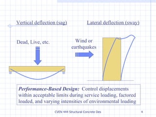
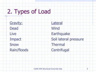
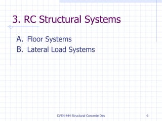
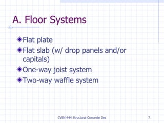
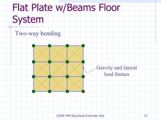
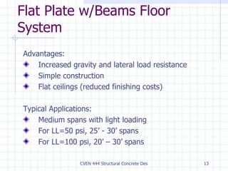
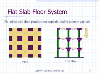
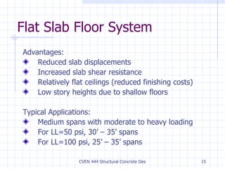
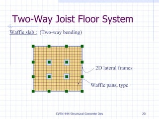
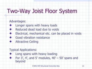
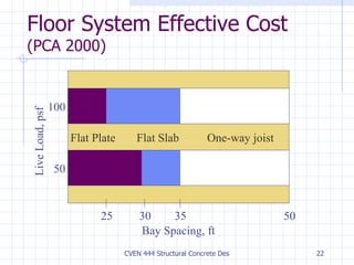
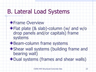
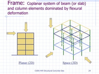
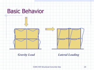
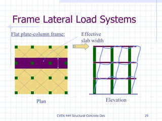
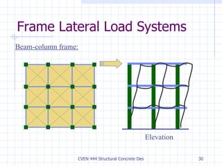
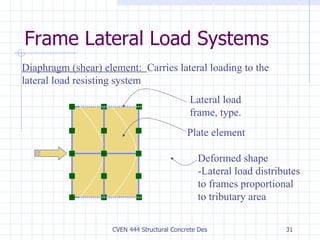
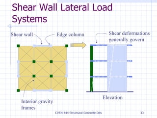
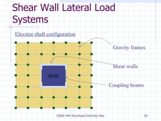
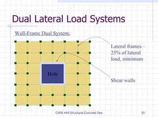
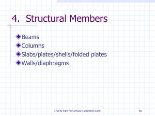
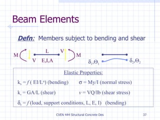
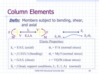
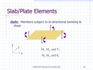
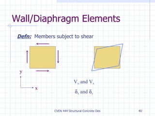
CVEN 444 Structural Concrete Design Structural System Overview Dr. E. Sandt Summer 2003 Semester
Presentation Overview Building system primary functions Types of load RC structural systems RC structural members
1. Basic Building System Functions Support gravity loads for strength and serviceability during: Normal use (service) conditions Maximum considered use conditions Environmental loading of varying intensities
Lateral deflection (sway) Wind or earthquakes Vertical deflection (sag) Dead, Live, etc. Performance-Based Design:   Control displacements within acceptable limits during service loading, factored loaded, and varying intensities of environmental loading
2. Types of Load Gravity: Dead Live Impact Snow Rain/floods Lateral Wind Earthquake Soil lateral pressure Thermal Centrifugal
3. RC Structural Systems Floor Systems Lateral Load Systems
A. Floor Systems Flat plate Flat slab (w/ drop panels and/or capitals) One-way joist system Two-way waffle system
Flat Plate Floor System  Slab-column frame system in two-way bending Plan Elevation
Flat Plate Floor System Advantages: Simple construction Flat ceilings (reduced finishing costs) Low story heights due to shallow floors Typical Applications: Short-to-medium spans with light loading For LL=50 psi, 15’ - 30’ spans For LL=100 psi, 15’ – 25’ spans
Flat Plate w/Spandrel Beam System Plan Elevation
Flat Plate w/Spandrel Beam System Advantages: Same as flat plate system, plus  Increased gravity and lateral load resistance Increased torsional resistance Decreased slab edge displacements Typical Applications: Same as flat plate systems
Flat Plate w/Beams Floor System Gravity and lateral load frames Two-way bending
Flat Plate w/Beams Floor System Advantages: Increased gravity and lateral load resistance Simple construction Flat ceilings (reduced finishing costs) Typical Applications: Medium spans with light loading For LL=50 psi, 25’ - 30’ spans For LL=100 psi, 20’ – 30’ spans
Flat Slab Floor System Flat plate with drop panels,shear capitals, and/or column capitals Plan Elevation
Flat Slab Floor System Advantages: Reduced slab displacements Increased slab shear resistance Relatively flat ceilings (reduced finishing costs) Low story heights due to shallow floors Typical Applications: Medium spans with moderate to heavy loading For LL=50 psi, 30’ – 35’ spans For LL=100 psi, 25’ – 35’ spans
One-Way Joist Floor System 2D lateral frames Floor joists, type Rib (joist) slab :   (One-way bending) 2D gravity or lateral frames
One-Way Joist Floor System Lateral space frame Floor joists, type Rib (joist) slab with beams:   (One-way bending)
One-Way Joist Floor System 2’ or 3’ cc. – Joists 4’ or 6’ cc. – Skip joists 5’ or 6’ cc – Wide-module joists Top of Slab 1:12 Slope, type 8-24” for 30” Modules 16-24” for 53” Modules 14-24” for 66” Modules . Width varies 4”, 6” or larger Typical Joist
One-Way Joist Floor System Advantages: Longer spans with heavy loads Reduced dead load due to voids Electrical, mechanical etc. can be placed between voids Good vibration resistance Typical Applications: Medium-to-long spans with heavy loading For 30” modules, 35’ – 40’ spans For 53” & 66” modules, 35’ – 50’ spans
Two-Way Joist Floor System 2D lateral frames Waffle pans, type Waffle slab :   (Two-way bending)
Two-Way Joist Floor System Advantages: Longer spans with heavy loads Reduced dead load due to voids Electrical, mechanical etc. can be placed in voids Good vibration resistance Attractive Ceiling Typical Applications: Long spans with heavy loading For 3’, 4’, and 5’ modules, 40’ – 50’ spans and beyond
Floor System Effective Cost (PCA 2000) Bay Spacing, ft Live Load, psf 100 50 25 30 35 50 One-way joist Flat Slab Flat Plate
B. Lateral Load Systems Frame Overview Flat plate (& slab)-column (w/ and w/o drop panels and/or capitals) frame systems Beam-column frame systems Shear wall systems (building frame and bearing wall) Dual systems (frames and shear walls)
Frame:   Coplanar system of beam (or slab) and column elements dominated by flexural deformation Planar (2D) Space (3D)
Basic Behavior Gravity Load Lateral Loading
2D vs. 3D Frames (Plan) Planar Space Floor joists, type 2 or 4 frames  , 2 frames 4 frames  , 4 frames
Frame Advantages Optimum use of floor space, ie. optimal for office buildings, retail, parking structures where open space is required. Relatively simple and experienced construction process Generally economical for low-to mid-rise construction (less than about 20 stories) In Houston, most frames are made of reinforced concrete.
Frame Disadvantages Generally, frames are flexible structures and lateral deflections generally control the design process for buildings with greater than about 4 stories.  Note that concrete frames are about 8 times stiffer than steel frames of the same strength. Span lengths are limited when using normal reinforced concrete (generally less than about 40 ft, but up to about 50 ft).  Span lengths can be increased by using pre-stressed concrete.
Frame Lateral Load Systems Flat plate-column frame: Plan Elevation Effective slab width
Frame Lateral Load Systems Beam-column frame: Elevation
Frame Lateral Load Systems Diaphragm (shear) element:  Carries lateral loading to the lateral load resisting system Lateral load frame, type. Plate element Deformed shape -Lateral load distributes to frames proportional to tributary area
Frame Lateral Load Systems For relatively square plans, diaphragms are generally considered rigid Space frame with square plan Deformed shape has constant lateral displacement -  No diaphragm flexibility, ie. lateral load distributes to frame proportional to frame stiffness
Shear Wall Lateral Load Systems Shear wall Elevation Edge column Interior gravity frames Shear deformations generally govern
Shear Wall Lateral Load Systems Gravity frames Shear walls Coupling beams Elevator shaft configuration Hole
Dual Lateral Load Systems Lateral frames – 25% of lateral load, minimum Shear walls Wall-Frame Dual System: Hole
4.  Structural Members Beams Columns Slabs/plates/shells/folded plates Walls/diaphragms
Beam Elements Defn :   Members subject to bending and shear Elastic Properties: k b  =  f  ( EI/L n ) (bending)   = My/I (normal stress) k s  = GA/L (shear) v  = VQ/Ib (shear stress)   b  =  f  (load, support conditions, L, E, I)  (bending)         V V L E,I,A M M
Column Elements Defn:   Members subject to bending, shear,      and axial Elastic Properties: k a  = EA/L (axial)   a  = F/A (normal stress) k b  =  f  ( EI/L n ) (bending)  b  = My/I (normal stress) k s  = GA/L (shear) v  = VQ/Ib (shear stress)   b  =  f  (load, support conditions, L, E, I, A)  (normal) V V L E,I,A M M F F          
Slab/Plate Elements Defn :   Members subject to bi-directional bending & shear x y z M x , M y , and V z  x ,   y , and   z
Wall/Diaphragm Elements Defn:   Members subject to shear x y V x  and V x  x  and   y

Structural System Overview

  • 1.
    CVEN 444 StructuralConcrete Design Structural System Overview Dr. E. Sandt Summer 2003 Semester
  • 2.
    Presentation Overview Buildingsystem primary functions Types of load RC structural systems RC structural members
  • 3.
    1. Basic BuildingSystem Functions Support gravity loads for strength and serviceability during: Normal use (service) conditions Maximum considered use conditions Environmental loading of varying intensities
  • 4.
    Lateral deflection (sway)Wind or earthquakes Vertical deflection (sag) Dead, Live, etc. Performance-Based Design: Control displacements within acceptable limits during service loading, factored loaded, and varying intensities of environmental loading
  • 5.
    2. Types ofLoad Gravity: Dead Live Impact Snow Rain/floods Lateral Wind Earthquake Soil lateral pressure Thermal Centrifugal
  • 6.
    3. RC StructuralSystems Floor Systems Lateral Load Systems
  • 7.
    A. Floor SystemsFlat plate Flat slab (w/ drop panels and/or capitals) One-way joist system Two-way waffle system
  • 8.
    Flat Plate FloorSystem Slab-column frame system in two-way bending Plan Elevation
  • 9.
    Flat Plate FloorSystem Advantages: Simple construction Flat ceilings (reduced finishing costs) Low story heights due to shallow floors Typical Applications: Short-to-medium spans with light loading For LL=50 psi, 15’ - 30’ spans For LL=100 psi, 15’ – 25’ spans
  • 10.
    Flat Plate w/SpandrelBeam System Plan Elevation
  • 11.
    Flat Plate w/SpandrelBeam System Advantages: Same as flat plate system, plus Increased gravity and lateral load resistance Increased torsional resistance Decreased slab edge displacements Typical Applications: Same as flat plate systems
  • 12.
    Flat Plate w/BeamsFloor System Gravity and lateral load frames Two-way bending
  • 13.
    Flat Plate w/BeamsFloor System Advantages: Increased gravity and lateral load resistance Simple construction Flat ceilings (reduced finishing costs) Typical Applications: Medium spans with light loading For LL=50 psi, 25’ - 30’ spans For LL=100 psi, 20’ – 30’ spans
  • 14.
    Flat Slab FloorSystem Flat plate with drop panels,shear capitals, and/or column capitals Plan Elevation
  • 15.
    Flat Slab FloorSystem Advantages: Reduced slab displacements Increased slab shear resistance Relatively flat ceilings (reduced finishing costs) Low story heights due to shallow floors Typical Applications: Medium spans with moderate to heavy loading For LL=50 psi, 30’ – 35’ spans For LL=100 psi, 25’ – 35’ spans
  • 16.
    One-Way Joist FloorSystem 2D lateral frames Floor joists, type Rib (joist) slab : (One-way bending) 2D gravity or lateral frames
  • 17.
    One-Way Joist FloorSystem Lateral space frame Floor joists, type Rib (joist) slab with beams: (One-way bending)
  • 18.
    One-Way Joist FloorSystem 2’ or 3’ cc. – Joists 4’ or 6’ cc. – Skip joists 5’ or 6’ cc – Wide-module joists Top of Slab 1:12 Slope, type 8-24” for 30” Modules 16-24” for 53” Modules 14-24” for 66” Modules . Width varies 4”, 6” or larger Typical Joist
  • 19.
    One-Way Joist FloorSystem Advantages: Longer spans with heavy loads Reduced dead load due to voids Electrical, mechanical etc. can be placed between voids Good vibration resistance Typical Applications: Medium-to-long spans with heavy loading For 30” modules, 35’ – 40’ spans For 53” & 66” modules, 35’ – 50’ spans
  • 20.
    Two-Way Joist FloorSystem 2D lateral frames Waffle pans, type Waffle slab : (Two-way bending)
  • 21.
    Two-Way Joist FloorSystem Advantages: Longer spans with heavy loads Reduced dead load due to voids Electrical, mechanical etc. can be placed in voids Good vibration resistance Attractive Ceiling Typical Applications: Long spans with heavy loading For 3’, 4’, and 5’ modules, 40’ – 50’ spans and beyond
  • 22.
    Floor System EffectiveCost (PCA 2000) Bay Spacing, ft Live Load, psf 100 50 25 30 35 50 One-way joist Flat Slab Flat Plate
  • 23.
    B. Lateral LoadSystems Frame Overview Flat plate (& slab)-column (w/ and w/o drop panels and/or capitals) frame systems Beam-column frame systems Shear wall systems (building frame and bearing wall) Dual systems (frames and shear walls)
  • 24.
    Frame: Coplanar system of beam (or slab) and column elements dominated by flexural deformation Planar (2D) Space (3D)
  • 25.
    Basic Behavior GravityLoad Lateral Loading
  • 26.
    2D vs. 3DFrames (Plan) Planar Space Floor joists, type 2 or 4 frames , 2 frames 4 frames , 4 frames
  • 27.
    Frame Advantages Optimumuse of floor space, ie. optimal for office buildings, retail, parking structures where open space is required. Relatively simple and experienced construction process Generally economical for low-to mid-rise construction (less than about 20 stories) In Houston, most frames are made of reinforced concrete.
  • 28.
    Frame Disadvantages Generally,frames are flexible structures and lateral deflections generally control the design process for buildings with greater than about 4 stories. Note that concrete frames are about 8 times stiffer than steel frames of the same strength. Span lengths are limited when using normal reinforced concrete (generally less than about 40 ft, but up to about 50 ft). Span lengths can be increased by using pre-stressed concrete.
  • 29.
    Frame Lateral LoadSystems Flat plate-column frame: Plan Elevation Effective slab width
  • 30.
    Frame Lateral LoadSystems Beam-column frame: Elevation
  • 31.
    Frame Lateral LoadSystems Diaphragm (shear) element: Carries lateral loading to the lateral load resisting system Lateral load frame, type. Plate element Deformed shape -Lateral load distributes to frames proportional to tributary area
  • 32.
    Frame Lateral LoadSystems For relatively square plans, diaphragms are generally considered rigid Space frame with square plan Deformed shape has constant lateral displacement - No diaphragm flexibility, ie. lateral load distributes to frame proportional to frame stiffness
  • 33.
    Shear Wall LateralLoad Systems Shear wall Elevation Edge column Interior gravity frames Shear deformations generally govern
  • 34.
    Shear Wall LateralLoad Systems Gravity frames Shear walls Coupling beams Elevator shaft configuration Hole
  • 35.
    Dual Lateral LoadSystems Lateral frames – 25% of lateral load, minimum Shear walls Wall-Frame Dual System: Hole
  • 36.
    4. StructuralMembers Beams Columns Slabs/plates/shells/folded plates Walls/diaphragms
  • 37.
    Beam Elements Defn: Members subject to bending and shear Elastic Properties: k b = f ( EI/L n ) (bending)  = My/I (normal stress) k s = GA/L (shear) v = VQ/Ib (shear stress)   b = f (load, support conditions, L, E, I) (bending)         V V L E,I,A M M
  • 38.
    Column Elements Defn: Members subject to bending, shear, and axial Elastic Properties: k a = EA/L (axial)  a = F/A (normal stress) k b = f ( EI/L n ) (bending)  b = My/I (normal stress) k s = GA/L (shear) v = VQ/Ib (shear stress)   b = f (load, support conditions, L, E, I, A) (normal) V V L E,I,A M M F F          
  • 39.
    Slab/Plate Elements Defn: Members subject to bi-directional bending & shear x y z M x , M y , and V z  x ,  y , and  z
  • 40.
    Wall/Diaphragm Elements Defn: Members subject to shear x y V x and V x  x and  y