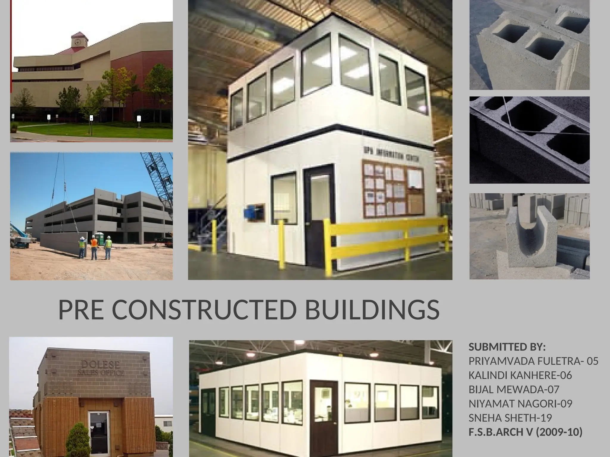
PRE CONSTRUCTED BUILDINGS
SUBMITTEDBY:
PRIYAMVADA FULETRA- 05
KALINDI KANHERE-06
BIJAL MEWADA-07
NIYAMAT NAGORI-09
SNEHA SHETH-19
F.S.B.ARCH V (2009-10)
2.
PRECAST CONCRETE CONSTRUCTION
PRECASTCONCRETE CONSTRUCTION
INTRODUCTION:
INTRODUCTION:
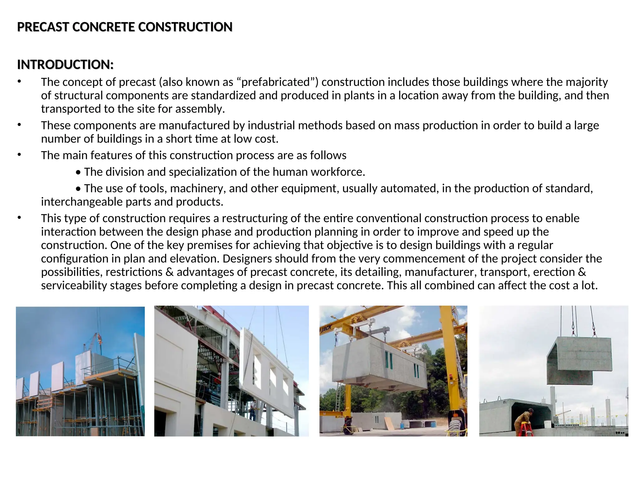
• The concept of precast (also known as “prefabricated”) construction includes those buildings where the majority
of structural components are standardized and produced in plants in a location away from the building, and then
transported to the site for assembly.
• These components are manufactured by industrial methods based on mass production in order to build a large
number of buildings in a short time at low cost.
• The main features of this construction process are as follows
• The division and specialization of the human workforce.
• The use of tools, machinery, and other equipment, usually automated, in the production of standard,
interchangeable parts and products.
• This type of construction requires a restructuring of the entire conventional construction process to enable
interaction between the design phase and production planning in order to improve and speed up the
construction. One of the key premises for achieving that objective is to design buildings with a regular
configuration in plan and elevation. Designers should from the very commencement of the project consider the
possibilities, restrictions & advantages of precast concrete, its detailing, manufacturer, transport, erection &
serviceability stages before completing a design in precast concrete. This all combined can affect the cost a lot.
3.
• Every constructionmaterial & system has its own characteristics which influence the layout, span length,
construction depth, stability system, etc. Same holds true for precast concrete , not only in comparison to steel,
wood, & masonry structures, but also with respect to cast in-situ concrete.
• Theoretically, all joints between the precast units could be made in such a way that the completed precast
structure has the same monolithic concept as a in-situ one. However, this approach is very labour intensive &
costly. If the full advantages of precast concrete are to be realized, the structure should be conceived according to
its specific design requisites.
CATEGORIES OF PRECAST BUILDING SYSTEMS
CATEGORIES OF PRECAST BUILDING SYSTEMS
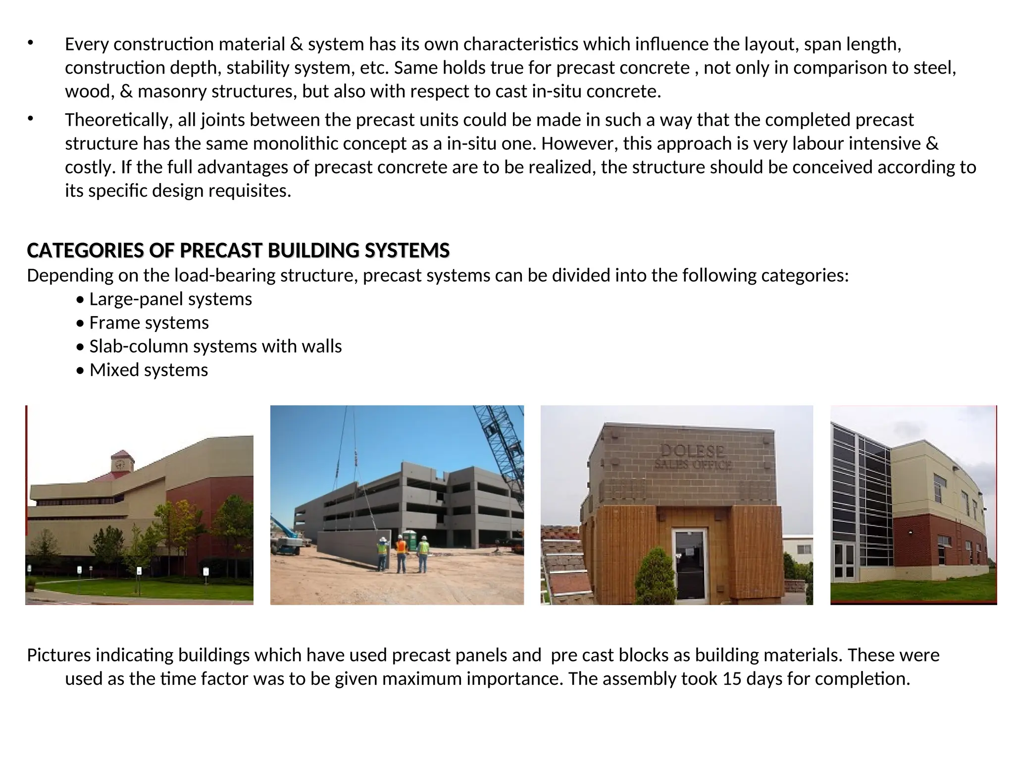
Depending on the load-bearing structure, precast systems can be divided into the following categories:
• Large-panel systems
• Frame systems
• Slab-column systems with walls
• Mixed systems
Pictures indicating buildings which have used precast panels and pre cast blocks as building materials. These were
used as the time factor was to be given maximum importance. The assembly took 15 days for completion.
4.
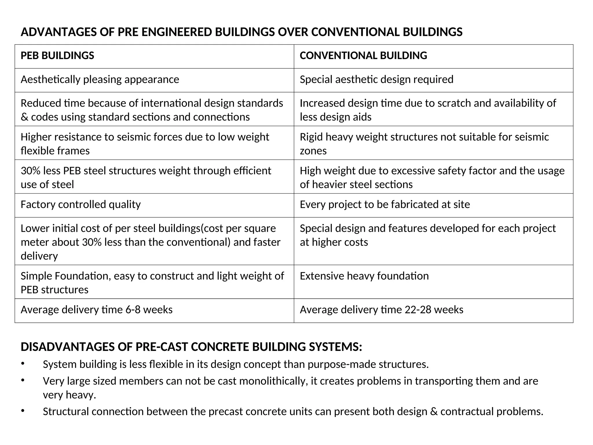
ADVANTAGES OF PREENGINEERED BUILDINGS OVER CONVENTIONAL BUILDINGS
PEB BUILDINGS CONVENTIONAL BUILDING
Aesthetically pleasing appearance Special aesthetic design required
Reduced time because of international design standards
& codes using standard sections and connections
Increased design time due to scratch and availability of
less design aids
Higher resistance to seismic forces due to low weight
flexible frames
Rigid heavy weight structures not suitable for seismic
zones
30% less PEB steel structures weight through efficient
use of steel
High weight due to excessive safety factor and the usage
of heavier steel sections
Factory controlled quality Every project to be fabricated at site
Lower initial cost of per steel buildings(cost per square
meter about 30% less than the conventional) and faster
delivery
Special design and features developed for each project
at higher costs
Simple Foundation, easy to construct and light weight of
PEB structures
Extensive heavy foundation
Average delivery time 6-8 weeks Average delivery time 22-28 weeks
DISADVANTAGES OF PRE-CAST CONCRETE BUILDING SYSTEMS:
• System building is less flexible in its design concept than purpose-made structures.
• Very large sized members can not be cast monolithically, it creates problems in transporting them and are
very heavy.
• Structural connection between the precast concrete units can present both design & contractual problems.
5.
1.
1. LARGE-PANEL SYSTEMS
LARGE-PANELSYSTEMS
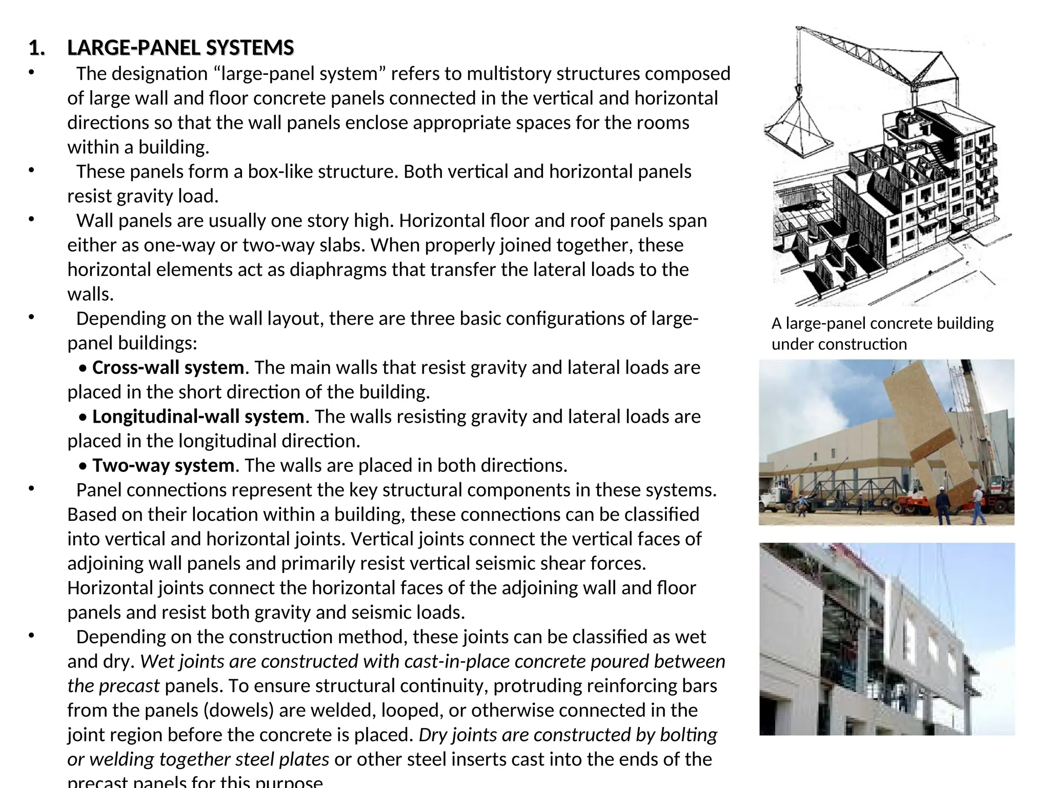
• The designation “large-panel system” refers to multistory structures composed
of large wall and floor concrete panels connected in the vertical and horizontal
directions so that the wall panels enclose appropriate spaces for the rooms
within a building.
• These panels form a box-like structure. Both vertical and horizontal panels
resist gravity load.
• Wall panels are usually one story high. Horizontal floor and roof panels span
either as one-way or two-way slabs. When properly joined together, these
horizontal elements act as diaphragms that transfer the lateral loads to the
walls.
• Depending on the wall layout, there are three basic configurations of large-
panel buildings:
• Cross-wall system. The main walls that resist gravity and lateral loads are
placed in the short direction of the building.
• Longitudinal-wall system. The walls resisting gravity and lateral loads are
placed in the longitudinal direction.
• Two-way system. The walls are placed in both directions.
• Panel connections represent the key structural components in these systems.
Based on their location within a building, these connections can be classified
into vertical and horizontal joints. Vertical joints connect the vertical faces of
adjoining wall panels and primarily resist vertical seismic shear forces.
Horizontal joints connect the horizontal faces of the adjoining wall and floor
panels and resist both gravity and seismic loads.
• Depending on the construction method, these joints can be classified as wet
and dry. Wet joints are constructed with cast-in-place concrete poured between
the precast panels. To ensure structural continuity, protruding reinforcing bars
from the panels (dowels) are welded, looped, or otherwise connected in the
joint region before the concrete is placed. Dry joints are constructed by bolting
or welding together steel plates or other steel inserts cast into the ends of the
A large-panel concrete building
under construction
6.
2.
2. FRAME SYSTEMS:
FRAMESYSTEMS:
• Precast concrete frames involve an entire structure being fabricated off-
site. In addition, structural components can be supplied for incorporation
into a structure on-site. Frames can simultaneously achieve both
structural and decorative design requirements - a wide variety of mixes,
colours and finishes can be accommodated.
• Precast frames can be constructed using either linear elements or spatial
beam-column sub assemblages. Precast beam-column sub assemblages
have the advantage that the connecting faces between the sub
assemblages can be placed away from the critical frame regions;
however, linear elements are generally preferred because of the
difficulties associated with forming, handling, and erecting spatial
elements.
• The beams can be seated on corbels at the columns, for ease of
construction and to aid the shear transfer from the beam to the column.
The beam-column joints accomplished in this way are hinged. However,
rigid beam-column connections are used in some cases, when the
continuity of longitudinal reinforcement through the beam-column joint
needs to be ensured.
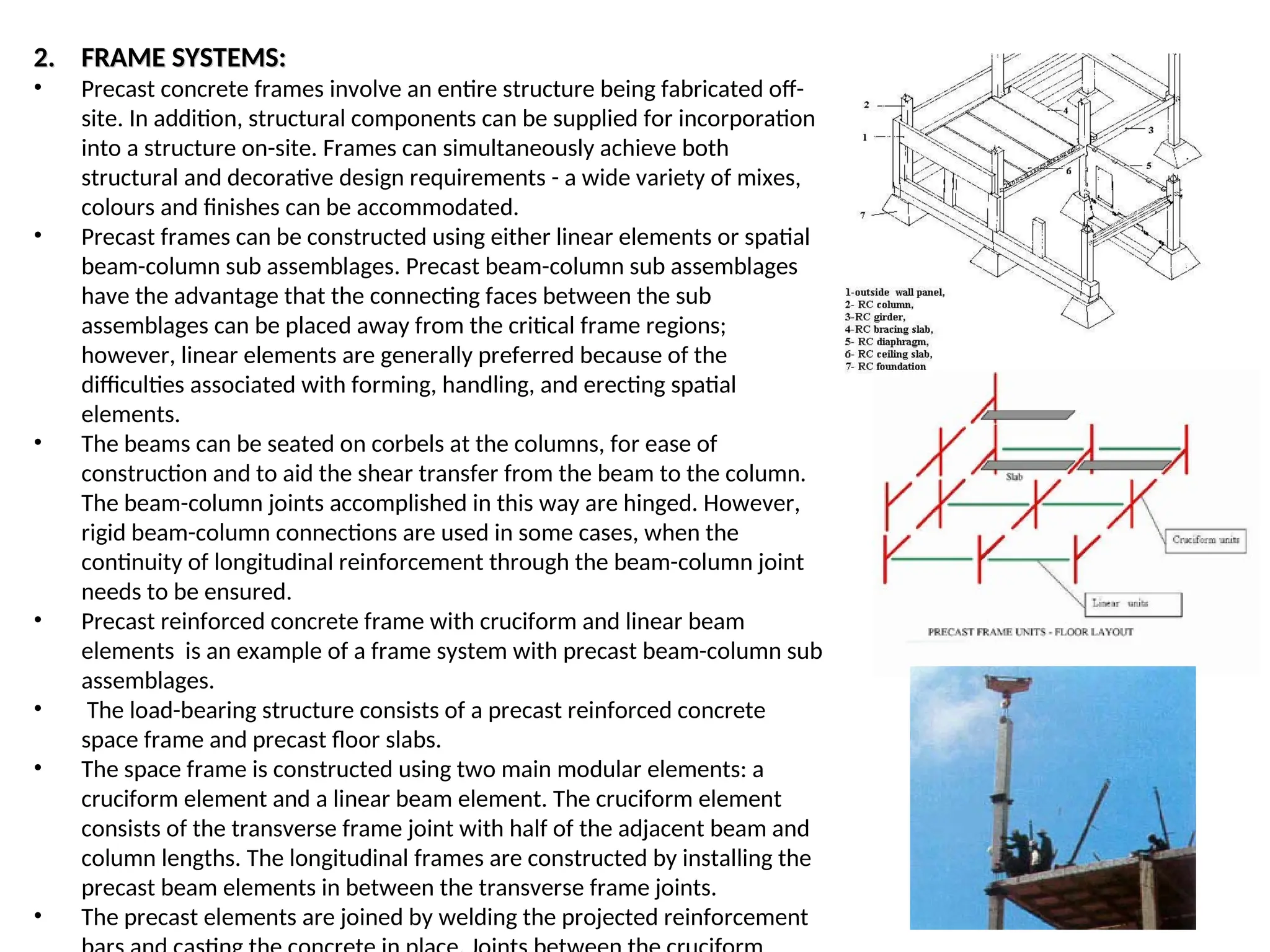
• Precast reinforced concrete frame with cruciform and linear beam
elements is an example of a frame system with precast beam-column sub
assemblages.
• The load-bearing structure consists of a precast reinforced concrete
space frame and precast floor slabs.
• The space frame is constructed using two main modular elements: a
cruciform element and a linear beam element. The cruciform element
consists of the transverse frame joint with half of the adjacent beam and
column lengths. The longitudinal frames are constructed by installing the
precast beam elements in between the transverse frame joints.
• The precast elements are joined by welding the projected reinforcement
7.
3.
3. SLAB-COLUMN SYSTEMSWITH SHEAR WALLS:
SLAB-COLUMN SYSTEMS WITH SHEAR WALLS:
• These systems rely on shear walls to sustain lateral load effects, whereas the
slab-column structure resists mainly gravity loads.
• There are two main systems in this category:
• Lift-slab system with walls
• Pre-stressed slab-column system
• The load-bearing structure consists of precast reinforced concrete columns
and slabs. Precast columns are usually two stories high.
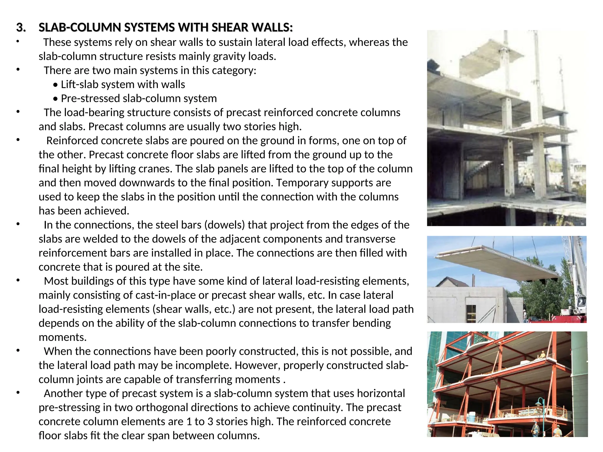
• Reinforced concrete slabs are poured on the ground in forms, one on top of
the other. Precast concrete floor slabs are lifted from the ground up to the
final height by lifting cranes. The slab panels are lifted to the top of the column
and then moved downwards to the final position. Temporary supports are
used to keep the slabs in the position until the connection with the columns
has been achieved.
• In the connections, the steel bars (dowels) that project from the edges of the
slabs are welded to the dowels of the adjacent components and transverse
reinforcement bars are installed in place. The connections are then filled with
concrete that is poured at the site.
• Most buildings of this type have some kind of lateral load-resisting elements,
mainly consisting of cast-in-place or precast shear walls, etc. In case lateral
load-resisting elements (shear walls, etc.) are not present, the lateral load path
depends on the ability of the slab-column connections to transfer bending
moments.
• When the connections have been poorly constructed, this is not possible, and
the lateral load path may be incomplete. However, properly constructed slab-
column joints are capable of transferring moments .
• Another type of precast system is a slab-column system that uses horizontal
pre-stressing in two orthogonal directions to achieve continuity. The precast
concrete column elements are 1 to 3 stories high. The reinforced concrete
floor slabs fit the clear span between columns.
8.
PRE - CASTSTRUCTURAL FLOOR AND ROOF SYSTEM
PRE - CAST STRUCTURAL FLOOR AND ROOF SYSTEM
1) HOLLOW CORE SLABS
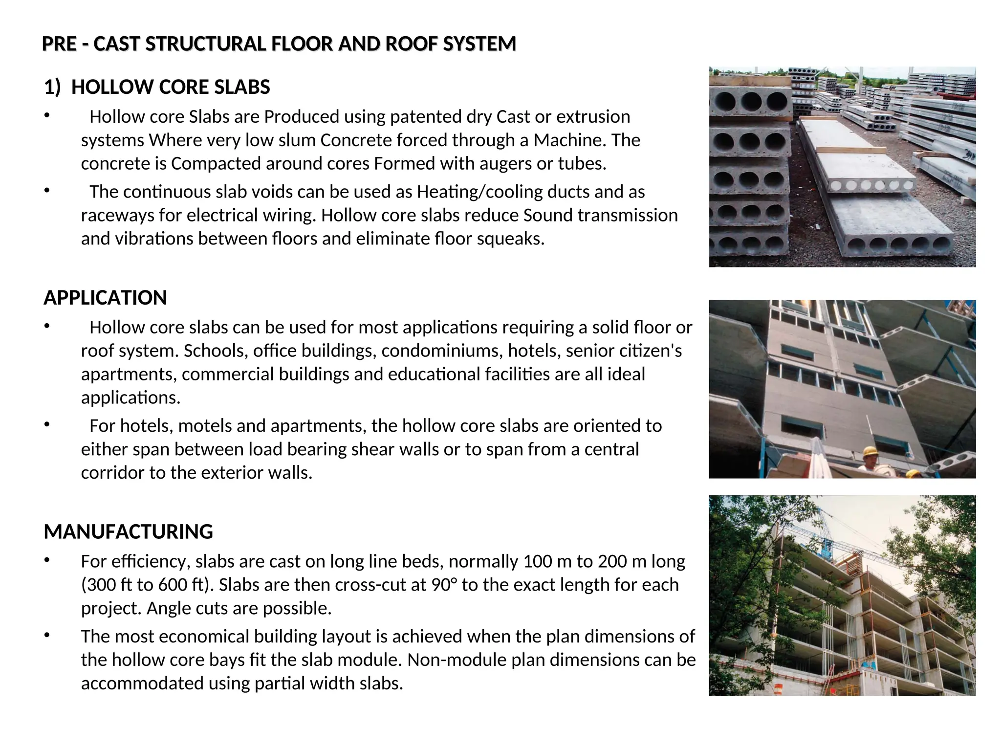
• Hollow core Slabs are Produced using patented dry Cast or extrusion
systems Where very low slum Concrete forced through a Machine. The
concrete is Compacted around cores Formed with augers or tubes.
• The continuous slab voids can be used as Heating/cooling ducts and as
raceways for electrical wiring. Hollow core slabs reduce Sound transmission
and vibrations between floors and eliminate floor squeaks.
APPLICATION
• Hollow core slabs can be used for most applications requiring a solid floor or
roof system. Schools, office buildings, condominiums, hotels, senior citizen's
apartments, commercial buildings and educational facilities are all ideal
applications.
• For hotels, motels and apartments, the hollow core slabs are oriented to
either span between load bearing shear walls or to span from a central
corridor to the exterior walls.
MANUFACTURING
• For efficiency, slabs are cast on long line beds, normally 100 m to 200 m long
(300 ft to 600 ft). Slabs are then cross-cut at 90° to the exact length for each
project. Angle cuts are possible.
• The most economical building layout is achieved when the plan dimensions of
the hollow core bays fit the slab module. Non-module plan dimensions can be
accommodated using partial width slabs.
9.
USE OF SLABVOIDS
• Hollow core slabs are cast with continuous voids to reduce cost and weight.
When properly coordinated for alignment, the voids in the hollow core can be
used as electrical or mechanical ducts.
• Thermal mass - slabs detailed to distribute heated air through the cores can
be used as the thermal mass in a passive solar application.
• Termodeck - the circular voids in precast concrete hollow core flooring and
roof slabs are connected to air-handling ducts, that constantly pump clean
fresh air into the building, expelling the old air, and radiating warm air in the
winter and cool air in the summer.
• Finished ceiling - hollow core, cast on smooth steel forms, has a finished
underside. The underside of slabs can be used as a finished ceiling as installed
by applying textured paint or an acoustical spray.
BEARING SUPPORTS FOR HOLLOW CORE
• Hollow core slabs can be supported on many types of structural systems
designed to carry the required dead and live loads.
• Precast beams, precast walls, poured concrete beams and walls, masonry
walls, insulated concrete forming system walls, wood and steel stud walls and
structural steel beams are all suitable for use as load bearing systems with
hollow core slabs .
• The minimum bearing width is 75 mm (3 in). Hollow core in double bearing
on a beam or wall will require at least a 150 mm (6 in) wide bearing surface.
• For bearing hollow core on wood walls, it is recommended that a steel stud
track plate be used at the top and bottom of all wood bearing walls in lieu of
the traditional wood double top plate and single bottom plate. This will
eliminate the possibility of wood top plate crushing under the weight of the
slabs and the cumulative shrinkage that occurs in a multi-storey wood stud
wall.
2) DOUBLE TEESLABS
2) DOUBLE TEE SLABS
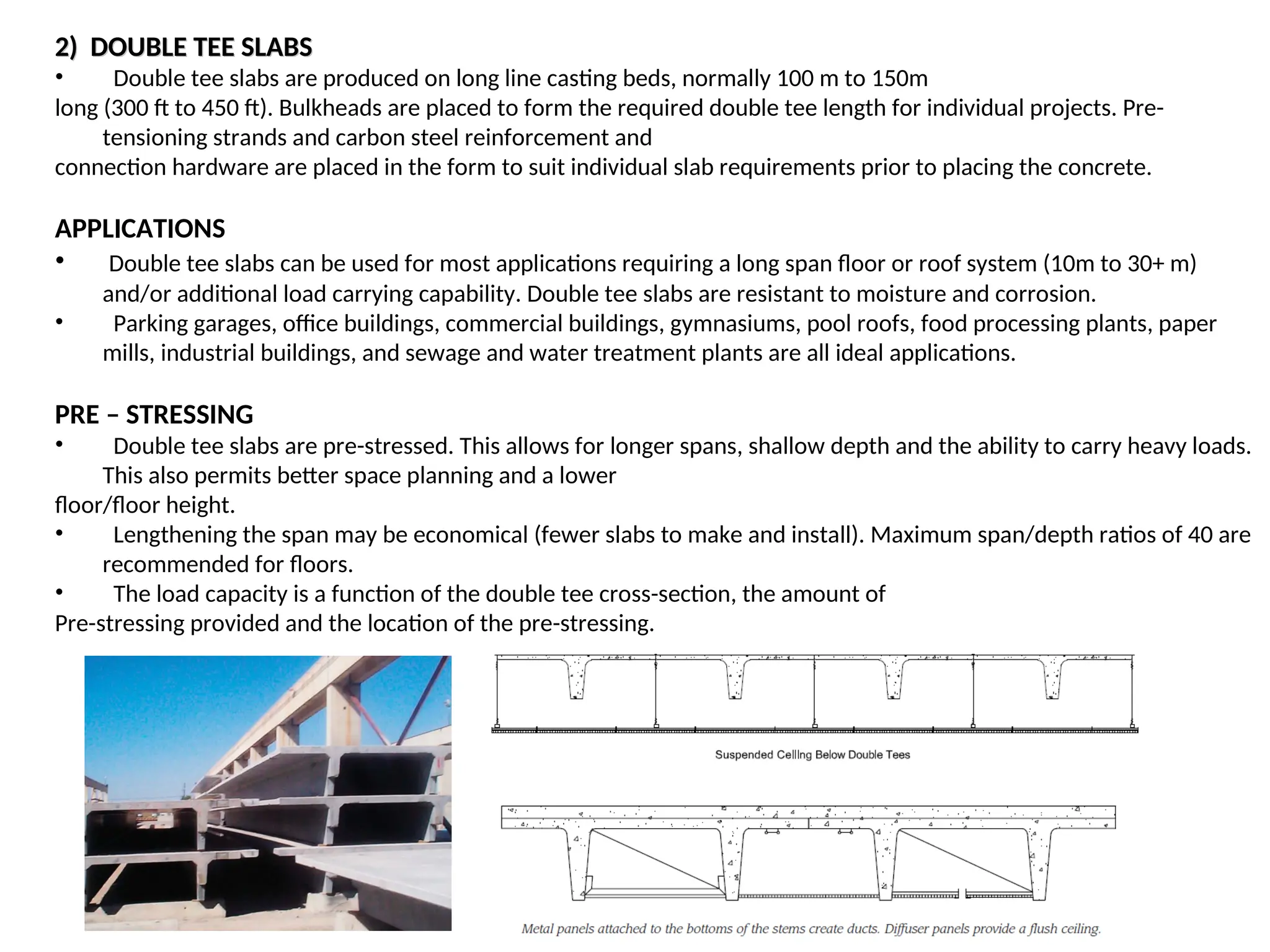
• Double tee slabs are produced on long line casting beds, normally 100 m to 150m
long (300 ft to 450 ft). Bulkheads are placed to form the required double tee length for individual projects. Pre-
tensioning strands and carbon steel reinforcement and
connection hardware are placed in the form to suit individual slab requirements prior to placing the concrete.
APPLICATIONS
• Double tee slabs can be used for most applications requiring a long span floor or roof system (10m to 30+ m)
and/or additional load carrying capability. Double tee slabs are resistant to moisture and corrosion.
• Parking garages, office buildings, commercial buildings, gymnasiums, pool roofs, food processing plants, paper
mills, industrial buildings, and sewage and water treatment plants are all ideal applications.
PRE – STRESSING
• Double tee slabs are pre-stressed. This allows for longer spans, shallow depth and the ability to carry heavy loads.
This also permits better space planning and a lower
floor/floor height.
• Lengthening the span may be economical (fewer slabs to make and install). Maximum span/depth ratios of 40 are
recommended for floors.
• The load capacity is a function of the double tee cross-section, the amount of
Pre-stressing provided and the location of the pre-stressing.
12.
BEARING SUPPORTS FORDOUBLE TEE SLABS
BEARING SUPPORTS FOR DOUBLE TEE SLABS
• Double tee slabs can be supported on many types of supports designed to
carry the required dead and live loads. Precast beams, precast walls, poured
concrete beams and walls, masonry walls, insulated concrete forming system
walls and structural steel beams are all suitable for use with double tee slabs as
load bearing systems.
TOP SURFACE PREPARATION
• Untopped double tee slabs are generally used for roof applications and some
parking garage floors. The top surface of Untopped double tee slabs is screeded
off and finished with a wood float.
•Double tee floor slabs in buildings require a 50 mm to 75 mm cast-in place
topping depending on the floor loading and embedded conduit to be installed.
•The top surface of double tee slabs receiving concrete topping is rough
broomed to allow bonding of the topping to the double tees.
FIRE RESISTANCE
• Double tee slabs provide excellent fire resistance. Depending on slab
thickness and strand cover, fire ratings of 1 to 2 hour endurance can be readily
achieved. A fire rating is dependent on equivalent thickness for heat
transmission, concrete cover over the pre-stressing strands for strength and
end restraint.
13.
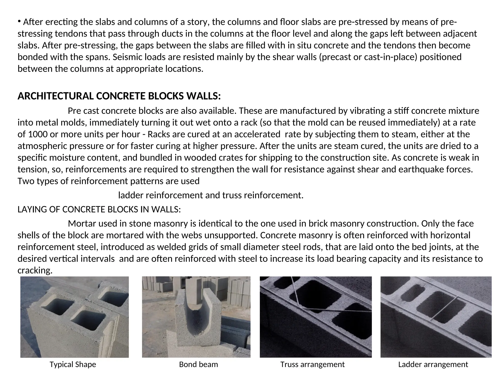
• After erectingthe slabs and columns of a story, the columns and floor slabs are pre-stressed by means of pre-
stressing tendons that pass through ducts in the columns at the floor level and along the gaps left between adjacent
slabs. After pre-stressing, the gaps between the slabs are filled with in situ concrete and the tendons then become
bonded with the spans. Seismic loads are resisted mainly by the shear walls (precast or cast-in-place) positioned
between the columns at appropriate locations.
ARCHITECTURAL CONCRETE BLOCKS WALLS:
Pre cast concrete blocks are also available. These are manufactured by vibrating a stiff concrete mixture
into metal molds, immediately turning it out wet onto a rack (so that the mold can be reused immediately) at a rate
of 1000 or more units per hour - Racks are cured at an accelerated rate by subjecting them to steam, either at the
atmospheric pressure or for faster curing at higher pressure. After the units are steam cured, the units are dried to a
specific moisture content, and bundled in wooded crates for shipping to the construction site. As concrete is weak in
tension, so, reinforcements are required to strengthen the wall for resistance against shear and earthquake forces.
Two types of reinforcement patterns are used
ladder reinforcement and truss reinforcement.
LAYING OF CONCRETE BLOCKS IN WALLS:
Mortar used in stone masonry is identical to the one used in brick masonry construction. Only the face
shells of the block are mortared with the webs unsupported. Concrete masonry is often reinforced with horizontal
reinforcement steel, introduced as welded grids of small diameter steel rods, that are laid onto the bed joints, at the
desired vertical intervals and are often reinforced with steel to increase its load bearing capacity and its resistance to
cracking.
Typical Shape Bond beam Truss arrangement Ladder arrangement
14.
PRODUCTION OF PRECASTCONCRETE
Precast concrete is produced on steel pallets. The production is done by a circulating system. Each precast
concrete part is produced individually.
1. DRAWING THE LAYING PLAN
• The walls and element slabs are designed on a CAD
system.
• These data are read by the host computer and
transformed into machine data.
• The host computer controls the complete system.
• The sheeting consists of steel
profiles, which bond on the
steel pallet by means of strong
magnets.
• The sheeting is set by a
sheeting robot.
15.
2. THE REINFORCEMENT
•The reinforcement is specially welded to size for each wide slab.
• The reinforcement is placed either manually or by means of machine.
• Electrical boxes, empty pipes etc, are placed manually.
3. THE CONCRETING
• The concrete is very precisely
distributed over the whole surface by the
concreting machine.
• The concrete is distributed in the right
quantity on the right place.
4. STORAGE IN THE DRYING ROOM
• The steel tables are stored in a drying
room.
• It is constantly kept at the correct
temperature with the exact relative
humidity, taking the required concrete
strength into account.
16.
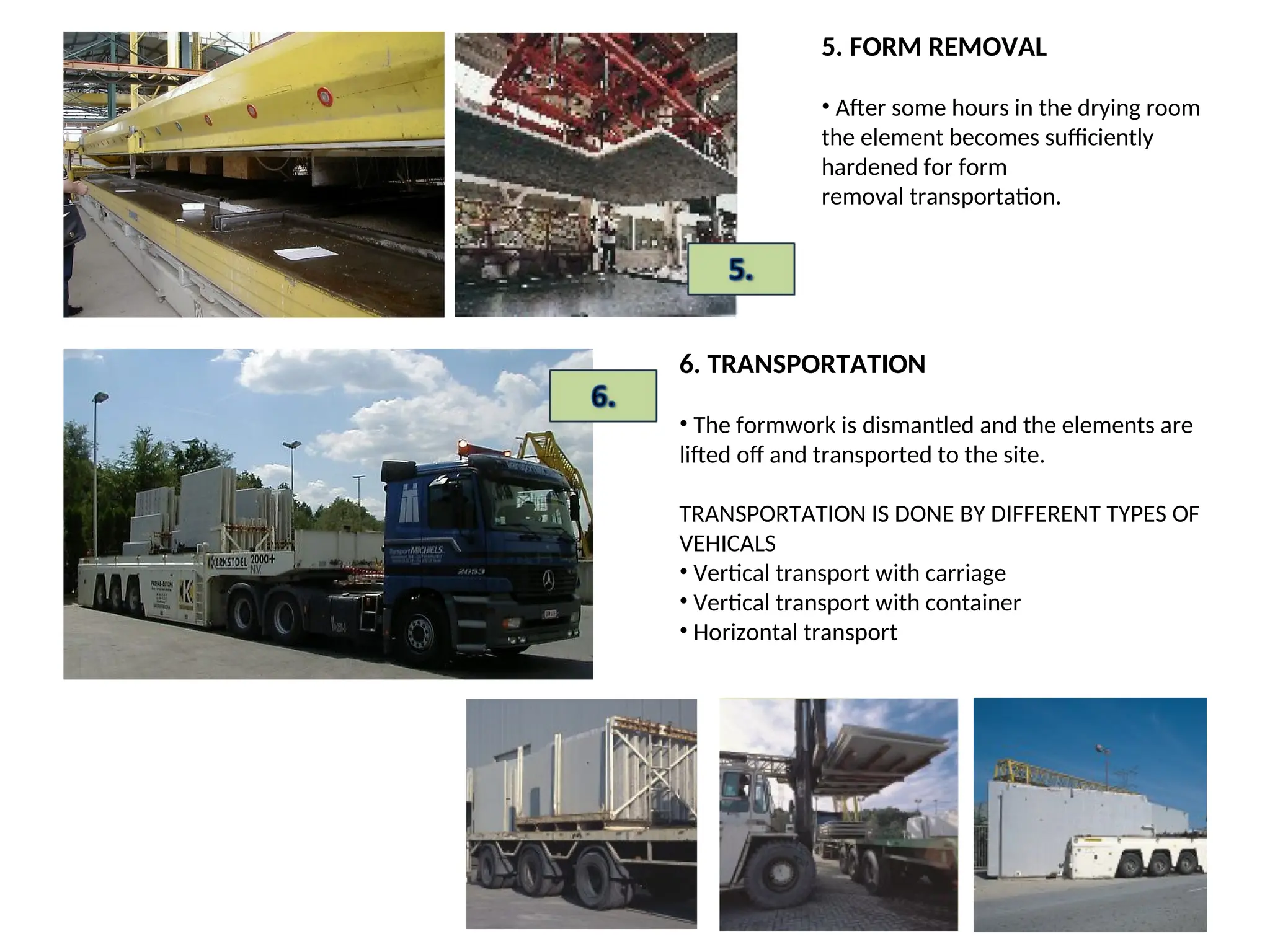
5. FORM REMOVAL
•After some hours in the drying room
the element becomes sufficiently
hardened for form
removal transportation.
6. TRANSPORTATION
• The formwork is dismantled and the elements are
lifted off and transported to the site.
TRANSPORTATION IS DONE BY DIFFERENT TYPES OF
VEHICALS
• Vertical transport with carriage
• Vertical transport with container
• Horizontal transport
17.
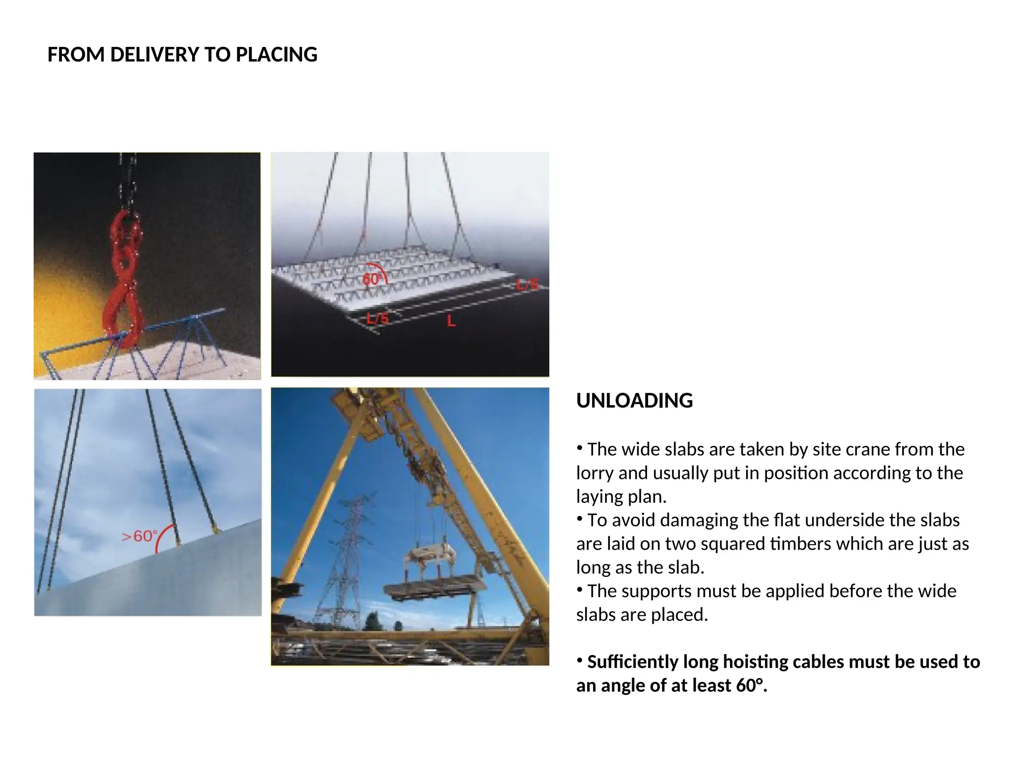
UNLOADING
• The wideslabs are taken by site crane from the
lorry and usually put in position according to the
laying plan.
• To avoid damaging the flat underside the slabs
are laid on two squared timbers which are just as
long as the slab.
• The supports must be applied before the wide
slabs are placed.
• Sufficiently long hoisting cables must be used to
an angle of at least 60°.
FROM DELIVERY TO PLACING
18.
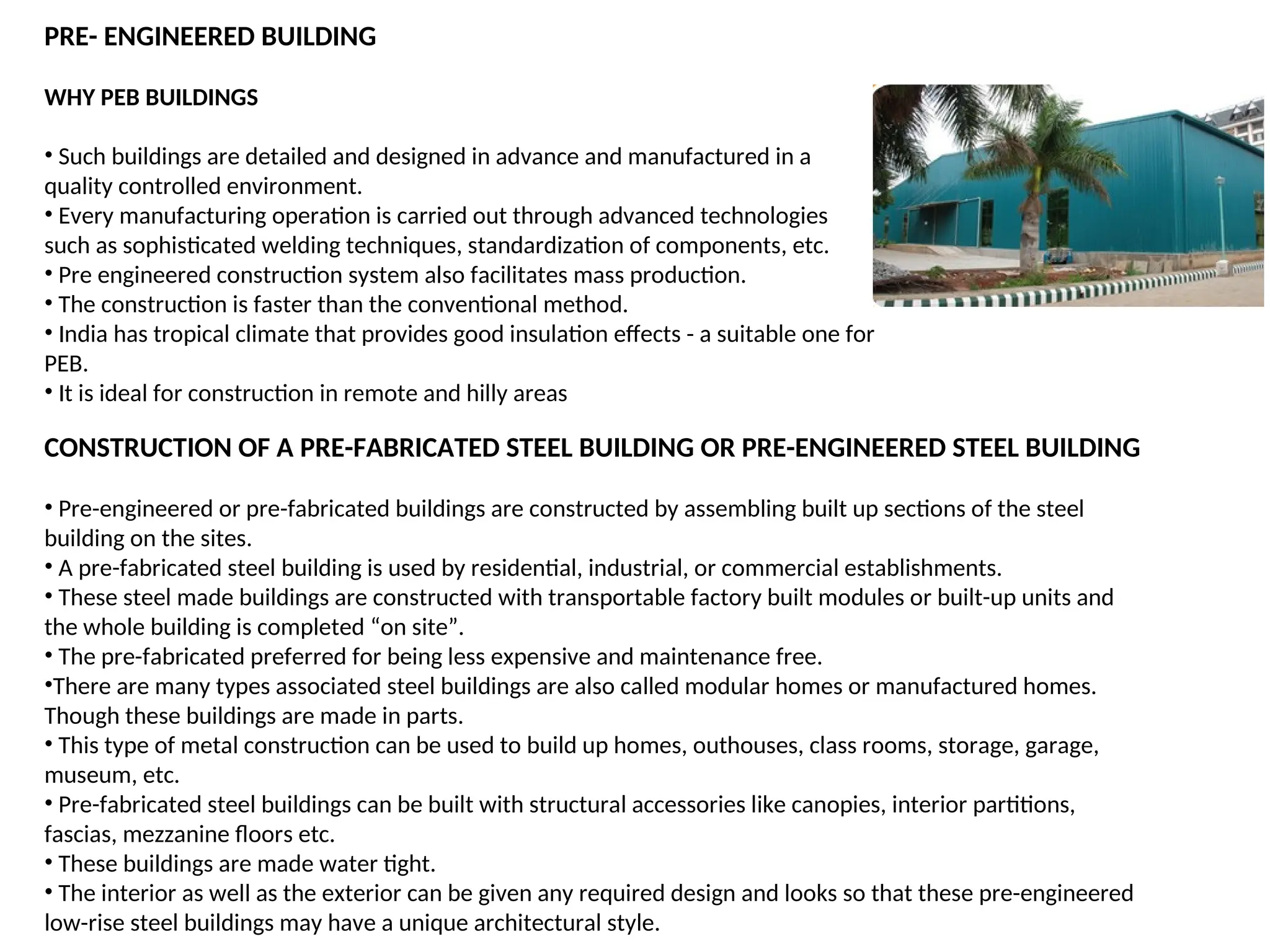
WHY PEB BUILDINGS
•Such buildings are detailed and designed in advance and manufactured in a
quality controlled environment.
• Every manufacturing operation is carried out through advanced technologies
such as sophisticated welding techniques, standardization of components, etc.
• Pre engineered construction system also facilitates mass production.
• The construction is faster than the conventional method.
• India has tropical climate that provides good insulation effects - a suitable one for
PEB.
• It is ideal for construction in remote and hilly areas
PRE- ENGINEERED BUILDING
CONSTRUCTION OF A PRE-FABRICATED STEEL BUILDING OR PRE-ENGINEERED STEEL BUILDING
• Pre-engineered or pre-fabricated buildings are constructed by assembling built up sections of the steel
building on the sites.
• A pre-fabricated steel building is used by residential, industrial, or commercial establishments.
• These steel made buildings are constructed with transportable factory built modules or built-up units and
the whole building is completed “on site”.
• The pre-fabricated preferred for being less expensive and maintenance free.
•There are many types associated steel buildings are also called modular homes or manufactured homes.
Though these buildings are made in parts.
• This type of metal construction can be used to build up homes, outhouses, class rooms, storage, garage,
museum, etc.
• Pre-fabricated steel buildings can be built with structural accessories like canopies, interior partitions,
fascias, mezzanine floors etc.
• These buildings are made water tight.
• The interior as well as the exterior can be given any required design and looks so that these pre-engineered
low-rise steel buildings may have a unique architectural style.
19.
The pre-fabricated steelbuildings are made of these components:
• Main framing or vertical columns for flooring,
• Purlins, grits, and eave struts for the painting and other finishing works,
• Sheeting and insulation or prefab panels used for false ceiling, and
• Brick and cement board walls for miscellaneous services.
The pre-fabricated steel buildings are of two types:
• Manufactured homes- buildings which are built by transporting and assembling of factory made modules on
the construction site. These are also called modular homes.
• Portable pre-engineered buildings- these steel buildings are made on wheels so that they can move from
place to place. These are called mobile homes.
20.
PRE-CAST CONCRETE PARTS
DESCRIPTIONOF THE BUILDING SYSTEM
• The various elements of a construction planned in in situ concrete in order to have them produced as pre-
cast concrete parts which, then, only need to be assembled at the construction site.
• This system is called "Pre-cast parts with in situ concrete finishing".
• After these parts have been assembled, the building they form is considered to be statically as worthy and
stable as constructions built monolithically.
• They are generally called 'pre-cast concrete parts'.
Office Building in Belgium
• Can be deconstructed any geometrical
element of a building into pre-cast
concrete parts and reassemble it at the
construction site.
• Area of application of such technology
is in residential and office buildings, etc.
21.
ADVANTAGES
• Building withpre-cast concrete elements opens up the opportunity to have a separate production because a
part of the required products can be stored ahead of time no matter at what stage the construction is.
• Pre-casting takes place in work sheds and therefore weather conditions are irrelevant.
• Pre-cast concrete parts have a different rate of production than at the construction site. One could therefore
stock supply and only deliver the amount required to the construction site.
•This production technology is extremely precise when it comes to measuring. As a result, the usually
prescribed width of the fixed concrete layer can be reduced. The steel reinforcement can be built exactly to
requirement and therefore used optimally.
•The finished construction is built with a high level of precision.
22.
• Due toa so called "all round calculation" the normally statically required reinforcement can be completely
built and set into the concrete parts. As a consequence the time required to process reinforcement material at
the construction site is reduced.
• Transporting the pre-cast concrete parts to the construction site is easy. The measurements of most pre-cast
concrete parts often do not require the use of a long vehicle. Floor slab elements normally weigh about
130kg/m², double walls about 270kg/m².
• This technology could replace building with skeleton frameworks. The advantage lies in having smooth wall
and ceiling surfaces. Visible support structures are no longer required as they are incorporated within the
concrete part.
• Pre-cast concrete parts replace formwork at the construction site as they themselves form the layer into
which in situ concrete is poured.
• The surface of the pre-cast concrete elements is smooth due to being produced in pallets (steel formwork).
Plastering is not required as very often the concrete surface is good enough for paint work.
23.
PLACING
• By bringingin of a new element the elements
already in position should not displaced or
damaged.
• The element should be placed in line and up to
the adjusting projections.
• The joints should be perpendicular.
• Two props on both sides are fixed on each
element.
• The crane hooks may only be removed after the
elements have been fixed in place and checked.
• Horizontal joints must be propped up and formed if necessary.
• Vertical joints must be formed if the joint is larger than 1 cm.
• Corners should be reinforced using angle bars or wooden planks. Props can be
used for T-joints.
• Concreting must take place in accordance with the conditions provided.
• The infill concrete must be properly vibrated.
24.
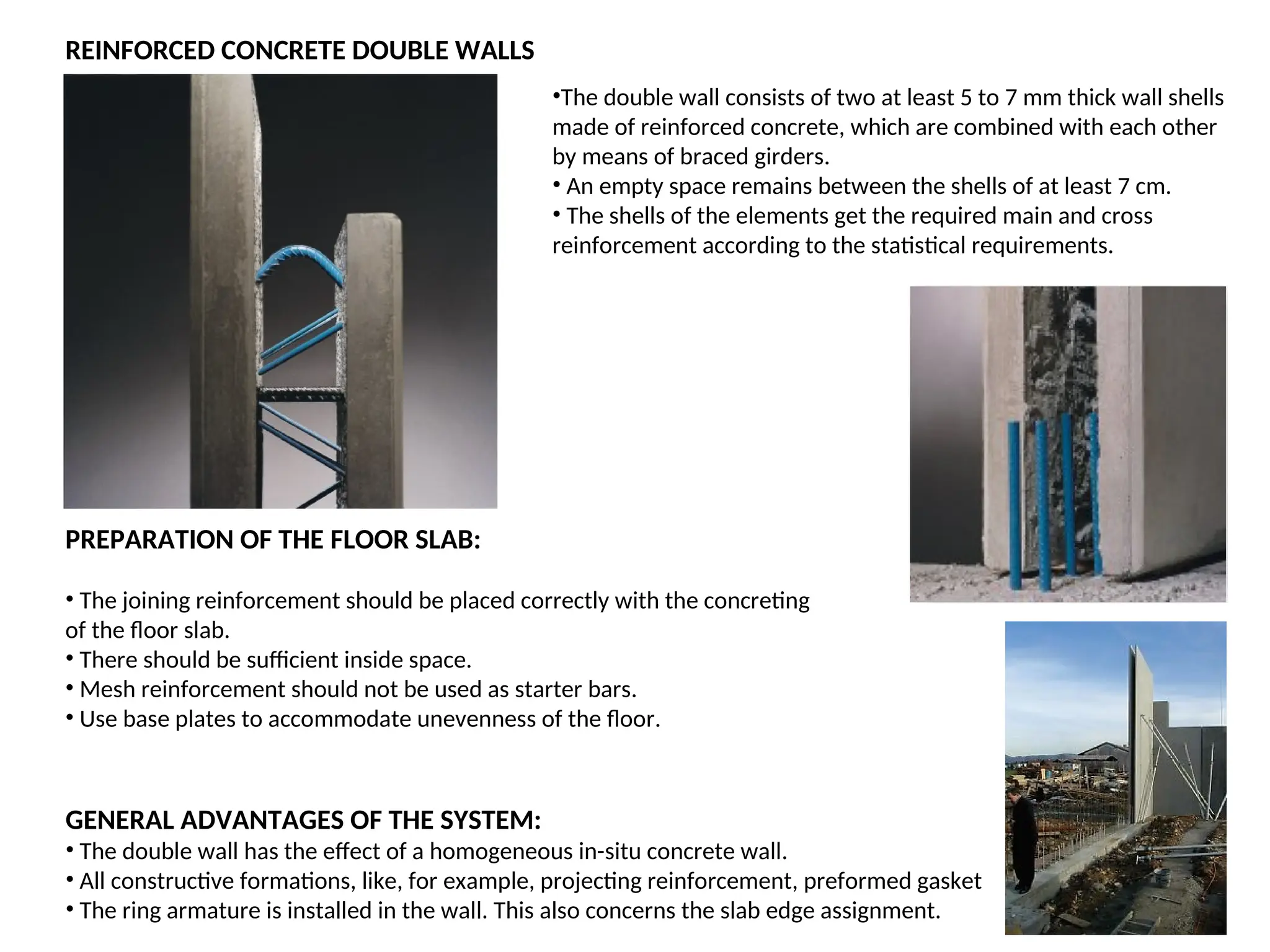
REINFORCED CONCRETE DOUBLEWALLS
PREPARATION OF THE FLOOR SLAB:
• The joining reinforcement should be placed correctly with the concreting
of the floor slab.
• There should be sufficient inside space.
• Mesh reinforcement should not be used as starter bars.
• Use base plates to accommodate unevenness of the floor.
•The double wall consists of two at least 5 to 7 mm thick wall shells
made of reinforced concrete, which are combined with each other
by means of braced girders.
• An empty space remains between the shells of at least 7 cm.
• The shells of the elements get the required main and cross
reinforcement according to the statistical requirements.
GENERAL ADVANTAGES OF THE SYSTEM:
• The double wall has the effect of a homogeneous in-situ concrete wall.
• All constructive formations, like, for example, projecting reinforcement, preformed gasket
• The ring armature is installed in the wall. This also concerns the slab edge assignment.
25.
JOINTS FOR DOUBLEWALL
Ceiling joints Base joints
VERTICAL JOINTS
Inner sealing outer sealing
Corner joints For double wall joints
26.
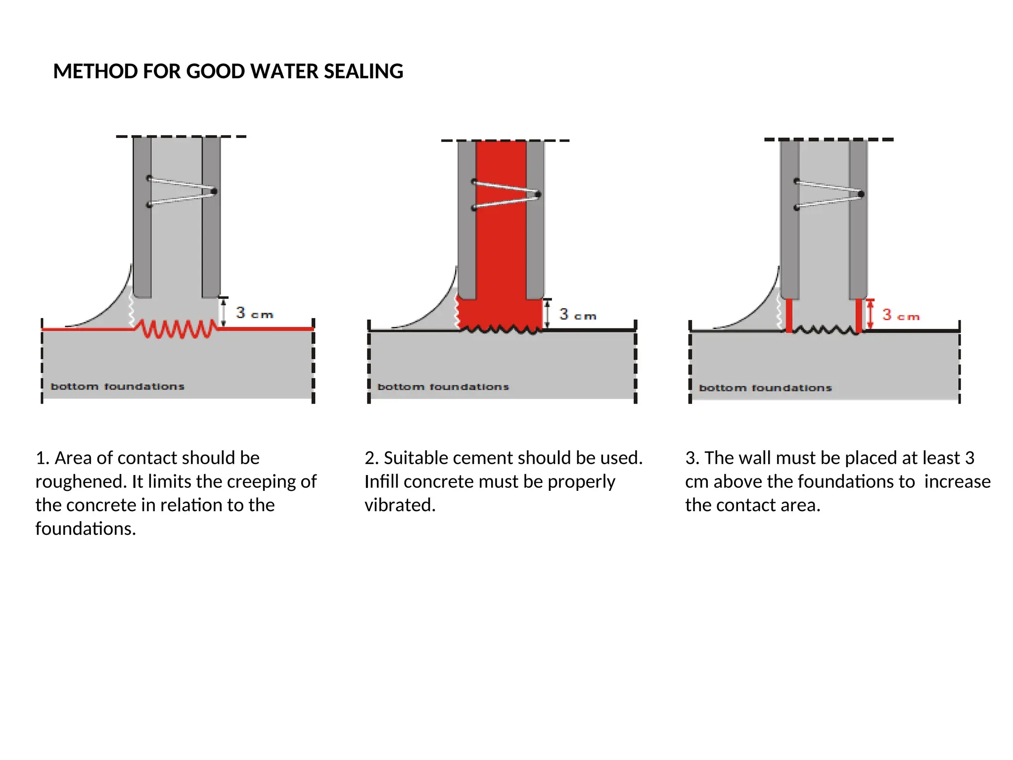
1. Area ofcontact should be
roughened. It limits the creeping of
the concrete in relation to the
foundations.
METHOD FOR GOOD WATER SEALING
2. Suitable cement should be used.
Infill concrete must be properly
vibrated.
3. The wall must be placed at least 3
cm above the foundations to increase
the contact area.
27.
METHOD OF ERECTINGA BUILDING USING
PRECONSTRUCTED MODULAR UNITS
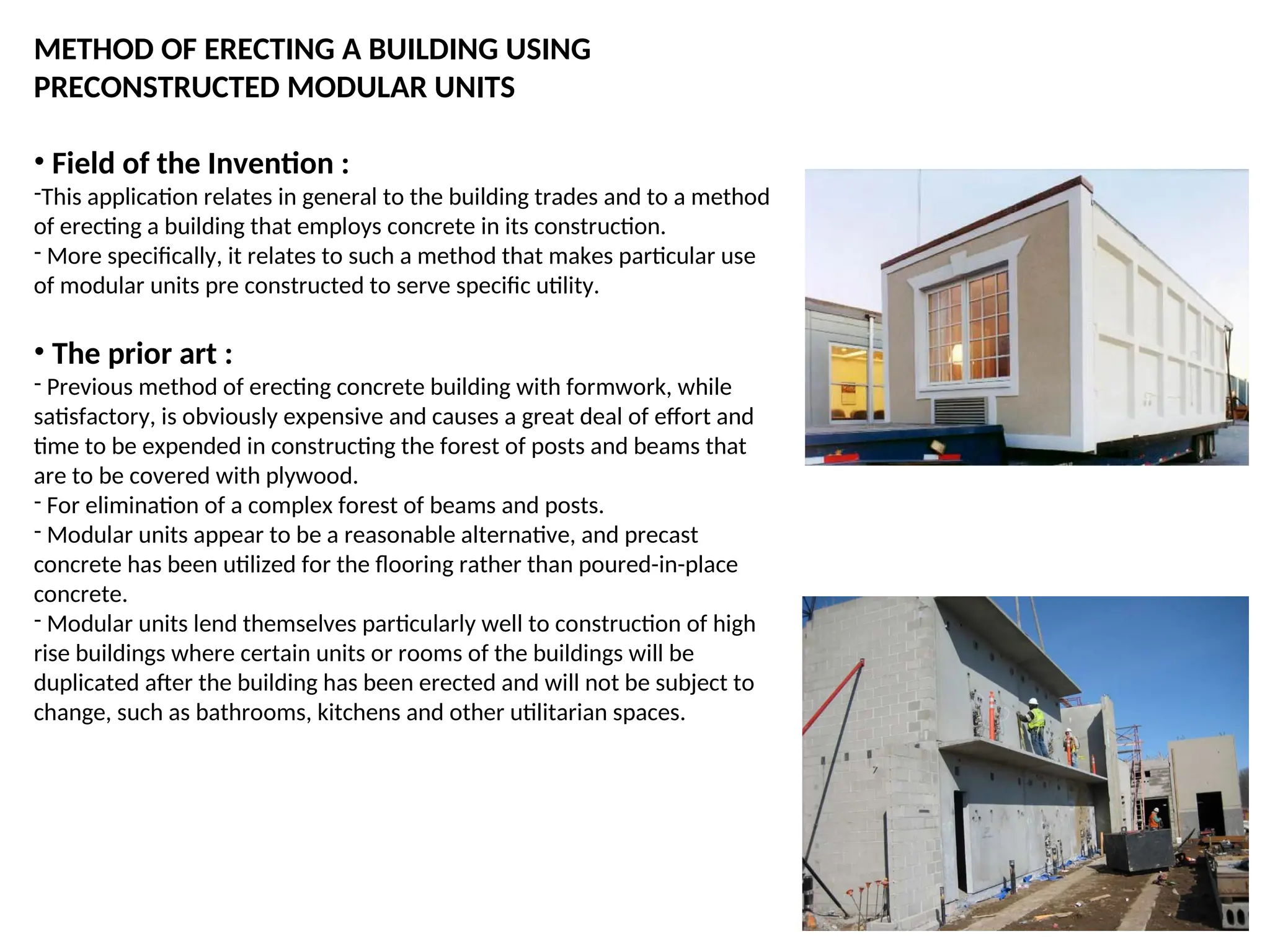
• Field of the Invention :
-This application relates in general to the building trades and to a method
of erecting a building that employs concrete in its construction.
- More specifically, it relates to such a method that makes particular use
of modular units pre constructed to serve specific utility.
• The prior art :
- Previous method of erecting concrete building with formwork, while
satisfactory, is obviously expensive and causes a great deal of effort and
time to be expended in constructing the forest of posts and beams that
are to be covered with plywood.
- For elimination of a complex forest of beams and posts.
- Modular units appear to be a reasonable alternative, and precast
concrete has been utilized for the flooring rather than poured-in-place
concrete.
- Modular units lend themselves particularly well to construction of high
rise buildings where certain units or rooms of the buildings will be
duplicated after the building has been erected and will not be subject to
change, such as bathrooms, kitchens and other utilitarian spaces.
28.
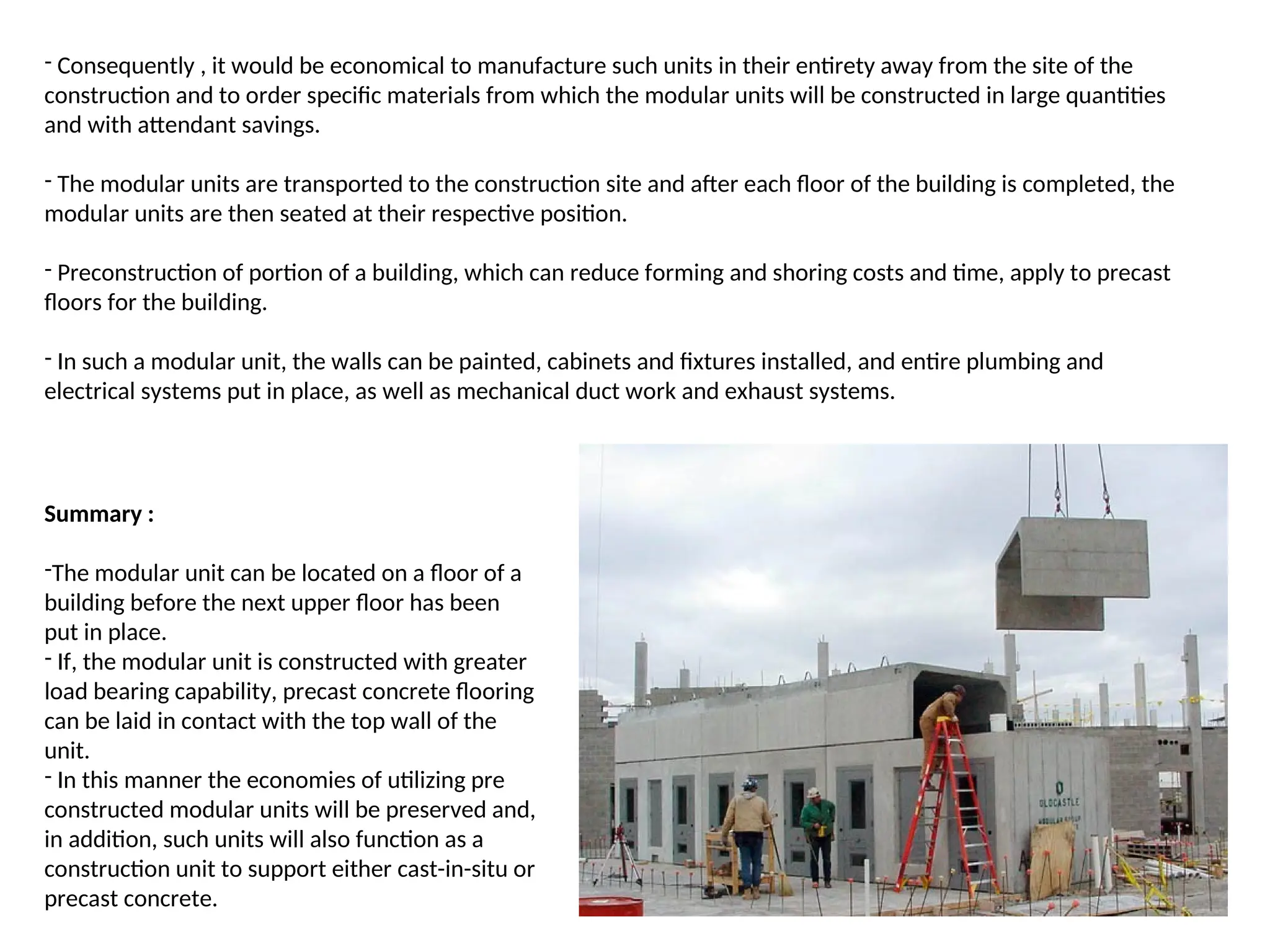
- Consequently ,it would be economical to manufacture such units in their entirety away from the site of the
construction and to order specific materials from which the modular units will be constructed in large quantities
and with attendant savings.
- The modular units are transported to the construction site and after each floor of the building is completed, the
modular units are then seated at their respective position.
- Preconstruction of portion of a building, which can reduce forming and shoring costs and time, apply to precast
floors for the building.
- In such a modular unit, the walls can be painted, cabinets and fixtures installed, and entire plumbing and
electrical systems put in place, as well as mechanical duct work and exhaust systems.
Summary :
-The modular unit can be located on a floor of a
building before the next upper floor has been
put in place.
- If, the modular unit is constructed with greater
load bearing capability, precast concrete flooring
can be laid in contact with the top wall of the
unit.
- In this manner the economies of utilizing pre
constructed modular units will be preserved and,
in addition, such units will also function as a
construction unit to support either cast-in-situ or
precast concrete.
29.
MODULAR BUILDING TYPES:
Aluminum buildings are fabricated from low maintenance, lightweight corrosive resistant aluminum. Their
convenience is their durability and flexibility in size and use.
Booth manufacturers construct portable enclosed steel structures for applications such as security, revenue and/or
access control booths or gate houses.
Building systems assemble prefabricated parts to construct permanent buildings.
Bullet-proof structures meet standards for resisting impact from bullets and other fast moving/high powered
objects.
Guardhouses are often placed at entrances to secure areas and serve as stations of clearance and general work
activity for security or admissions personnel. Sizes will vary by need.
Metal buildings are comprised mainly of select metal material and can be used for anything from storage to
protection in various sizes.
Portable buildings are buildings that can be easily moved or relocated. They are designed to be moved without
significant structural modification; examples include portable hospital facilities, classrooms, offices, etc.
Pre-engineered buildings are built of or with prefabricated sections or parts and are similar to prefabricated
structures in use and variety.
Prefab buildings are a type of modular building built with prefabricated parts.
Prefabricated buildings are different from modular buildings in that they are delivered fully assembled to site.
Sizes and uses are varying.
Prefabricated garages are modular structures often used to add on to a previously existing garage.
Steel buildings are fabricated primarily of steel and are often found in industrial settings as well as for outdoor use.
Size possibilities are unlimited.
Storage buildings can be made from prefabricated parts, usually those composed of steel materials.
Walk-in enclosures are enclosed areas, which can be entered and worked in. Guard houses, x-ray rooms and
communications rooms are examples of these.
30.
PRE CONSTRUCTED RESTROOMS :
• Savings of Up To 30% :
- This latest design concept is available in most floor plans, interior finishes, roof finishes, with
plumbing and electrical options, all at a savings of up to 30% below site-built restrooms.
- Available in natural block finish, or you can choose from a variety of paint colors. All of our block buildings come
with an anti-graffiti finish.
- Building is Fully relocatable to a New Site.
• General specifications :
- Foundation/Floor – Precast, 8” Moisture-Resistant Concrete Slab.
- Exterior Walls, and Finish – Split-Faced or Precision Block Exterior, Natural or Painted, with Anti-Graffiti Finish.
- Interior Restroom, Plumbing, Wall, and Finish – Welded, Structural, Galvanized Steel Frame. Finish
Options are 8”x 8”, Stone-Based Floor Tile with Epoxy Grout, or Continuous Corner-to-Corner, 3/32”, Class “A” FRP
(Creates a Shower Stall Effect).
- Ceiling – Structural Plank and Beam, or Structural Steel Frame with Wood Grain Fiber/Cement Painted Ceiling.
- Roof Finish – Standing Seam Metal, California Clay or Steel Roof Tiles, Concrete, or 40-Year Composition Shingles.
- Doors – 14, 16, or 18 gauge Steel, or Custom Stainless Steel Gates.
- Electrical – 100 AMP Service, Vandal Resistant, 24,000 Hour Light Fixtures, Concealed Switches and Outlets.
- Plumbing – Water Service, Custom Valve Combo with Cast Iron or PVC, DWV, and Stainless Steel Plumbing Fixtures.
32.
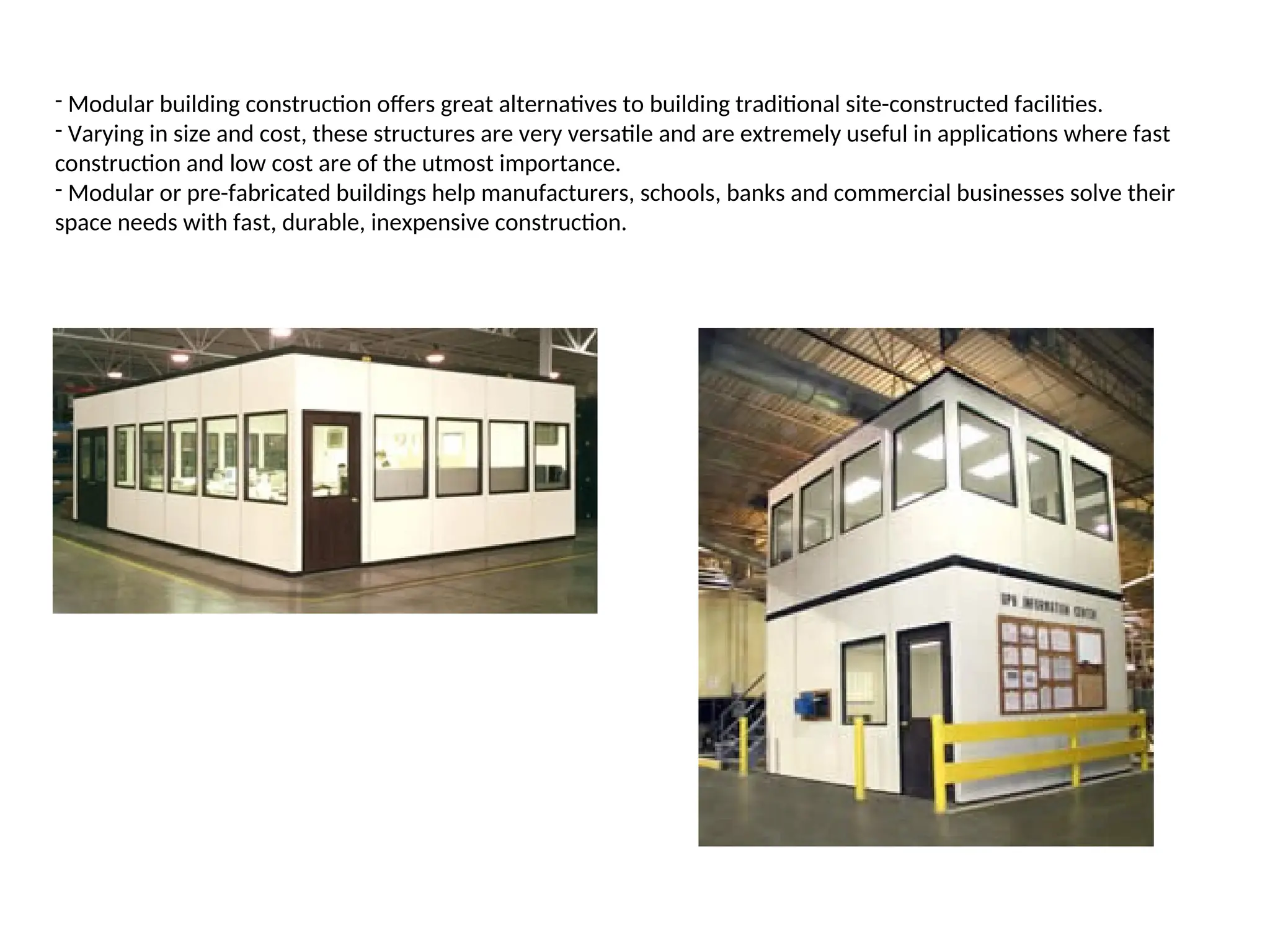
- Modular buildingconstruction offers great alternatives to building traditional site-constructed facilities.
- Varying in size and cost, these structures are very versatile and are extremely useful in applications where fast
construction and low cost are of the utmost importance.
- Modular or pre-fabricated buildings help manufacturers, schools, banks and commercial businesses solve their
space needs with fast, durable, inexpensive construction.
33.
INSULATION OF PRECASTELEMENTS :
• Insulation of the elements from outside :
- In this case the insulation is directly laid on the pallet in the works.
- After this the reinforcement is placed and the complete element is concreted.
- By doing this a fix connection between concrete and insulation is created.
• Insulation between the shells of the double wall :
- In this case first the reinforcement is placed on the pallet and then the element
is concreted.
- After the concreting process the insulation is pressed into the still wet
concrete.
-The free space between the braced girders is filled and the element is stored for
hardening.
- This element is the first shell of a double wall. In the further production process
the second shell is produced and by turning the first shell a double wall is
created.
- Here the insulation lies protected between
the two concrete shells.
• Advantages :
- The insulation is protected against damages and
weather conditions.
- With a wall, 300 mm thickness, and an insulation
thickness of 80 mm.
34.
ELEMENT SLAB :
-The element slab is a precast concrete slab with a statically supporting in situ concrete layer.
- The 4 to 6 cm thick, prefabricated concrete element contains a reinforcement in form of a braced girder which is
necessary for the assembly rigidity as well as the bending tensile reinforcement lengthwise and crosswise which is
necessary for the assembly and the final state.
- All later cutouts, slab cutouts, electrical boxes, drip noses, biases, mounting parts etc. are considered.
- The prefabricated slab element serves as formwork during the construction phase and is, after depositing and
hardening the in-situ concrete, jointly carrying as bulk cross section.
-In the final state, after hardening the in-situ concrete, the prefabricated slab with a statistically supporting in-situ
concrete layer is like a monolithically fabricated reinforced concrete slab.
- The precast element and the in-situ concrete is guaranteed by the specifically roughened surface during the
element production, which guarantees an optimal adhesion between element and concrete layer.
- The inserted compound and pushing reinforcement in form of braced girders ensures the interaction.
- All different kind of plans and weight loads are economically possible by a specific prefabrication.
- By the equality of the precast slab with statistically supporting in-situ concrete layer and the in-situ concrete slab
the requirements for 1) Fire signaling
2) Thermic protection
3) Sound proofing are identical.
- The valid regulations are applicable on element slabs without any difference.
35.
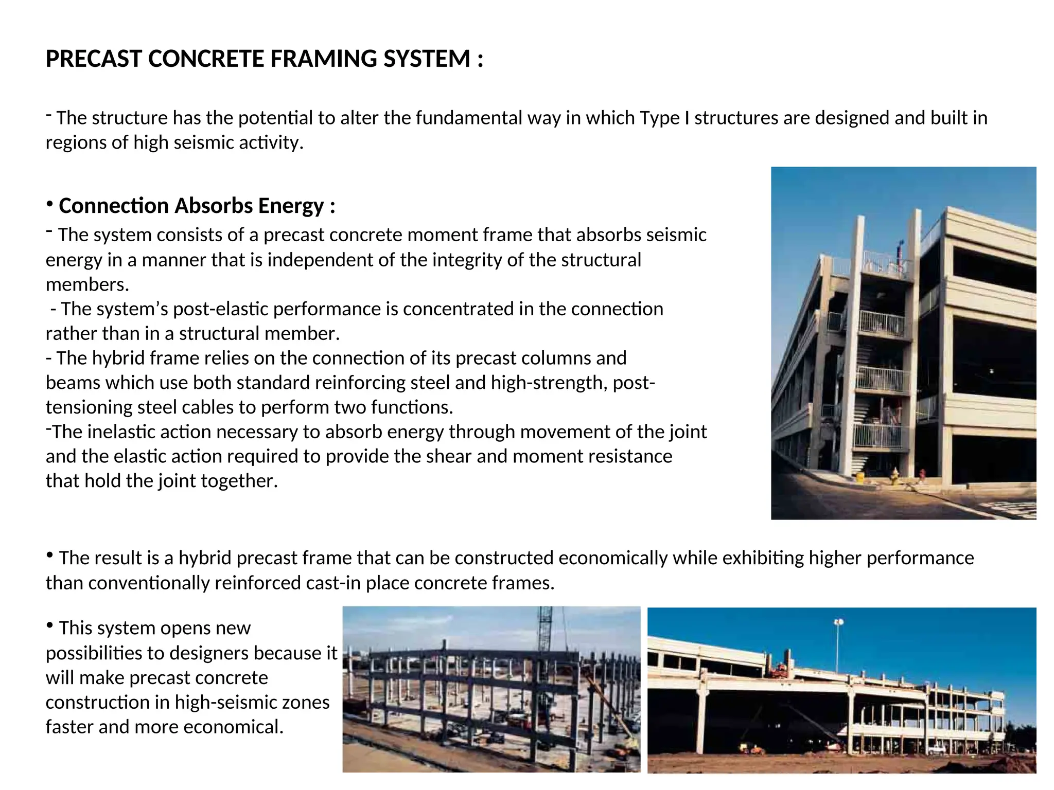
PRECAST CONCRETE FRAMINGSYSTEM :
- The structure has the potential to alter the fundamental way in which Type I structures are designed and built in
regions of high seismic activity.
• Connection Absorbs Energy :
- The system consists of a precast concrete moment frame that absorbs seismic
energy in a manner that is independent of the integrity of the structural
members.
- The system’s post-elastic performance is concentrated in the connection
rather than in a structural member.
- The hybrid frame relies on the connection of its precast columns and
beams which use both standard reinforcing steel and high-strength, post-
tensioning steel cables to perform two functions.
-The inelastic action necessary to absorb energy through movement of the joint
and the elastic action required to provide the shear and moment resistance
that hold the joint together.
• The result is a hybrid precast frame that can be constructed economically while exhibiting higher performance
than conventionally reinforced cast-in place concrete frames.
• This system opens new
possibilities to designers because it
will make precast concrete
construction in high-seismic zones
faster and more economical.
36.
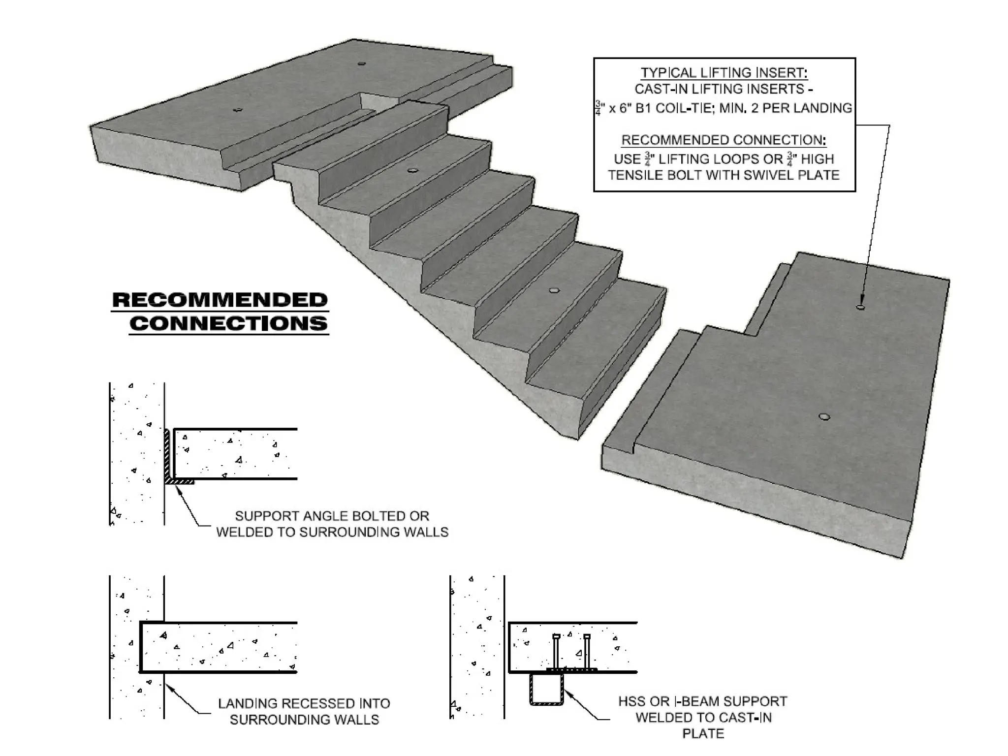
PRECAST STAIR ANDLANDING :
• Fabrication :
1. The steel forms shall be manufactured to produce raised non-slip continuous parallel ridges
near the tread nosing.
2. The underside of all precast stairs shall have a smooth trowel finish.
3. Accurately set reinforcing steel and weld at intersections. Vibrate continuously during
casting of concrete.
4. Bearing areas shall be reinforced against diagonal tension, splitting, rupture and flexure.
Extra ties, stirrups and reinforcing bars shall be placed at support points.
5. Cast in lifting devices required for erection of the precast concrete stair units. Ensure that
lifting devices used externally,
- or cast into units are capable of supporting the precast units in all positions that the units may be in during course
of manufacture, transportation and installation.
• Storage, Delivery, Handling and Protection :
1. Proper lifting devices for the stair units shall be incorporated to ensure that they will be
safely and efficiently handled and not produce distortion, cracking or deflection nor strain
or adversely affect the units.
2. Precast stair units shall be handled and adequately protected during fabrication, curing, storage and transport by
methods that will prevent damage, warping, cracking, breakage, chipping, staining or other disfigurement. Units
shall not be permitted to contact the earth or other staining influences.
3. Repair chipped, checked, cracked, blemished or defective units.
4. Precast stair units shall be delivered to the site clearly marked in an acceptable manner
as indicated on the Shop Drawings.
- Markings shall be on part of the unit which will not be exposed.
- The sequence of delivery to the site shall conform to an erection schedule.
- The timing of the delivery shall be scheduled to suit the storage space available and the
handling and erection operations.