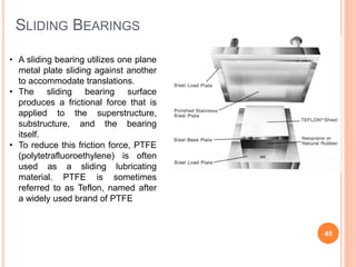
SlideShare a Scribd company logo
1 of 60
ANALYSIS & DESIGN OF
CABLE STAYED
BRIDGE
Supervisor :
Dr /Maher Moustafa El-abd1
INTRODUCTION
 Cables stretch diagonally between these pillars or towers
and the beam .These cables support the beam
 A cable-stayed bridge, one of the most modern bridges,
consists of a continuous strong beam (girder) with one or
more pillars or towers in the middle
 The cables are anchored in the tower rather than at the
end
2
ADVANTAGES OF CABLE STAYED BRIDGES
 much greater stiffness than the suspension bridge, so that
deformations of the deck under live loads are reduced
 can be constructed by cantilevering out from the tower -
the cables act both as temporary and permanent supports
to the bridge deck
 for a symmetrical bridge (i.e. spans on either side of the
tower are the same), the horizontal forces balance and
large ground anchorages are not required.
3
DIFFERENCE BETWEEN CABLE STAYED BRIDGE AND
CABLE SUSPENSION BRIDGE
 A multiple-tower cable-stayed bridge may appear similar to
a suspension bridge, but in fact is very different in principle and in
the method of construction.
 In the suspension bridge, a large cable hangs between two towers,
and is fastened at each end to anchorages in the ground or to a
massive structure.
 These cables form the primary load-bearing structure for the bridge
deck. Before the deck is installed, the cables are under tension from
only their own weight.
 Smaller cables or rods are then suspended from the main cable, and
used to support the load of the bridge deck, which is lifted in
sections and attached to the suspender cables.
 The tension on the cables must be transferred to the earth by the
anchorages, which are sometimes difficult to construct owing to
poor soil conditions. 4
COMPONENTS OF CABLE STAYED BRIDGE
5
LOAD TRANSMISSION
soil
piles
Pile cap
pylons
Cables
Deck
Tension
Compression
6
CLASSIFICATIONS
 Based on arrangements of the cables
• Radiating
• Harp
• Fan
• star
 Based on the shape of pylon
• A-type
• H-type
• Y-type
7
radial : cables connect evenly throughout the deck, but all
converge on the top of the pier
harp : cables are parallel, and evenly spaced along the
deck and the pier
fan : a combination of radial and harp types
star-shaped : cables are connected to two opposite
points on the pier
8
SHAPES OF PYLON
9
TYPES OF DECK
1. Twin I Girder
2. Truss girder
10
TYPES OF DECK
3. box girder
4. Orthotropic girder
11
CABLE
 A cable may be composed of one or more structural ropes,
structural strands, locked coil strands or parallel wire
strands.
 A strand is an assembly of wires formed helically around
centre wire in one or more symmetrical layers.
 A strand can be used either as an individual load-carrying
member, where radius or curvature is not a major
requirement, or as a component in the manufacture of the
structural rope.
 A rope is composed of a plurality of strands helically laid
around a core. In contrast to the strand, a rope provides
increased curvature capability and is used where curvature
of the cable becomes an important consideration.
12
TYPES OF CABLE
13
PROPERTIES OF CABLES
14
Cables are made of high-strength steel, usually encased in a
plastic or steel covering that is filled with grout , a fine
grained form of concrete, for protection against corrosion.
SELECTION OF CABLE CONFIGURATION
 The selection of cable configuration and number of cables
is dependent mainly on length of the span, type of
loadings, number of roadway lanes, height of towers, and
the designer’s individual sense of proportion and
aesthetics.
 Cost also plays important role in deciding the selection.
 Using less number of cables increases concentrated load at
a single point thereby requiring additional reinforcement
for the deck slab as well as pylon .
15
POSITIONS OF THE CABLES IN SPACE
 Two plane system
 Two Vertical Planes System
 Two Inclined Planes System
 The Single Plane System
16
TWO VERTICAL PLANES SYSTEM
 In this type of system there are two parallel sets of cables and the
tower on the either sides of the bridge, which lie in the same
vertical plane.
1. The cable anchorages may be situated outside the deck
structure, which is better than the other in terms of space as
no deck area of the deck surface is obstructed by the
presence of the cables and the towers.
2. but this requires substantial cantilevers to be constructed in
order to transfer the shear and the bending moment into the
deck structure.
 When the cables and tower lie within the cross-section of the
bridge, the area taken up cannot be utilized as a part of the
roadway and may be only partly used for the sidewalk. Thus as
area of the deck surface is made non-effective and has to be
compensated for by increasing overall width of the deck.
17
TWO INCLINED PLANES SYSTEM
 In this system the cables run from the edges of the bridge
deck to a point above the centreline of the bridge on an
A-shaped tower or λ-shaped or diamond shaped pylon.
 This arrangement can be recommended for very long
spans where the tower has to be very high and needs the
lateral stiffness given by the triangle and the frame
junction.
18
THE SINGLE PLANE SYSTEM
 This type of system consists of bridges with only one vertical
plane of stay cables along the middle longitudinal axis of the
superstructure
 As the cables are located in a single centre vertical strip thus all
the space is utilized by the traffic.
 This system also creates a lane separation as a natural
continuation of the highway approaches to the bridge.
 longitudinal arrangements of the cables used with two planes
bridges are also applied to single centre girder bridges.
19
CABLE ANCHORAGE
20
 Anchorage at concrete
CABLE ANCHORAGE
 Anchorage at concrete
21
22
CABLE ANCHORAGE
 Anchorage at steel
23
CABLE ANCHORAGE
 Anchorage at steel
24
CABLE ANCHORAGE
 Anchorage at steel
25
CABLE ANCHORAGE
 Anchorage at steel
26
INSTALLATION OF CABLES ANCHORAGE
1. Unreeling on carriages
2. Connecting the tensioning rod
3. Pulling into anchorage
4. Fixing the anchorage at the tower head
5. Installation at girder
6. Cable tensioning
7. Final anchorage
8. Delivery of strands
9. Supply PE pipes
10. Scaffolding at tower head
11. Anchor heads at the tower
12. Aligning PE pipes on bridge deck
13. Fusion welding of PE pipes
14. PE pipe with lifting collar
27
1. Strand pulled through the stay pipe
INSTALLATION OF CABLES ANCHORAGE
28
2. Temporary connection of the stay pipe at tower
INSTALLATION OF CABLES ANCHORAGE
29
3. Deformations influencing cable lengths
INSTALLATION OF CABLES ANCHORAGE
30
4. Mono jack for stressing individual strands
INSTALLATION OF CABLES ANCHORAGE
31
5. Stressing of individual strands
INSTALLATION OF CABLES ANCHORAGE
32
6. Stay cable without deviator and anti-vandalism pipe
INSTALLATION OF CABLES ANCHORAGE
33
7. Protruding strands for re-stressing
INSTALLATION OF CABLES ANCHORAGE
34
8. Multi-strand jack for stressing complete cable
INSTALLATION OF CABLES ANCHORAGE
35
9. Stressing of complete cable
INSTALLATION OF CABLES ANCHORAGE
36
10. Power seating of the wedges
INSTALLATION OF CABLES ANCHORAGE
37
11. Dampers inside boots
and anti-vandalism pipes
INSTALLATION OF CABLES ANCHORAGE
38
12. Corrosion-protection paint and strand cap
BRIDGE BEARINGS
39
FUNCTION OF BEARINGS
 Bridge bearings are used to transfer forces from the
superstructure to the substructure, allowing the following
types of movements of the superstructure:
 Translational movements; and
 Rotational movements
Until the middle of this century, the bearings used consisted
of following types:
 Pin
 Roller
 Rocker
 Metal sliding bearings
40
PIN BEARING
 A pin bearing is a type of fixed bearings that
accommodates rotations through the use of a steel
 Translational movements are not allowed.
 The pin at the top is composed of upper and lower
semicircularly recessed surfaces with a solid circular pin
placed between.
 Usually, there are caps at both ends of the pin to keep
the pin from sliding off the seats and to resist uplift loads
if required.
 The upper plate is connected to the sole plate by either
bolting or welding. The lower curved plate sits on the
masonry plate.
41
PIN BEARING
42
Steel Pin
• Rotational Movement is allowed
• Lateral and Translational Movements are Restricted
ROLLER TYPE BEARINGS
43
Multiple Roller BearingSingle Roller Bearing
o AASHTO requires that expansion rollers be equipped with “substantial
side bars” and be guided by gearing or other means to prevent lateral
movement, skewing, and creeping (AASHTO 10.29.3).
o A general drawback to this type of bearing is its tendency to collect dust
and debris.
ROCKER TYPE BEARING
44
• A rocker bearing is a type of expansion bearing that comes in a great
variety.
• It typically consists of a pin at the top that facilitates rotations, and a
curved surface at the bottom that accommodates the translational
movements
• Rocker and pin bearings are primarily used in steel bridges.
SLIDING BEARINGS
45
• A sliding bearing utilizes one plane
metal plate sliding against another
to accommodate translations.
• The sliding bearing surface
produces a frictional force that is
applied to the superstructure,
substructure, and the bearing
itself.
• To reduce this friction force, PTFE
(polytetrafluoroethylene) is often
used as a sliding lubricating
material. PTFE is sometimes
referred to as Teflon, named after
a widely used brand of PTFE
SLIDING BEARINGS
46
• Sliding Bearings be used alone
or more often used as a
component in other types of
bearings
• Pure sliding bearings can only
be used when the rotations
caused by the deflection at the
supports are negligible. They
are therefore limited to a span
length of 15 m or less by
ASHTTO [10.29.1.1]
KNUCKLE PINNED BEARING
47
• It is special form of Roller Bearing in which the
Knuckle pin is provided for easy rocking. A
knuckle pin is inserted between the top and
bottom casting. The top casting is attached to
the Bridge superstructure, while the bottom
casting rests on a series of rollers
• Knuckle pin bearing can accommodate large
movements and can accommodate sliding as
well as rotational movement
POT BEARINGS
48
POT BEARINGS
 A POT BEARING consists of a shallow steel cylinder, or
pot, on a vertical axis with a neoprene disk which is
slightly thinner than the cylinder and fitted tightly inside.
 A steel piston fits inside the cylinder and bears on the
neoprene.
 Flat brass rings are used to seal the rubber between the
piston and the pot.
 The rubber behaves like a viscous fluid flowing as
rotation may occur.
 Since the bearing will not resist bending moments, it
must be provided with an even bridge seat.
49
PLAIN ELASTOMERIC BEARINGS
50
LAMINATED ELASTOMERIC BEARINGS
51
Elastomeric material interspersed with steel
plates
LAMINATED ELASTOMERIC BEARINGS
52
o consist of a laminated
elastomeric bearing equipped
with a lead cylinder at the
center of the bearing.
o The function of the rubber-steel
laminated portion of the
bearing is to carry the weight of
the structure and provide post-
yield elasticity.
o The lead core is designed to
deform plastically, thereby
providing damping energy
dissipation.
o Lead rubber bearings are used
in seismically active areas
because of their performance
under earthquake loads.
SELECTION OF BEARING TYPE
ACCORDING TO AASHTO
53
Long Trans Long Trans Vert Long Trans Vert S L R U
L L S S L L L L 2 6 0 0 18
S S S S L L L L 4 4 0 0 20
U U U U U L L S 1 2 0 5 7
S S S S L L L S 5 3 0 0 21
S S U U S R R S 4 0 2 2 14
R R S S S R R S 4 0 4 0 16
R R U S U R R S 2 0 4 2 10
R R S S L S R S 4 1 3 0 17
R R S S U R R S 3 0 4 1 13
R R S S L S S S 5 1 2 0 19
S U U S U U R S 3 0 1 4 10
U U U S U S R S 3 0 1 4 10
S U U S U U R S 3 0 1 4 10
S U U U U U U S 2 0 0 6 6
Score Rank
Type of Bearing
S = suitable, U = unsuitable, L = suitable for limited applications, R = may be suitable, but requires special considerations or additional
elements such as slider or guideways.
Bearing Suitability:
Disk bearing
Pot bearing
Rocker bearing
AASHTO Table 14.6.2-1
Axis indicated
Single roller bearing
Multiple roller bearing
Rotation about bridge
Resistance to Loads
Curved sliding spherical
bearing
Curved sliding cylindrical
bearing
Double cylindrical bearing
Knuckle pinned bearing
Fiberglass reinforced pad
Cotton duck reinforced pad
Steel-reinforced elastomeric
bearing
Plane sliding bearing
Movement
Plain elastomeric pad
TESTS ON CABLE STAYED BRIDGE MODEL
54
1. Wind Tunnel Test
2. FatigueTest
3. TENSILE LOAD TEST OF THE STRAND
4. INSPECTION OF ANCHORAGES
5. CHECKING HARDNESS OF WEDGES
6. ROTATIVE FLEXION TEST
OUR PROJECT DEFINITION
 We have three spans (120+250+120) m
 The deck at the height of (50) m clearance
 We have (80) Cables are arranged in a double
plane over the bridge length with (12) m spacing.
55
COMPONENTS
1. Pylon
We have two non-prismatic pylons ,each one
have (130 m) height.
56
COMPONENTS
2. Deck
 Width = 28 m
 Consists of (6) lanes
 (3) lanes in each direction With width (3.6)m
 An intermediate island (1)m width
 (2) side walk each one (2.7)m width
57
COMPONENTS
2. Deck
 Consists of
 2 Main I girder 2.8 depth of thickness 2 cm and 2 flanges
60 cm width with thickness 5 cm.
 X-girders 2.8 depth of thickness 2 cm and 2 flanges 50 cm
width with thickness 5 cm.
 Stringers with IPE#600 section.
 Concrete Slab of thickness 20 cm Fcu=400 kg/cm2 and
7cm Bitumious asphalt. 58
COMPONENTS
3. Cables
 We have (10) cables in each side of the pylon.
 The cables have initial diameter (12)cm.
 The distance between cables in the deck plan equals to (12) m.
 The distance between them at its links to the pylon equals to (1.5) m
59
MODELING STEPS
(USING CSI SAP2000 PROGRAM )
60

More Related Content

What's hot (20)

Cable stayed ppt acp
Cable stayed ppt acpCable stayed ppt acp
Cable stayed ppt acp
 
Design of Multi-storey car parking
Design of Multi-storey car parkingDesign of Multi-storey car parking
Design of Multi-storey car parking
 
Shear wall
Shear wallShear wall
Shear wall
 
Ductile detailing
Ductile detailingDuctile detailing
Ductile detailing
 
Beams and columns
Beams and columns Beams and columns
Beams and columns
 
Types roof trusses
Types roof trussesTypes roof trusses
Types roof trusses
 
Slabs and types
Slabs and typesSlabs and types
Slabs and types
 
Pre-stressed Concrete
Pre-stressed ConcretePre-stressed Concrete
Pre-stressed Concrete
 
Watertank
WatertankWatertank
Watertank
 
Pre stressed concrete Bridge
Pre stressed concrete BridgePre stressed concrete Bridge
Pre stressed concrete Bridge
 
Flat slab ppt
Flat slab pptFlat slab ppt
Flat slab ppt
 
Design & Analysis of G+2 Residential Building Using STAAD Pro
Design & Analysis of G+2 Residential Building Using STAAD ProDesign & Analysis of G+2 Residential Building Using STAAD Pro
Design & Analysis of G+2 Residential Building Using STAAD Pro
 
Flat slab design
Flat slab designFlat slab design
Flat slab design
 
BALANCED CANTILEVER BRIDGE
BALANCED CANTILEVER BRIDGEBALANCED CANTILEVER BRIDGE
BALANCED CANTILEVER BRIDGE
 
Composite construction or Composite Structure/Frame
Composite construction or Composite Structure/FrameComposite construction or Composite Structure/Frame
Composite construction or Composite Structure/Frame
 
Raft foundations
Raft foundationsRaft foundations
Raft foundations
 
Steel connections
Steel connectionsSteel connections
Steel connections
 
Presentation on construction of cable stay bridge - a modern technique for su...
Presentation on construction of cable stay bridge - a modern technique for su...Presentation on construction of cable stay bridge - a modern technique for su...
Presentation on construction of cable stay bridge - a modern technique for su...
 
Design of compression members
Design of compression membersDesign of compression members
Design of compression members
 
Bearings in bridges
Bearings in bridgesBearings in bridges
Bearings in bridges
 

Similar to Cable-Stayed Bridge Design Analysis

Acm Space Frames
Acm Space FramesAcm Space Frames
Acm Space FramesAaqib Iqbal
 
CABLE ANCHORING AND GROUTING / Diaphragm Walls
CABLE ANCHORING AND GROUTING / Diaphragm Walls CABLE ANCHORING AND GROUTING / Diaphragm Walls
CABLE ANCHORING AND GROUTING / Diaphragm Walls Manvinder Kingra
 
Cable anchoring and grouting for cable tensioning
Cable anchoring and grouting for cable tensioningCable anchoring and grouting for cable tensioning
Cable anchoring and grouting for cable tensioningChinnuNinan
 
Cable strucutres(presentation)
Cable strucutres(presentation)Cable strucutres(presentation)
Cable strucutres(presentation)Waseem Akbar
 
Suspension-Bridge-dfsdfsfdsfsdppt sos.pptx
Suspension-Bridge-dfsdfsfdsfsdppt sos.pptxSuspension-Bridge-dfsdfsfdsfsdppt sos.pptx
Suspension-Bridge-dfsdfsfdsfsdppt sos.pptxsamratr1103
 
Calculation Note Final
Calculation Note FinalCalculation Note Final
Calculation Note FinalMohamed Elfike
 
Calculation note suez canal cable stayed bridge
Calculation note suez canal cable stayed bridgeCalculation note suez canal cable stayed bridge
Calculation note suez canal cable stayed bridgeMohammed Abdelkawy
 
Cable systems - form active structure system
Cable systems - form active structure systemCable systems - form active structure system
Cable systems - form active structure systemArchistudent Portal
 
CTP.ppt
CTP.pptCTP.ppt
CTP.pptarun t
 
Ch7 Box Girder Bridges (Steel Bridges تصميم الكباري المعدنية & Prof. Dr. Metw...
Ch7 Box Girder Bridges (Steel Bridges تصميم الكباري المعدنية & Prof. Dr. Metw...Ch7 Box Girder Bridges (Steel Bridges تصميم الكباري المعدنية & Prof. Dr. Metw...
Ch7 Box Girder Bridges (Steel Bridges تصميم الكباري المعدنية & Prof. Dr. Metw...Hossam Shafiq II
 
CHapter 1 introduction to bridge design eng
CHapter 1 introduction to bridge design engCHapter 1 introduction to bridge design eng
CHapter 1 introduction to bridge design engabdi beder
 
stress ribbon bridge.pptx
stress ribbon bridge.pptxstress ribbon bridge.pptx
stress ribbon bridge.pptxSauravShahane
 

Similar to Cable-Stayed Bridge Design Analysis (20)

Acm Space Frames
Acm Space FramesAcm Space Frames
Acm Space Frames
 
CABLE ANCHORING AND GROUTING / Diaphragm Walls
CABLE ANCHORING AND GROUTING / Diaphragm Walls CABLE ANCHORING AND GROUTING / Diaphragm Walls
CABLE ANCHORING AND GROUTING / Diaphragm Walls
 
Cable anchoring and grouting for cable tensioning
Cable anchoring and grouting for cable tensioningCable anchoring and grouting for cable tensioning
Cable anchoring and grouting for cable tensioning
 
Cable strucutres(presentation)
Cable strucutres(presentation)Cable strucutres(presentation)
Cable strucutres(presentation)
 
Suspension-Bridge-dfsdfsfdsfsdppt sos.pptx
Suspension-Bridge-dfsdfsfdsfsdppt sos.pptxSuspension-Bridge-dfsdfsfdsfsdppt sos.pptx
Suspension-Bridge-dfsdfsfdsfsdppt sos.pptx
 
Calculation Note Final
Calculation Note FinalCalculation Note Final
Calculation Note Final
 
Calculation note suez canal cable stayed bridge
Calculation note suez canal cable stayed bridgeCalculation note suez canal cable stayed bridge
Calculation note suez canal cable stayed bridge
 
Suspension bridge
Suspension bridge Suspension bridge
Suspension bridge
 
Cable systems - form active structure system
Cable systems - form active structure systemCable systems - form active structure system
Cable systems - form active structure system
 
CTP.ppt
CTP.pptCTP.ppt
CTP.ppt
 
Stress ribbon-bridges
Stress ribbon-bridgesStress ribbon-bridges
Stress ribbon-bridges
 
Bridge introduction
Bridge introductionBridge introduction
Bridge introduction
 
Ch7 Box Girder Bridges (Steel Bridges تصميم الكباري المعدنية & Prof. Dr. Metw...
Ch7 Box Girder Bridges (Steel Bridges تصميم الكباري المعدنية & Prof. Dr. Metw...Ch7 Box Girder Bridges (Steel Bridges تصميم الكباري المعدنية & Prof. Dr. Metw...
Ch7 Box Girder Bridges (Steel Bridges تصميم الكباري المعدنية & Prof. Dr. Metw...
 
Bridge intr.ppt
Bridge intr.pptBridge intr.ppt
Bridge intr.ppt
 
CHapter 1 introduction to bridge design eng
CHapter 1 introduction to bridge design engCHapter 1 introduction to bridge design eng
CHapter 1 introduction to bridge design eng
 
Bridge Engg1.ppt
Bridge Engg1.pptBridge Engg1.ppt
Bridge Engg1.ppt
 
Suspension bridges
Suspension bridgesSuspension bridges
Suspension bridges
 
stress ribbon bridge.pptx
stress ribbon bridge.pptxstress ribbon bridge.pptx
stress ribbon bridge.pptx
 
Form Active system
Form Active systemForm Active system
Form Active system
 
STRESS RIBBON BRIDGE
STRESS RIBBON BRIDGESTRESS RIBBON BRIDGE
STRESS RIBBON BRIDGE
 

Recently uploaded

Model Call Girl in Narela Delhi reach out to us at 🔝8264348440🔝
Model Call Girl in Narela Delhi reach out to us at 🔝8264348440🔝Model Call Girl in Narela Delhi reach out to us at 🔝8264348440🔝
Model Call Girl in Narela Delhi reach out to us at 🔝8264348440🔝soniya singh
 
VIP Call Girls Service Hitech City Hyderabad Call +91-8250192130
VIP Call Girls Service Hitech City Hyderabad Call +91-8250192130VIP Call Girls Service Hitech City Hyderabad Call +91-8250192130
VIP Call Girls Service Hitech City Hyderabad Call +91-8250192130Suhani Kapoor
 
Microscopic Analysis of Ceramic Materials.pptx
Microscopic Analysis of Ceramic Materials.pptxMicroscopic Analysis of Ceramic Materials.pptx
Microscopic Analysis of Ceramic Materials.pptxpurnimasatapathy1234
 
UNIT-V FMM.HYDRAULIC TURBINE - Construction and working
UNIT-V FMM.HYDRAULIC TURBINE - Construction and workingUNIT-V FMM.HYDRAULIC TURBINE - Construction and working
UNIT-V FMM.HYDRAULIC TURBINE - Construction and workingrknatarajan
 
Sheet Pile Wall Design and Construction: A Practical Guide for Civil Engineer...
Sheet Pile Wall Design and Construction: A Practical Guide for Civil Engineer...Sheet Pile Wall Design and Construction: A Practical Guide for Civil Engineer...
Sheet Pile Wall Design and Construction: A Practical Guide for Civil Engineer...Dr.Costas Sachpazis
 
Call Girls in Nagpur Suman Call 7001035870 Meet With Nagpur Escorts
Call Girls in Nagpur Suman Call 7001035870 Meet With Nagpur EscortsCall Girls in Nagpur Suman Call 7001035870 Meet With Nagpur Escorts
Call Girls in Nagpur Suman Call 7001035870 Meet With Nagpur EscortsCall Girls in Nagpur High Profile
 
College Call Girls Nashik Nehal 7001305949 Independent Escort Service Nashik
College Call Girls Nashik Nehal 7001305949 Independent Escort Service NashikCollege Call Girls Nashik Nehal 7001305949 Independent Escort Service Nashik
College Call Girls Nashik Nehal 7001305949 Independent Escort Service NashikCall Girls in Nagpur High Profile
 
the ladakh protest in leh ladakh 2024 sonam wangchuk.pptx
the ladakh protest in leh ladakh 2024 sonam wangchuk.pptxthe ladakh protest in leh ladakh 2024 sonam wangchuk.pptx
the ladakh protest in leh ladakh 2024 sonam wangchuk.pptxhumanexperienceaaa
 
Extrusion Processes and Their Limitations
Extrusion Processes and Their LimitationsExtrusion Processes and Their Limitations
Extrusion Processes and Their Limitations120cr0395
 
SPICE PARK APR2024 ( 6,793 SPICE Models )
SPICE PARK APR2024 ( 6,793 SPICE Models )SPICE PARK APR2024 ( 6,793 SPICE Models )
SPICE PARK APR2024 ( 6,793 SPICE Models )Tsuyoshi Horigome
 
Call Girls Service Nashik Vaishnavi 7001305949 Independent Escort Service Nashik
Call Girls Service Nashik Vaishnavi 7001305949 Independent Escort Service NashikCall Girls Service Nashik Vaishnavi 7001305949 Independent Escort Service Nashik
Call Girls Service Nashik Vaishnavi 7001305949 Independent Escort Service NashikCall Girls in Nagpur High Profile
 
Booking open Available Pune Call Girls Koregaon Park 6297143586 Call Hot Ind...
Booking open Available Pune Call Girls Koregaon Park  6297143586 Call Hot Ind...Booking open Available Pune Call Girls Koregaon Park  6297143586 Call Hot Ind...
Booking open Available Pune Call Girls Koregaon Park 6297143586 Call Hot Ind...Call Girls in Nagpur High Profile
 
VIP Call Girls Service Kondapur Hyderabad Call +91-8250192130
VIP Call Girls Service Kondapur Hyderabad Call +91-8250192130VIP Call Girls Service Kondapur Hyderabad Call +91-8250192130
VIP Call Girls Service Kondapur Hyderabad Call +91-8250192130Suhani Kapoor
 
Call Girls Service Nagpur Tanvi Call 7001035870 Meet With Nagpur Escorts
Call Girls Service Nagpur Tanvi Call 7001035870 Meet With Nagpur EscortsCall Girls Service Nagpur Tanvi Call 7001035870 Meet With Nagpur Escorts
Call Girls Service Nagpur Tanvi Call 7001035870 Meet With Nagpur EscortsCall Girls in Nagpur High Profile
 
(PRIYA) Rajgurunagar Call Girls Just Call 7001035870 [ Cash on Delivery ] Pun...
(PRIYA) Rajgurunagar Call Girls Just Call 7001035870 [ Cash on Delivery ] Pun...(PRIYA) Rajgurunagar Call Girls Just Call 7001035870 [ Cash on Delivery ] Pun...
(PRIYA) Rajgurunagar Call Girls Just Call 7001035870 [ Cash on Delivery ] Pun...ranjana rawat
 
HARDNESS, FRACTURE TOUGHNESS AND STRENGTH OF CERAMICS
HARDNESS, FRACTURE TOUGHNESS AND STRENGTH OF CERAMICSHARDNESS, FRACTURE TOUGHNESS AND STRENGTH OF CERAMICS
HARDNESS, FRACTURE TOUGHNESS AND STRENGTH OF CERAMICSRajkumarAkumalla
 
The Most Attractive Pune Call Girls Budhwar Peth 8250192130 Will You Miss Thi...
The Most Attractive Pune Call Girls Budhwar Peth 8250192130 Will You Miss Thi...The Most Attractive Pune Call Girls Budhwar Peth 8250192130 Will You Miss Thi...
The Most Attractive Pune Call Girls Budhwar Peth 8250192130 Will You Miss Thi...ranjana rawat
 
Introduction to Multiple Access Protocol.pptx
Introduction to Multiple Access Protocol.pptxIntroduction to Multiple Access Protocol.pptx
Introduction to Multiple Access Protocol.pptxupamatechverse
 

Recently uploaded (20)

Model Call Girl in Narela Delhi reach out to us at 🔝8264348440🔝
Model Call Girl in Narela Delhi reach out to us at 🔝8264348440🔝Model Call Girl in Narela Delhi reach out to us at 🔝8264348440🔝
Model Call Girl in Narela Delhi reach out to us at 🔝8264348440🔝
 
VIP Call Girls Service Hitech City Hyderabad Call +91-8250192130
VIP Call Girls Service Hitech City Hyderabad Call +91-8250192130VIP Call Girls Service Hitech City Hyderabad Call +91-8250192130
VIP Call Girls Service Hitech City Hyderabad Call +91-8250192130
 
Microscopic Analysis of Ceramic Materials.pptx
Microscopic Analysis of Ceramic Materials.pptxMicroscopic Analysis of Ceramic Materials.pptx
Microscopic Analysis of Ceramic Materials.pptx
 
UNIT-V FMM.HYDRAULIC TURBINE - Construction and working
UNIT-V FMM.HYDRAULIC TURBINE - Construction and workingUNIT-V FMM.HYDRAULIC TURBINE - Construction and working
UNIT-V FMM.HYDRAULIC TURBINE - Construction and working
 
Sheet Pile Wall Design and Construction: A Practical Guide for Civil Engineer...
Sheet Pile Wall Design and Construction: A Practical Guide for Civil Engineer...Sheet Pile Wall Design and Construction: A Practical Guide for Civil Engineer...
Sheet Pile Wall Design and Construction: A Practical Guide for Civil Engineer...
 
Call Girls in Nagpur Suman Call 7001035870 Meet With Nagpur Escorts
Call Girls in Nagpur Suman Call 7001035870 Meet With Nagpur EscortsCall Girls in Nagpur Suman Call 7001035870 Meet With Nagpur Escorts
Call Girls in Nagpur Suman Call 7001035870 Meet With Nagpur Escorts
 
College Call Girls Nashik Nehal 7001305949 Independent Escort Service Nashik
College Call Girls Nashik Nehal 7001305949 Independent Escort Service NashikCollege Call Girls Nashik Nehal 7001305949 Independent Escort Service Nashik
College Call Girls Nashik Nehal 7001305949 Independent Escort Service Nashik
 
the ladakh protest in leh ladakh 2024 sonam wangchuk.pptx
the ladakh protest in leh ladakh 2024 sonam wangchuk.pptxthe ladakh protest in leh ladakh 2024 sonam wangchuk.pptx
the ladakh protest in leh ladakh 2024 sonam wangchuk.pptx
 
Extrusion Processes and Their Limitations
Extrusion Processes and Their LimitationsExtrusion Processes and Their Limitations
Extrusion Processes and Their Limitations
 
SPICE PARK APR2024 ( 6,793 SPICE Models )
SPICE PARK APR2024 ( 6,793 SPICE Models )SPICE PARK APR2024 ( 6,793 SPICE Models )
SPICE PARK APR2024 ( 6,793 SPICE Models )
 
Call Girls Service Nashik Vaishnavi 7001305949 Independent Escort Service Nashik
Call Girls Service Nashik Vaishnavi 7001305949 Independent Escort Service NashikCall Girls Service Nashik Vaishnavi 7001305949 Independent Escort Service Nashik
Call Girls Service Nashik Vaishnavi 7001305949 Independent Escort Service Nashik
 
Booking open Available Pune Call Girls Koregaon Park 6297143586 Call Hot Ind...
Booking open Available Pune Call Girls Koregaon Park  6297143586 Call Hot Ind...Booking open Available Pune Call Girls Koregaon Park  6297143586 Call Hot Ind...
Booking open Available Pune Call Girls Koregaon Park 6297143586 Call Hot Ind...
 
VIP Call Girls Service Kondapur Hyderabad Call +91-8250192130
VIP Call Girls Service Kondapur Hyderabad Call +91-8250192130VIP Call Girls Service Kondapur Hyderabad Call +91-8250192130
VIP Call Girls Service Kondapur Hyderabad Call +91-8250192130
 
Call Girls Service Nagpur Tanvi Call 7001035870 Meet With Nagpur Escorts
Call Girls Service Nagpur Tanvi Call 7001035870 Meet With Nagpur EscortsCall Girls Service Nagpur Tanvi Call 7001035870 Meet With Nagpur Escorts
Call Girls Service Nagpur Tanvi Call 7001035870 Meet With Nagpur Escorts
 
(PRIYA) Rajgurunagar Call Girls Just Call 7001035870 [ Cash on Delivery ] Pun...
(PRIYA) Rajgurunagar Call Girls Just Call 7001035870 [ Cash on Delivery ] Pun...(PRIYA) Rajgurunagar Call Girls Just Call 7001035870 [ Cash on Delivery ] Pun...
(PRIYA) Rajgurunagar Call Girls Just Call 7001035870 [ Cash on Delivery ] Pun...
 
Call Us -/9953056974- Call Girls In Vikaspuri-/- Delhi NCR
Call Us -/9953056974- Call Girls In Vikaspuri-/- Delhi NCRCall Us -/9953056974- Call Girls In Vikaspuri-/- Delhi NCR
Call Us -/9953056974- Call Girls In Vikaspuri-/- Delhi NCR
 
9953056974 Call Girls In South Ex, Escorts (Delhi) NCR.pdf
9953056974 Call Girls In South Ex, Escorts (Delhi) NCR.pdf9953056974 Call Girls In South Ex, Escorts (Delhi) NCR.pdf
9953056974 Call Girls In South Ex, Escorts (Delhi) NCR.pdf
 
HARDNESS, FRACTURE TOUGHNESS AND STRENGTH OF CERAMICS
HARDNESS, FRACTURE TOUGHNESS AND STRENGTH OF CERAMICSHARDNESS, FRACTURE TOUGHNESS AND STRENGTH OF CERAMICS
HARDNESS, FRACTURE TOUGHNESS AND STRENGTH OF CERAMICS
 
The Most Attractive Pune Call Girls Budhwar Peth 8250192130 Will You Miss Thi...
The Most Attractive Pune Call Girls Budhwar Peth 8250192130 Will You Miss Thi...The Most Attractive Pune Call Girls Budhwar Peth 8250192130 Will You Miss Thi...
The Most Attractive Pune Call Girls Budhwar Peth 8250192130 Will You Miss Thi...
 
Introduction to Multiple Access Protocol.pptx
Introduction to Multiple Access Protocol.pptxIntroduction to Multiple Access Protocol.pptx
Introduction to Multiple Access Protocol.pptx
 

Cable-Stayed Bridge Design Analysis

  • 1. ANALYSIS & DESIGN OF CABLE STAYED BRIDGE Supervisor : Dr /Maher Moustafa El-abd1
  • 2. INTRODUCTION  Cables stretch diagonally between these pillars or towers and the beam .These cables support the beam  A cable-stayed bridge, one of the most modern bridges, consists of a continuous strong beam (girder) with one or more pillars or towers in the middle  The cables are anchored in the tower rather than at the end 2
  • 3. ADVANTAGES OF CABLE STAYED BRIDGES  much greater stiffness than the suspension bridge, so that deformations of the deck under live loads are reduced  can be constructed by cantilevering out from the tower - the cables act both as temporary and permanent supports to the bridge deck  for a symmetrical bridge (i.e. spans on either side of the tower are the same), the horizontal forces balance and large ground anchorages are not required. 3
  • 4. DIFFERENCE BETWEEN CABLE STAYED BRIDGE AND CABLE SUSPENSION BRIDGE  A multiple-tower cable-stayed bridge may appear similar to a suspension bridge, but in fact is very different in principle and in the method of construction.  In the suspension bridge, a large cable hangs between two towers, and is fastened at each end to anchorages in the ground or to a massive structure.  These cables form the primary load-bearing structure for the bridge deck. Before the deck is installed, the cables are under tension from only their own weight.  Smaller cables or rods are then suspended from the main cable, and used to support the load of the bridge deck, which is lifted in sections and attached to the suspender cables.  The tension on the cables must be transferred to the earth by the anchorages, which are sometimes difficult to construct owing to poor soil conditions. 4
  • 5. COMPONENTS OF CABLE STAYED BRIDGE 5
  • 7. CLASSIFICATIONS  Based on arrangements of the cables • Radiating • Harp • Fan • star  Based on the shape of pylon • A-type • H-type • Y-type 7
  • 8. radial : cables connect evenly throughout the deck, but all converge on the top of the pier harp : cables are parallel, and evenly spaced along the deck and the pier fan : a combination of radial and harp types star-shaped : cables are connected to two opposite points on the pier 8
  • 10. TYPES OF DECK 1. Twin I Girder 2. Truss girder 10
  • 11. TYPES OF DECK 3. box girder 4. Orthotropic girder 11
  • 12. CABLE  A cable may be composed of one or more structural ropes, structural strands, locked coil strands or parallel wire strands.  A strand is an assembly of wires formed helically around centre wire in one or more symmetrical layers.  A strand can be used either as an individual load-carrying member, where radius or curvature is not a major requirement, or as a component in the manufacture of the structural rope.  A rope is composed of a plurality of strands helically laid around a core. In contrast to the strand, a rope provides increased curvature capability and is used where curvature of the cable becomes an important consideration. 12
  • 14. 14 Cables are made of high-strength steel, usually encased in a plastic or steel covering that is filled with grout , a fine grained form of concrete, for protection against corrosion.
  • 15. SELECTION OF CABLE CONFIGURATION  The selection of cable configuration and number of cables is dependent mainly on length of the span, type of loadings, number of roadway lanes, height of towers, and the designer’s individual sense of proportion and aesthetics.  Cost also plays important role in deciding the selection.  Using less number of cables increases concentrated load at a single point thereby requiring additional reinforcement for the deck slab as well as pylon . 15
  • 16. POSITIONS OF THE CABLES IN SPACE  Two plane system  Two Vertical Planes System  Two Inclined Planes System  The Single Plane System 16
  • 17. TWO VERTICAL PLANES SYSTEM  In this type of system there are two parallel sets of cables and the tower on the either sides of the bridge, which lie in the same vertical plane. 1. The cable anchorages may be situated outside the deck structure, which is better than the other in terms of space as no deck area of the deck surface is obstructed by the presence of the cables and the towers. 2. but this requires substantial cantilevers to be constructed in order to transfer the shear and the bending moment into the deck structure.  When the cables and tower lie within the cross-section of the bridge, the area taken up cannot be utilized as a part of the roadway and may be only partly used for the sidewalk. Thus as area of the deck surface is made non-effective and has to be compensated for by increasing overall width of the deck. 17
  • 18. TWO INCLINED PLANES SYSTEM  In this system the cables run from the edges of the bridge deck to a point above the centreline of the bridge on an A-shaped tower or λ-shaped or diamond shaped pylon.  This arrangement can be recommended for very long spans where the tower has to be very high and needs the lateral stiffness given by the triangle and the frame junction. 18
  • 19. THE SINGLE PLANE SYSTEM  This type of system consists of bridges with only one vertical plane of stay cables along the middle longitudinal axis of the superstructure  As the cables are located in a single centre vertical strip thus all the space is utilized by the traffic.  This system also creates a lane separation as a natural continuation of the highway approaches to the bridge.  longitudinal arrangements of the cables used with two planes bridges are also applied to single centre girder bridges. 19
  • 26. 26 INSTALLATION OF CABLES ANCHORAGE 1. Unreeling on carriages 2. Connecting the tensioning rod 3. Pulling into anchorage 4. Fixing the anchorage at the tower head 5. Installation at girder 6. Cable tensioning 7. Final anchorage 8. Delivery of strands 9. Supply PE pipes 10. Scaffolding at tower head 11. Anchor heads at the tower 12. Aligning PE pipes on bridge deck 13. Fusion welding of PE pipes 14. PE pipe with lifting collar
  • 27. 27 1. Strand pulled through the stay pipe INSTALLATION OF CABLES ANCHORAGE
  • 28. 28 2. Temporary connection of the stay pipe at tower INSTALLATION OF CABLES ANCHORAGE
  • 29. INSTALLATION OF CABLES ANCHORAGE 29 3. Deformations influencing cable lengths
  • 30. INSTALLATION OF CABLES ANCHORAGE 30 4. Mono jack for stressing individual strands
  • 31. INSTALLATION OF CABLES ANCHORAGE 31 5. Stressing of individual strands
  • 32. INSTALLATION OF CABLES ANCHORAGE 32 6. Stay cable without deviator and anti-vandalism pipe
  • 33. INSTALLATION OF CABLES ANCHORAGE 33 7. Protruding strands for re-stressing
  • 34. INSTALLATION OF CABLES ANCHORAGE 34 8. Multi-strand jack for stressing complete cable
  • 35. INSTALLATION OF CABLES ANCHORAGE 35 9. Stressing of complete cable
  • 36. INSTALLATION OF CABLES ANCHORAGE 36 10. Power seating of the wedges
  • 37. INSTALLATION OF CABLES ANCHORAGE 37 11. Dampers inside boots and anti-vandalism pipes
  • 38. INSTALLATION OF CABLES ANCHORAGE 38 12. Corrosion-protection paint and strand cap
  • 40. FUNCTION OF BEARINGS  Bridge bearings are used to transfer forces from the superstructure to the substructure, allowing the following types of movements of the superstructure:  Translational movements; and  Rotational movements Until the middle of this century, the bearings used consisted of following types:  Pin  Roller  Rocker  Metal sliding bearings 40
  • 41. PIN BEARING  A pin bearing is a type of fixed bearings that accommodates rotations through the use of a steel  Translational movements are not allowed.  The pin at the top is composed of upper and lower semicircularly recessed surfaces with a solid circular pin placed between.  Usually, there are caps at both ends of the pin to keep the pin from sliding off the seats and to resist uplift loads if required.  The upper plate is connected to the sole plate by either bolting or welding. The lower curved plate sits on the masonry plate. 41
  • 42. PIN BEARING 42 Steel Pin • Rotational Movement is allowed • Lateral and Translational Movements are Restricted
  • 43. ROLLER TYPE BEARINGS 43 Multiple Roller BearingSingle Roller Bearing o AASHTO requires that expansion rollers be equipped with “substantial side bars” and be guided by gearing or other means to prevent lateral movement, skewing, and creeping (AASHTO 10.29.3). o A general drawback to this type of bearing is its tendency to collect dust and debris.
  • 44. ROCKER TYPE BEARING 44 • A rocker bearing is a type of expansion bearing that comes in a great variety. • It typically consists of a pin at the top that facilitates rotations, and a curved surface at the bottom that accommodates the translational movements • Rocker and pin bearings are primarily used in steel bridges.
  • 45. SLIDING BEARINGS 45 • A sliding bearing utilizes one plane metal plate sliding against another to accommodate translations. • The sliding bearing surface produces a frictional force that is applied to the superstructure, substructure, and the bearing itself. • To reduce this friction force, PTFE (polytetrafluoroethylene) is often used as a sliding lubricating material. PTFE is sometimes referred to as Teflon, named after a widely used brand of PTFE
  • 46. SLIDING BEARINGS 46 • Sliding Bearings be used alone or more often used as a component in other types of bearings • Pure sliding bearings can only be used when the rotations caused by the deflection at the supports are negligible. They are therefore limited to a span length of 15 m or less by ASHTTO [10.29.1.1]
  • 47. KNUCKLE PINNED BEARING 47 • It is special form of Roller Bearing in which the Knuckle pin is provided for easy rocking. A knuckle pin is inserted between the top and bottom casting. The top casting is attached to the Bridge superstructure, while the bottom casting rests on a series of rollers • Knuckle pin bearing can accommodate large movements and can accommodate sliding as well as rotational movement
  • 49. POT BEARINGS  A POT BEARING consists of a shallow steel cylinder, or pot, on a vertical axis with a neoprene disk which is slightly thinner than the cylinder and fitted tightly inside.  A steel piston fits inside the cylinder and bears on the neoprene.  Flat brass rings are used to seal the rubber between the piston and the pot.  The rubber behaves like a viscous fluid flowing as rotation may occur.  Since the bearing will not resist bending moments, it must be provided with an even bridge seat. 49
  • 51. LAMINATED ELASTOMERIC BEARINGS 51 Elastomeric material interspersed with steel plates
  • 52. LAMINATED ELASTOMERIC BEARINGS 52 o consist of a laminated elastomeric bearing equipped with a lead cylinder at the center of the bearing. o The function of the rubber-steel laminated portion of the bearing is to carry the weight of the structure and provide post- yield elasticity. o The lead core is designed to deform plastically, thereby providing damping energy dissipation. o Lead rubber bearings are used in seismically active areas because of their performance under earthquake loads.
  • 53. SELECTION OF BEARING TYPE ACCORDING TO AASHTO 53 Long Trans Long Trans Vert Long Trans Vert S L R U L L S S L L L L 2 6 0 0 18 S S S S L L L L 4 4 0 0 20 U U U U U L L S 1 2 0 5 7 S S S S L L L S 5 3 0 0 21 S S U U S R R S 4 0 2 2 14 R R S S S R R S 4 0 4 0 16 R R U S U R R S 2 0 4 2 10 R R S S L S R S 4 1 3 0 17 R R S S U R R S 3 0 4 1 13 R R S S L S S S 5 1 2 0 19 S U U S U U R S 3 0 1 4 10 U U U S U S R S 3 0 1 4 10 S U U S U U R S 3 0 1 4 10 S U U U U U U S 2 0 0 6 6 Score Rank Type of Bearing S = suitable, U = unsuitable, L = suitable for limited applications, R = may be suitable, but requires special considerations or additional elements such as slider or guideways. Bearing Suitability: Disk bearing Pot bearing Rocker bearing AASHTO Table 14.6.2-1 Axis indicated Single roller bearing Multiple roller bearing Rotation about bridge Resistance to Loads Curved sliding spherical bearing Curved sliding cylindrical bearing Double cylindrical bearing Knuckle pinned bearing Fiberglass reinforced pad Cotton duck reinforced pad Steel-reinforced elastomeric bearing Plane sliding bearing Movement Plain elastomeric pad
  • 54. TESTS ON CABLE STAYED BRIDGE MODEL 54 1. Wind Tunnel Test 2. FatigueTest 3. TENSILE LOAD TEST OF THE STRAND 4. INSPECTION OF ANCHORAGES 5. CHECKING HARDNESS OF WEDGES 6. ROTATIVE FLEXION TEST
  • 55. OUR PROJECT DEFINITION  We have three spans (120+250+120) m  The deck at the height of (50) m clearance  We have (80) Cables are arranged in a double plane over the bridge length with (12) m spacing. 55
  • 56. COMPONENTS 1. Pylon We have two non-prismatic pylons ,each one have (130 m) height. 56
  • 57. COMPONENTS 2. Deck  Width = 28 m  Consists of (6) lanes  (3) lanes in each direction With width (3.6)m  An intermediate island (1)m width  (2) side walk each one (2.7)m width 57
  • 58. COMPONENTS 2. Deck  Consists of  2 Main I girder 2.8 depth of thickness 2 cm and 2 flanges 60 cm width with thickness 5 cm.  X-girders 2.8 depth of thickness 2 cm and 2 flanges 50 cm width with thickness 5 cm.  Stringers with IPE#600 section.  Concrete Slab of thickness 20 cm Fcu=400 kg/cm2 and 7cm Bitumious asphalt. 58
  • 59. COMPONENTS 3. Cables  We have (10) cables in each side of the pylon.  The cables have initial diameter (12)cm.  The distance between cables in the deck plan equals to (12) m.  The distance between them at its links to the pylon equals to (1.5) m 59
  • 60. MODELING STEPS (USING CSI SAP2000 PROGRAM ) 60