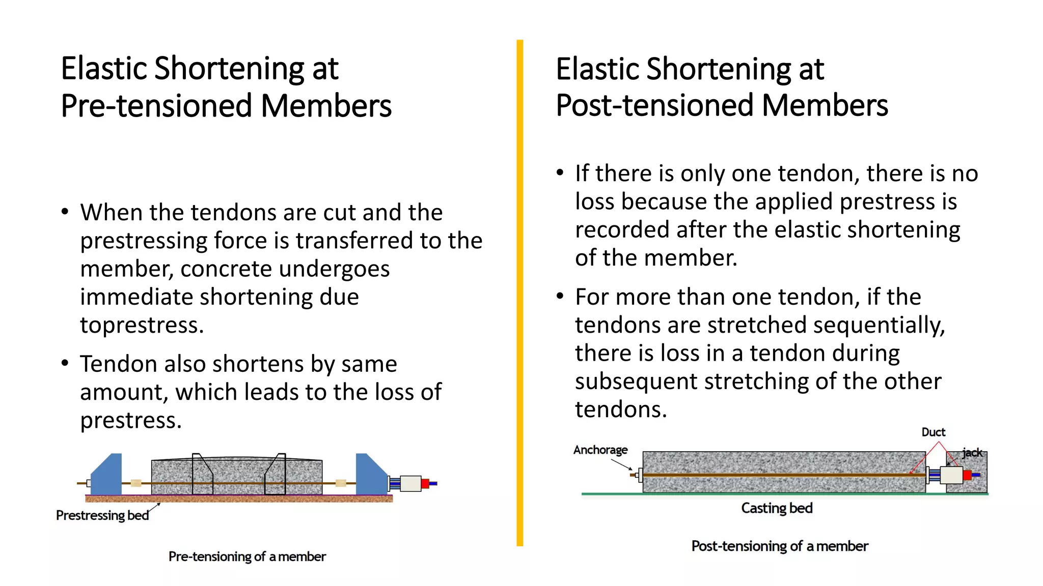
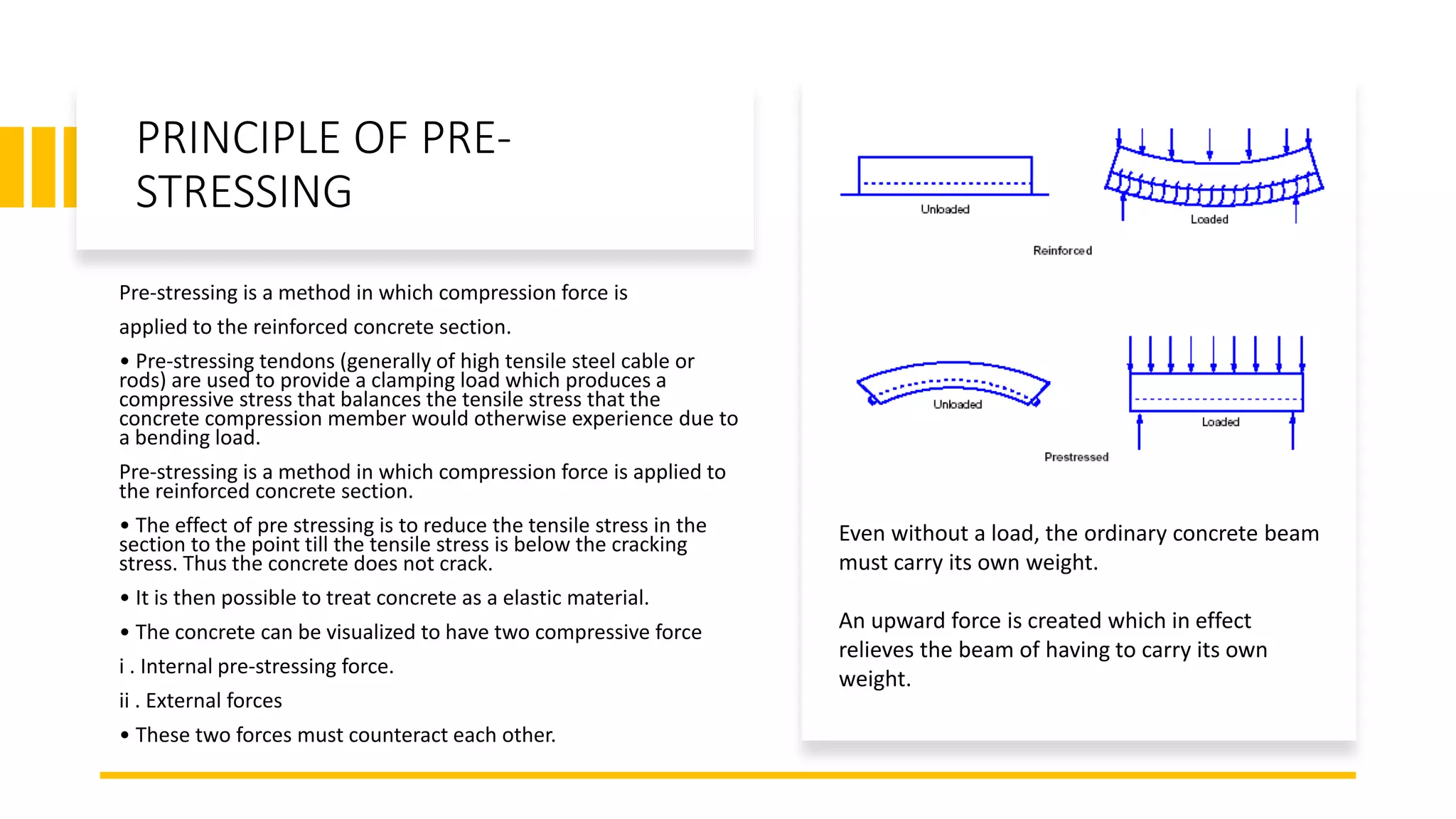
PRE - STRESSED
CONCRETE
ADVANCED BUILDING TECHNOLOGY AND SERVICES
AISHWARYA V SANAP
F Y M.ARCH - DR. D. Y. PATIL COLLEGE OF ARCHITECTURE
Introduction
Prestress is defined as a method of applying precompression to control the
stresses resulting due to external loads below the neutral axis of the beam
tension developed due to external load which is more than the permissible
limits of the plain concrete. Prestressed concrete is a method for overcoming
concrete's natural weakness in tension.
“Pre-stressed concrete is a form of reinforced concrete that builds in
compressive stresses during construction to oppose those found when in use.”
It is a combination of steel and concrete that takes advantages of the strengths
of each material.
• PRINCIPLE –
• Using high tensile strength steel alloys producing permanent pre-
compression in areas subjected to Tension. A portion of tensile stress is
counteracted thereby reducing the cross-sectional area of the steel
reinforcement
• METHODS :-
a) Pre-tensioning
b) Post-tensioning
• PRETENSIONING :- Placing of concrete around reinforcing tendons that have
been stressed to the desired degree.
• POST-TENSIONING :- Reinforcing tendons are stretched by jacks whilst
keeping them inserted in voids left prehandduring curing of concrete. These
spaces are then pumped full of grout to bond steel tightly to the concrete.
PRINCIPLE OF PRE-
STRESSING
Pre-stressing is a method in which compression force is
applied to the reinforced concrete section.
• Pre-stressing tendons (generally of high tensile steel cable or
rods) are used to provide a clamping load which produces a
compressive stress that balances the tensile stress that the
concrete compression member would otherwise experience due to
a bending load.
Pre-stressing is a method in which compression force is applied to
the reinforced concrete section.
• The effect of pre stressing is to reduce the tensile stress in the
section to the point till the tensile stress is below the cracking
stress. Thus the concrete does not crack.
• It is then possible to treat concrete as a elastic material.
• The concrete can be visualized to have two compressive force
i . Internal pre-stressing force.
ii . External forces
• These two forces must counteract each other.
Even without a load, the ordinary concrete beam
must carry its own weight.
An upward force is created which in effect
relieves the beam of having to carry its own
weight.
Materials for pre-
stress concrete
member
Cement:
• Ordinary portland cement,
• Portland slag cement,
• Rapid hardening portland cement,
• High strength ordinary portland cement.
Concrete:
• Pre-stress concrete requires high strength concrete, which has
high compressive strength comparatively higher tensile strength
than ordinary concrete.
• The concrete is a material should be composed of gravels or
crushed stones, sand, cement.
• In pre-stress concrete minimum grade of concrete used is M20.
Steel:
• High tensile steel, tendons, strands.
• In pre-stress concrete high tensile steel with tensile
• strength around 2000MPa.
• According to IS: 1343-1980 prestress concrete is design.
Forms of
Pre-stressing
Steel:
Wire - Pre-stressing wire is a
single unit made of steel.
Strands - Two, three
or seven wires are
wound to form a pre-
stressing strand.
Tendon - A group of strands or wires
are wound to form a pre-stressing
tendon.
Bars - A tendon can be made up of a
single steel bar. The diameter of a
bar is much larger than that of a
wire.
Terminology
• Tendon: A stretched element used in a concrete member of structure to impart prestressto
the concrete.
• Anchorage: A device generally used to enable the tendon to impart and maintain prestressin
concrete.
• Pretensioning: A method of prestressingconcrete in which the tendons are tensioned before
the concrete is placed. In this method, the concrete is introduced by bond between steel &
concrete.
• Post-tensioning: A method of prestressingconcrete by tensioning the tendons against
hardened concrete. In this method, the prestressis imparted to concrete by bearing
Pre tension - Pre-stressed
Concrete
• The beams or elements are constructed on a
stressing bed and stranded cable is placed
between two buttresses anchored to a
stressing bed which holds the force in the
stretched cables.
• After stretching the steel with hydraulic jacks,
concrete is placed in forms around the cables
and allowed to harden. When the concrete
reaches sufficient strength, the pre-stress
forced is transferred to the concrete by bond
when the steel strand at the ends of the beam
is cut loose from buttresses.
Pre-tensioning Method
Stage 1 Tendons and
reinforcement are
positioned in the beam
mould.
Stage 2 Tendons are
stressed to about 70% of
their ultimate strength.
Stage 3 Concrete is cast into
the beam mould and
allowed to cure to the
required initial strength.
Stage 4 When the concrete
has cured the stressing
force is released and the
tendons anchor themselves
in the concrete.
Post-tensioned Pre-stressed
concrete
• In post tensioning, the tendons are tensioned
after the concrete has hardened. Commonly
metal or plastic ducts are placed inside the
concrete before casting. After the concrete
hardened and had enough strength, the tendon
was placed inside the duct, stressed and
anchored against concrete. This can be done
either as pre-cast or cast-in-place.
• Afterwards, once the concrete has gained
strength, the cables are pulled tight and
anchored against the outer edges of the
concrete.
Post-tensioning Method
Stage 1 Cable ducts and
reinforcement are positioned in
the beam mould. The ducts are
usually raised towards the neutral
axis at the ends to reduce the
eccentricity of the stressing force.
Stage 2 Concrete is cast into the
beam mould and allowed to cure
to the required initial strength.
Stage 3 Tendons are threaded
through the cable ducts and
tensioned to about 70% of their
ultimate strength.
Stage 4 Wedges are inserted into
the end anchorages and the
tensioning force on the tendons
is released. Grout is then pumped
into the ducts to protect the
tendons.
Process of
Post-tensioning
5. Hydraulic Jack are used to pull
the Cables
1. Rolls of post-tensioning cables 2. Pulling anchors for post- tensioning
cables
3.Positioned post- tensioning cables
anchors for post- tensioning cables
4. Post-tensioning cable ends extending
from freshly poured concrete
Bonded post-tensioned
concrete
• Bonded post-tensioned concrete is the descriptive term for a method of
applying compression after pouring concrete and the curing process (in
situ).
• The concrete is cast around a plastic, steel or aluminium curved duct, to
follow the area where otherwise tension would occur in the concrete
element.
• A set of tendons are fished through the duct and the concrete is poured.
Once the concrete has hardened, the tendons are tensioned by hydraulic
jacks.
• When the tendons have stretched sufficiently, according to the design
specifications they are wedged in position and maintain tension after
the jacks are removed, transferring pressure to the concrete.
• The duct is then grouted to protect the tendons from corrosion. This
method is commonly used to create monolithic slabs for house
construction in locations where expansive soils create problems for the
typical perimeter foundation.
• All stresses from seasonal expansion and contraction of the underlying soil are taken into the
entire tensioned slab, which supports the building without significant flexure. Post-stressing is
also used in the construction of various bridges.
• The advantages of this system over unbonded post-tensioning are:
• Large reduction in traditional reinforcement requirements as tendons cannot de-stress in
accidents.
• Tendons can be easily 'weaved' allowing a more efficient design approach.
• Higher ultimate strength due to bond generated between the strand and concrete.
• No long term issues with maintaining the integrity of the anchor/dead end.
Unbonded post-tensioned concrete
• Unbonded post-tensioned concrete differs from bonded post-tensioning by providing
each individual cable permanent freedom of movement relative to the concrete.
• To achieve this, each individual tendon is coated with a grease (generally lithium
based) and covered by a plastic sheathing formed in an extrusion process.
• The transfer of tension to the concrete is achieved by the steel cable acting against
steel anchors in the perimeter of the slab.
• The main disadvantage over bonded posttensioning is the fact that a cable can
destress itself and burst out of the slab if damaged (such as during repair on the slab).
METHODS OF
APPLYING
TENSION
This classification is based on the method by
which the pre stressing
force is generated.
• Hydraulic Prestressing
• Mechanical Prestressing
• Electrical Prestressing
• Chemical Prestressing
1. Mechanical devices: The mechanical devices generally used include weights with
or without lever transmission, geared transmission in conjunction with pulley
blocks, screw jacks with or without gear devices and wire-winding machines.
These devices are employed mainly for prestressing structural concrete
components produced on a mass scale in factory.
2. Hydraulic devices: These are simplest means for producing large prestressing
force, extensively used as tensioning devices.
3. Electrical devices: The wires are electrically heated and anchored before placing
concrete in the mould. This method is often referred to as thermo-prestressing
and used for tensioning of steel wires and deformed bars.
4. Chemical devices: Expanding cements are used and the degree of expansion is
controlled by varying the curing condition. Since the expansive action of cement
• Pre-tensioned pre-
stressed concrete is usually
fabricated away from the
job site in a prestressing
plant, whereas in post-
tensioned prestressed
concrete the application of
stressing forces to the
structure is done at the job-
site.
Prestress loss
• loss in prestress is the difference between initial prestress and the effective
prestress.
• Loss of prestress affects
– the strength of member and
– member’s serviceability [ Stresses in Concrete, Cracking, Camber and Deflection]
It is difficult to generalize the amount of loss of prestress, because it is dependent
on so many Factors :
• The properties of concrete & steel.
• Curing & moisture condition.
• Magnitude & time of application of prestress.
• Process of prestress.
Loss of prestress is classified into two types:
1. Immediate Losses
immediate losses occur during prestressing of tendons, and transfer of prestress
to concrete member.
2. Time Dependent Losses
Time dependent losses occur during service life of structure.
Losses in
Various
Prestressing
Systems
Type of Loss Pre-tensioning Post-tensioning
1. Elastic Shortening Yes i. No, if all the cables are
simultaneously tensioned.
ii. If the wires are
tensioned in stages loss
will exist.
2. Anchorage Slip No Yes
3. Friction Loss No Yes
4. Creep and Shrinkage
of Concrete
Yes Yes
5. Relaxation of Steel Yes Yes
Elastic Shortening
It is the shorten of concrete member, when
the prestress is transferred to concrete, the
member shortens and the prestressing
steel also shortens in it. Hence there is a
loss of pre stress.
Elastic Shortening at
Pre-tensioned Members
• When the tendons are cut and the
prestressing force is transferred to the
member, concrete undergoes
immediate shortening due
toprestress.
• Tendon also shortens by same
amount, which leads to the loss of
prestress.
• If there is only one tendon, there is no
loss because the applied prestress is
recorded after the elastic shortening
of the member.
• For more than one tendon, if the
tendons are stretched sequentially,
there is loss in a tendon during
subsequent stretching of the other
tendons.
Elastic Shortening at
Post-tensioned Members
Anchorage Slip • In most Post-tensioning systems when
the prestress force is transferred from
the jack to the anchoring ends, the
wedges slip over a small distance.
• Loss of prestress is due to the
consequent reduction in the length of
the tendon.
• Amount of slip depends on type of
anchorage system.
Force variation diagrams
for various stages
a)The initial tension at the right end is high to compensate for the anchorage slip. It
corresponds to about initial prestress. The force variation diagram (FVD) is linear.
b)After the anchorage slip, the FVD drops near the right end till the length lset.
(Effect of anchorage slip is present up to a certain length, called the setting length
lset.)
c)The initial tension at the left end also corresponds to about initial prestress. The
FVD is linear up to the centre line of the beam.
d)After the anchorage slip, the FVD drops near the left end till the length lset. It is
observed that after two stages, the variation of the prestressing force over the length
of the beam is less than after the first stage.
Typical values
of anchorage
slip
Anchorage System Anchorage Slip
(Δs)
Freyssinet system
12 - 5mm Φ strands
12 - 8mm Φ strands
4 mm
6 mm
Magnel system 8 mm
Dywidag system 1 mm
Frictional Loss
• The friction generated at the interface of
concrete and steel during the stretching
of a curved tendon in a post-tensioned
member.
• The friction in the jacking anchoring
system is generally small.
• More serious frictional loss occurs
between the tendon and its surrounding
material.
• Frictional loss occurs only in
Posttensioned Members
• The loss due to friction does not occur in
pretensioned members because there is
no concrete during the stretching of the
tendons.
• Friction is generated due to curvature of
tendon, and vertical component of the
prestressing force.
• Length Effect: If the profile of cable is linear,
the loss will be due to straightening or
stretching of the cables.
• Curvature Effect: If the profile is curved,
there will be loss in stress due to friction
between tendon and the duct or between
the tendons themselves.
Frictional Loss is the summation of
– Friction Loss Due to length Effect.
– Friction Loss Due to Curvature Effect.
Methods available to “Reduce” the
frictional losses
1. Cables should pass through metal tubes.
2. The bends should be through as small an angle as possible.
3. Radius of curvature for bends should be large.
4. Prestressing the wire from both ends.
5. Over-tensioning the wires.
Creep of
Concrete
• The Continuous deformation of concrete with time under
sustained load.
Factors affecting creep of concrete
• Age
• Applied Stress level
• Density of concrete
• Cement Content in concrete
• Water-Cement Ratio
• Relative Humidity and
• Temperature
Condition for calculating the loss of prestress due to creep.
• Creep is due to sustained (permanent) loads only. Temporary
loads are not considered in calculation of creep.
• Since the prestress may vary along the length of the member, an
average value of the prestress is considered.
Shrinkage of Concrete
• Shrinkage of concrete is defined as the
contraction due to loss of moisture.
• Due to the shrinkage of concrete, the prestress
in the tendon is reduced with time.
• For pre-tensioned members, transfer
commonly takes place after 24 hours after
casting and nearly all shrinkage takes place
after that.
• For post-tensioned members, stressing may
take place after one day or much later, thus a
large percentage of shrinkage may already
taken place by them.
Relaxation • Relaxation is the reduction in stress with time at
constant strain.
• decrease in the stress is due to the fact that some of
the initial elastic strain is transformed in to inelastic
strain under constant strain.
• Percentage of relaxation varies from 1 to5%.
Factors effecting Relaxation :
• Time
• Initial stress
• Temperatureand
• Type of steel.
Method Available to Reduce The Loss due to
Relaxation
• Choice of proper steel helps to reduce this loss.
• Prestressed wires have lesser creep.
• Galvanised wires also have no creep.
• Overstressing steel about 10% above its initial stress and then releasing it to
the initial stress
Total Amount Of Losses According To
Tensioning System
• Total pretension losses=Loss due to creep+ Elastic shortening + Shrinkage +
Steel Relaxation.
• Total post-Tension Loss=Loss due to creep+ Elastic shortening + Shrinkage +
Steel Relaxation +Anchorage slip + Friction.
Thumb rule of Losses
• For average steel and concrete properties
,the tabulated percentages may be taken as
representative of the average losses.
Pre
tensioning %
Post
tensioning %
Elastic
shortening&
bending of
concrete
4 1
Creep of
concrete
6 5
Shrinkage of
concrete
7 6
Steel relaxation 8 8
Total Loss 25 20
Concerns With Pre-tension
• Usually uses a mold which is able to resist the forces within the tendons. Which are more expensive than regular
molds.
• Exception comes when the sides of the mold our anchored allowing mold to be created between the anchors without
supporting stress.
• Concrete sample should be taken for every new mix so that strength obtained may be determined before cutting the
tendons releasing the stresses onto the concrete.
• Since pre-tension may only be set once calculations for the camber must be correct. So, pre-stress takes a large
amount of preplanning. Must consider self-weight deflections, prestress deflections, dead load deflections, and live
load deflections.
• Since it may only tightened once and cannot be retightened the designer must also account for Creep of concrete,
elastic shortening of concrete, shrinkage of concrete, relaxation of steel, slip at the anchorage, and friction losses due
to intended and unintended (wobble) curvature in the tendons in calculations for the camber of the member in order
to have lasting quality of the structure.
• Pretension requires for a slightly higher compression rating to cut the steel over post-tensioned 0.6 instead of 0.55 of
the compressive strength of concrete at the time of initial pre-stress before accounting losses such as creep,
relaxation and shrinkage, and redistribution of force effect.
Advantages of
Prestressed
Concrete
• Lower construction cost
• Thinner slabs, which are especially important in high-rise buildings
where floor thickness savings can translate into
additional floors for the same or lower cost
• Fewer joints since the distance that can be spanned by post-tensioned
slabs exceeds that of reinforced construction with the same thickness
• Longer span lengths increase the usable unencumbered floorspace in
buildings and parking structures
• Fewer joints lead to lower maintenance costs over the design life of
the structure, since joints are the major locus of weakness in concrete
buildings.
• Factory products are possible. Long span structure are possible so that
saving of wt is significant & thus it become economical.
• Pre-stressed member are tested before use.
• Dead load are get counter balanced by eccentric prestressing
• It has high ability to resist the impact. It has high fatigue resistance.
• It has high live load carrying capacity.
• It free from cracks from service loads and enable entire section to take
part in resisting moments.
• Member are free from the tensile stresses.
Disadvantages
of Prestressed
Concrete
• The major problem with prestressed concrete is that it
needs specialised construction machineries like jacks
anchorage etc.
• Advanced technical knowledge and strict supervision is
very important.
• For concrete prestressing, high tensile reinforcement
bars are needed which costs greater than generally
used mild
steel reinforcement bars.
• Highly skilled labor is needed for prestressed concrete
constructions. Availability of experienced engineers is
less.
• Initial equipment cost is very high.
• Required complicated formwork.
• It requires high strength concrete & steel.
• Pre-stressed concrete is less fire resistant
Case study 1
• Fallingwater is comprised of a series of concrete cantilever “trays” 30-ft.
above a waterfall. Previous efforts failed to permanently address excessive
deflections of the cantilever and repair the cracks. After a thorough design
review, the owner and engineer selected an external post-tensioning solution
for its durability, aesthetics and structural unobtrusiveness.
• Construction plans called for strengthening of three support girders spanning
in the north-south direction with multistrand post-tensioning tendons
consisting of multiple 0.5” diameter strands.
• Thirteen strand tendons were placed on each side of two girders. One 10-
strand tendon was placed on the western side of the third girder (access on
the eastern side of this girder was not available). Eight monostrand tendons,
0.6” diameter, were slated for the east-west direction.
• The mono strand tendons were stressed in the east-west direction and then
the multistrand tendons were stressed in the north-south direction and
grouted with a high quality, low bleed cementitious grout mixture.
• VSL’s scope of work also included welding steel cover plates, attaching
structural steel channels, injecting epoxy grout, doweling reinforced cast in
place concrete blocks and the installation of near surface mounted carbon
fiber rods. Challenged with maintaining Fallingwater’s original setting,
furnishings and artwork, the project was successfully completed in six
months.
Frank Lloyd Wright's Fallingwater
Mill Run, Pennsylvania
Case study 2
• The 85th Street North Bridge is a seven span post-tensioned haunched slab bridge
with a typical span of 26 meters for the middle five spans, and 20 meters at the ends.
This 170 meter long bridge accommodates two lanes of traffic reaching over the
Wichita Valley Center Floodway. VSL post-tensioning systems utilized for this project
include 5-19 longitudinal tendons as well as 6-4 transverse tendons.
• Post-tensioned haunched slab bridges are noted for ease of construction. Once the
geometry of the bridge falsework has been obtained, prefabricated spacer frames
are set into place. The spacer frames serve as templates for profiling the longitudinal
post-tensioning tendons and aid in the placement of the remaining conventional
reinforcement. Transverse tendons maintain mid-depth placement along the
geometry of the haunched slab and provide the minimum precompression over the
length of the structure.
• The finished product has several advantages over conventionally reinforced concrete.
Dead loads are balanced by the use of longitudinal post-tensioning reducing the
sustained loading and associated creep. Corrosion resistance is increased due to the
encapsulation of the posttensioning reinforcement. Through the use of transverse
post-tensioning, added compression improves the longevity of the structure by
adding resistance to de-icing methods such as salt and magnesium chloride. Post-
tensioned haunched slab bridges allow for a larger span to depth ratio than that of
conventionally reinforced haunched slab bridges.
• The labor and material savings on mild reinforcement is another clear advantage to
using post-tensioning for this
85th Street Bridge
Valley Center, Kansas

Pre-stressed concrete

  • 1.
    PRE - STRESSED CONCRETE ADVANCEDBUILDING TECHNOLOGY AND SERVICES AISHWARYA V SANAP F Y M.ARCH - DR. D. Y. PATIL COLLEGE OF ARCHITECTURE
  • 2.
    Introduction Prestress is definedas a method of applying precompression to control the stresses resulting due to external loads below the neutral axis of the beam tension developed due to external load which is more than the permissible limits of the plain concrete. Prestressed concrete is a method for overcoming concrete's natural weakness in tension. “Pre-stressed concrete is a form of reinforced concrete that builds in compressive stresses during construction to oppose those found when in use.” It is a combination of steel and concrete that takes advantages of the strengths of each material. • PRINCIPLE – • Using high tensile strength steel alloys producing permanent pre- compression in areas subjected to Tension. A portion of tensile stress is counteracted thereby reducing the cross-sectional area of the steel reinforcement • METHODS :- a) Pre-tensioning b) Post-tensioning • PRETENSIONING :- Placing of concrete around reinforcing tendons that have been stressed to the desired degree. • POST-TENSIONING :- Reinforcing tendons are stretched by jacks whilst keeping them inserted in voids left prehandduring curing of concrete. These spaces are then pumped full of grout to bond steel tightly to the concrete.
  • 3.
    PRINCIPLE OF PRE- STRESSING Pre-stressingis a method in which compression force is applied to the reinforced concrete section. • Pre-stressing tendons (generally of high tensile steel cable or rods) are used to provide a clamping load which produces a compressive stress that balances the tensile stress that the concrete compression member would otherwise experience due to a bending load. Pre-stressing is a method in which compression force is applied to the reinforced concrete section. • The effect of pre stressing is to reduce the tensile stress in the section to the point till the tensile stress is below the cracking stress. Thus the concrete does not crack. • It is then possible to treat concrete as a elastic material. • The concrete can be visualized to have two compressive force i . Internal pre-stressing force. ii . External forces • These two forces must counteract each other. Even without a load, the ordinary concrete beam must carry its own weight. An upward force is created which in effect relieves the beam of having to carry its own weight.
  • 4.
    Materials for pre- stressconcrete member Cement: • Ordinary portland cement, • Portland slag cement, • Rapid hardening portland cement, • High strength ordinary portland cement. Concrete: • Pre-stress concrete requires high strength concrete, which has high compressive strength comparatively higher tensile strength than ordinary concrete. • The concrete is a material should be composed of gravels or crushed stones, sand, cement. • In pre-stress concrete minimum grade of concrete used is M20. Steel: • High tensile steel, tendons, strands. • In pre-stress concrete high tensile steel with tensile • strength around 2000MPa. • According to IS: 1343-1980 prestress concrete is design.
  • 5.
    Forms of Pre-stressing Steel: Wire -Pre-stressing wire is a single unit made of steel. Strands - Two, three or seven wires are wound to form a pre- stressing strand. Tendon - A group of strands or wires are wound to form a pre-stressing tendon. Bars - A tendon can be made up of a single steel bar. The diameter of a bar is much larger than that of a wire.
  • 6.
    Terminology • Tendon: Astretched element used in a concrete member of structure to impart prestressto the concrete. • Anchorage: A device generally used to enable the tendon to impart and maintain prestressin concrete. • Pretensioning: A method of prestressingconcrete in which the tendons are tensioned before the concrete is placed. In this method, the concrete is introduced by bond between steel & concrete. • Post-tensioning: A method of prestressingconcrete by tensioning the tendons against hardened concrete. In this method, the prestressis imparted to concrete by bearing
  • 7.
    Pre tension -Pre-stressed Concrete • The beams or elements are constructed on a stressing bed and stranded cable is placed between two buttresses anchored to a stressing bed which holds the force in the stretched cables. • After stretching the steel with hydraulic jacks, concrete is placed in forms around the cables and allowed to harden. When the concrete reaches sufficient strength, the pre-stress forced is transferred to the concrete by bond when the steel strand at the ends of the beam is cut loose from buttresses.
  • 8.
    Pre-tensioning Method Stage 1Tendons and reinforcement are positioned in the beam mould. Stage 2 Tendons are stressed to about 70% of their ultimate strength. Stage 3 Concrete is cast into the beam mould and allowed to cure to the required initial strength. Stage 4 When the concrete has cured the stressing force is released and the tendons anchor themselves in the concrete.
  • 10.
    Post-tensioned Pre-stressed concrete • Inpost tensioning, the tendons are tensioned after the concrete has hardened. Commonly metal or plastic ducts are placed inside the concrete before casting. After the concrete hardened and had enough strength, the tendon was placed inside the duct, stressed and anchored against concrete. This can be done either as pre-cast or cast-in-place. • Afterwards, once the concrete has gained strength, the cables are pulled tight and anchored against the outer edges of the concrete.
  • 11.
    Post-tensioning Method Stage 1Cable ducts and reinforcement are positioned in the beam mould. The ducts are usually raised towards the neutral axis at the ends to reduce the eccentricity of the stressing force. Stage 2 Concrete is cast into the beam mould and allowed to cure to the required initial strength. Stage 3 Tendons are threaded through the cable ducts and tensioned to about 70% of their ultimate strength. Stage 4 Wedges are inserted into the end anchorages and the tensioning force on the tendons is released. Grout is then pumped into the ducts to protect the tendons.
  • 12.
    Process of Post-tensioning 5. HydraulicJack are used to pull the Cables 1. Rolls of post-tensioning cables 2. Pulling anchors for post- tensioning cables 3.Positioned post- tensioning cables anchors for post- tensioning cables 4. Post-tensioning cable ends extending from freshly poured concrete
  • 13.
    Bonded post-tensioned concrete • Bondedpost-tensioned concrete is the descriptive term for a method of applying compression after pouring concrete and the curing process (in situ). • The concrete is cast around a plastic, steel or aluminium curved duct, to follow the area where otherwise tension would occur in the concrete element. • A set of tendons are fished through the duct and the concrete is poured. Once the concrete has hardened, the tendons are tensioned by hydraulic jacks. • When the tendons have stretched sufficiently, according to the design specifications they are wedged in position and maintain tension after the jacks are removed, transferring pressure to the concrete. • The duct is then grouted to protect the tendons from corrosion. This method is commonly used to create monolithic slabs for house construction in locations where expansive soils create problems for the typical perimeter foundation.
  • 14.
    • All stressesfrom seasonal expansion and contraction of the underlying soil are taken into the entire tensioned slab, which supports the building without significant flexure. Post-stressing is also used in the construction of various bridges. • The advantages of this system over unbonded post-tensioning are: • Large reduction in traditional reinforcement requirements as tendons cannot de-stress in accidents. • Tendons can be easily 'weaved' allowing a more efficient design approach. • Higher ultimate strength due to bond generated between the strand and concrete. • No long term issues with maintaining the integrity of the anchor/dead end.
  • 15.
    Unbonded post-tensioned concrete •Unbonded post-tensioned concrete differs from bonded post-tensioning by providing each individual cable permanent freedom of movement relative to the concrete. • To achieve this, each individual tendon is coated with a grease (generally lithium based) and covered by a plastic sheathing formed in an extrusion process. • The transfer of tension to the concrete is achieved by the steel cable acting against steel anchors in the perimeter of the slab. • The main disadvantage over bonded posttensioning is the fact that a cable can destress itself and burst out of the slab if damaged (such as during repair on the slab).
  • 16.
    METHODS OF APPLYING TENSION This classificationis based on the method by which the pre stressing force is generated. • Hydraulic Prestressing • Mechanical Prestressing • Electrical Prestressing • Chemical Prestressing
  • 17.
    1. Mechanical devices:The mechanical devices generally used include weights with or without lever transmission, geared transmission in conjunction with pulley blocks, screw jacks with or without gear devices and wire-winding machines. These devices are employed mainly for prestressing structural concrete components produced on a mass scale in factory. 2. Hydraulic devices: These are simplest means for producing large prestressing force, extensively used as tensioning devices. 3. Electrical devices: The wires are electrically heated and anchored before placing concrete in the mould. This method is often referred to as thermo-prestressing and used for tensioning of steel wires and deformed bars. 4. Chemical devices: Expanding cements are used and the degree of expansion is controlled by varying the curing condition. Since the expansive action of cement
  • 18.
    • Pre-tensioned pre- stressedconcrete is usually fabricated away from the job site in a prestressing plant, whereas in post- tensioned prestressed concrete the application of stressing forces to the structure is done at the job- site.
  • 19.
    Prestress loss • lossin prestress is the difference between initial prestress and the effective prestress. • Loss of prestress affects – the strength of member and – member’s serviceability [ Stresses in Concrete, Cracking, Camber and Deflection] It is difficult to generalize the amount of loss of prestress, because it is dependent on so many Factors : • The properties of concrete & steel. • Curing & moisture condition. • Magnitude & time of application of prestress. • Process of prestress.
  • 20.
    Loss of prestressis classified into two types: 1. Immediate Losses immediate losses occur during prestressing of tendons, and transfer of prestress to concrete member. 2. Time Dependent Losses Time dependent losses occur during service life of structure.
  • 23.
    Losses in Various Prestressing Systems Type ofLoss Pre-tensioning Post-tensioning 1. Elastic Shortening Yes i. No, if all the cables are simultaneously tensioned. ii. If the wires are tensioned in stages loss will exist. 2. Anchorage Slip No Yes 3. Friction Loss No Yes 4. Creep and Shrinkage of Concrete Yes Yes 5. Relaxation of Steel Yes Yes
  • 24.
    Elastic Shortening It isthe shorten of concrete member, when the prestress is transferred to concrete, the member shortens and the prestressing steel also shortens in it. Hence there is a loss of pre stress.
  • 25.
    Elastic Shortening at Pre-tensionedMembers • When the tendons are cut and the prestressing force is transferred to the member, concrete undergoes immediate shortening due toprestress. • Tendon also shortens by same amount, which leads to the loss of prestress. • If there is only one tendon, there is no loss because the applied prestress is recorded after the elastic shortening of the member. • For more than one tendon, if the tendons are stretched sequentially, there is loss in a tendon during subsequent stretching of the other tendons. Elastic Shortening at Post-tensioned Members
  • 26.
    Anchorage Slip •In most Post-tensioning systems when the prestress force is transferred from the jack to the anchoring ends, the wedges slip over a small distance. • Loss of prestress is due to the consequent reduction in the length of the tendon. • Amount of slip depends on type of anchorage system.
  • 27.
    Force variation diagrams forvarious stages a)The initial tension at the right end is high to compensate for the anchorage slip. It corresponds to about initial prestress. The force variation diagram (FVD) is linear. b)After the anchorage slip, the FVD drops near the right end till the length lset. (Effect of anchorage slip is present up to a certain length, called the setting length lset.) c)The initial tension at the left end also corresponds to about initial prestress. The FVD is linear up to the centre line of the beam. d)After the anchorage slip, the FVD drops near the left end till the length lset. It is observed that after two stages, the variation of the prestressing force over the length of the beam is less than after the first stage.
  • 28.
    Typical values of anchorage slip AnchorageSystem Anchorage Slip (Δs) Freyssinet system 12 - 5mm Φ strands 12 - 8mm Φ strands 4 mm 6 mm Magnel system 8 mm Dywidag system 1 mm
  • 29.
    Frictional Loss • Thefriction generated at the interface of concrete and steel during the stretching of a curved tendon in a post-tensioned member. • The friction in the jacking anchoring system is generally small. • More serious frictional loss occurs between the tendon and its surrounding material. • Frictional loss occurs only in Posttensioned Members • The loss due to friction does not occur in pretensioned members because there is no concrete during the stretching of the tendons. • Friction is generated due to curvature of tendon, and vertical component of the prestressing force.
  • 30.
    • Length Effect:If the profile of cable is linear, the loss will be due to straightening or stretching of the cables. • Curvature Effect: If the profile is curved, there will be loss in stress due to friction between tendon and the duct or between the tendons themselves. Frictional Loss is the summation of – Friction Loss Due to length Effect. – Friction Loss Due to Curvature Effect.
  • 31.
    Methods available to“Reduce” the frictional losses 1. Cables should pass through metal tubes. 2. The bends should be through as small an angle as possible. 3. Radius of curvature for bends should be large. 4. Prestressing the wire from both ends. 5. Over-tensioning the wires.
  • 32.
    Creep of Concrete • TheContinuous deformation of concrete with time under sustained load. Factors affecting creep of concrete • Age • Applied Stress level • Density of concrete • Cement Content in concrete • Water-Cement Ratio • Relative Humidity and • Temperature Condition for calculating the loss of prestress due to creep. • Creep is due to sustained (permanent) loads only. Temporary loads are not considered in calculation of creep. • Since the prestress may vary along the length of the member, an average value of the prestress is considered.
  • 33.
    Shrinkage of Concrete •Shrinkage of concrete is defined as the contraction due to loss of moisture. • Due to the shrinkage of concrete, the prestress in the tendon is reduced with time. • For pre-tensioned members, transfer commonly takes place after 24 hours after casting and nearly all shrinkage takes place after that. • For post-tensioned members, stressing may take place after one day or much later, thus a large percentage of shrinkage may already taken place by them.
  • 34.
    Relaxation • Relaxationis the reduction in stress with time at constant strain. • decrease in the stress is due to the fact that some of the initial elastic strain is transformed in to inelastic strain under constant strain. • Percentage of relaxation varies from 1 to5%. Factors effecting Relaxation : • Time • Initial stress • Temperatureand • Type of steel.
  • 35.
    Method Available toReduce The Loss due to Relaxation • Choice of proper steel helps to reduce this loss. • Prestressed wires have lesser creep. • Galvanised wires also have no creep. • Overstressing steel about 10% above its initial stress and then releasing it to the initial stress
  • 36.
    Total Amount OfLosses According To Tensioning System • Total pretension losses=Loss due to creep+ Elastic shortening + Shrinkage + Steel Relaxation. • Total post-Tension Loss=Loss due to creep+ Elastic shortening + Shrinkage + Steel Relaxation +Anchorage slip + Friction.
  • 37.
    Thumb rule ofLosses • For average steel and concrete properties ,the tabulated percentages may be taken as representative of the average losses. Pre tensioning % Post tensioning % Elastic shortening& bending of concrete 4 1 Creep of concrete 6 5 Shrinkage of concrete 7 6 Steel relaxation 8 8 Total Loss 25 20
  • 38.
    Concerns With Pre-tension •Usually uses a mold which is able to resist the forces within the tendons. Which are more expensive than regular molds. • Exception comes when the sides of the mold our anchored allowing mold to be created between the anchors without supporting stress. • Concrete sample should be taken for every new mix so that strength obtained may be determined before cutting the tendons releasing the stresses onto the concrete. • Since pre-tension may only be set once calculations for the camber must be correct. So, pre-stress takes a large amount of preplanning. Must consider self-weight deflections, prestress deflections, dead load deflections, and live load deflections. • Since it may only tightened once and cannot be retightened the designer must also account for Creep of concrete, elastic shortening of concrete, shrinkage of concrete, relaxation of steel, slip at the anchorage, and friction losses due to intended and unintended (wobble) curvature in the tendons in calculations for the camber of the member in order to have lasting quality of the structure. • Pretension requires for a slightly higher compression rating to cut the steel over post-tensioned 0.6 instead of 0.55 of the compressive strength of concrete at the time of initial pre-stress before accounting losses such as creep, relaxation and shrinkage, and redistribution of force effect.
  • 39.
    Advantages of Prestressed Concrete • Lowerconstruction cost • Thinner slabs, which are especially important in high-rise buildings where floor thickness savings can translate into additional floors for the same or lower cost • Fewer joints since the distance that can be spanned by post-tensioned slabs exceeds that of reinforced construction with the same thickness • Longer span lengths increase the usable unencumbered floorspace in buildings and parking structures • Fewer joints lead to lower maintenance costs over the design life of the structure, since joints are the major locus of weakness in concrete buildings. • Factory products are possible. Long span structure are possible so that saving of wt is significant & thus it become economical. • Pre-stressed member are tested before use. • Dead load are get counter balanced by eccentric prestressing • It has high ability to resist the impact. It has high fatigue resistance. • It has high live load carrying capacity. • It free from cracks from service loads and enable entire section to take part in resisting moments. • Member are free from the tensile stresses.
  • 40.
    Disadvantages of Prestressed Concrete • Themajor problem with prestressed concrete is that it needs specialised construction machineries like jacks anchorage etc. • Advanced technical knowledge and strict supervision is very important. • For concrete prestressing, high tensile reinforcement bars are needed which costs greater than generally used mild steel reinforcement bars. • Highly skilled labor is needed for prestressed concrete constructions. Availability of experienced engineers is less. • Initial equipment cost is very high. • Required complicated formwork. • It requires high strength concrete & steel. • Pre-stressed concrete is less fire resistant
  • 41.
    Case study 1 •Fallingwater is comprised of a series of concrete cantilever “trays” 30-ft. above a waterfall. Previous efforts failed to permanently address excessive deflections of the cantilever and repair the cracks. After a thorough design review, the owner and engineer selected an external post-tensioning solution for its durability, aesthetics and structural unobtrusiveness. • Construction plans called for strengthening of three support girders spanning in the north-south direction with multistrand post-tensioning tendons consisting of multiple 0.5” diameter strands. • Thirteen strand tendons were placed on each side of two girders. One 10- strand tendon was placed on the western side of the third girder (access on the eastern side of this girder was not available). Eight monostrand tendons, 0.6” diameter, were slated for the east-west direction. • The mono strand tendons were stressed in the east-west direction and then the multistrand tendons were stressed in the north-south direction and grouted with a high quality, low bleed cementitious grout mixture. • VSL’s scope of work also included welding steel cover plates, attaching structural steel channels, injecting epoxy grout, doweling reinforced cast in place concrete blocks and the installation of near surface mounted carbon fiber rods. Challenged with maintaining Fallingwater’s original setting, furnishings and artwork, the project was successfully completed in six months. Frank Lloyd Wright's Fallingwater Mill Run, Pennsylvania
  • 42.
    Case study 2 •The 85th Street North Bridge is a seven span post-tensioned haunched slab bridge with a typical span of 26 meters for the middle five spans, and 20 meters at the ends. This 170 meter long bridge accommodates two lanes of traffic reaching over the Wichita Valley Center Floodway. VSL post-tensioning systems utilized for this project include 5-19 longitudinal tendons as well as 6-4 transverse tendons. • Post-tensioned haunched slab bridges are noted for ease of construction. Once the geometry of the bridge falsework has been obtained, prefabricated spacer frames are set into place. The spacer frames serve as templates for profiling the longitudinal post-tensioning tendons and aid in the placement of the remaining conventional reinforcement. Transverse tendons maintain mid-depth placement along the geometry of the haunched slab and provide the minimum precompression over the length of the structure. • The finished product has several advantages over conventionally reinforced concrete. Dead loads are balanced by the use of longitudinal post-tensioning reducing the sustained loading and associated creep. Corrosion resistance is increased due to the encapsulation of the posttensioning reinforcement. Through the use of transverse post-tensioning, added compression improves the longevity of the structure by adding resistance to de-icing methods such as salt and magnesium chloride. Post- tensioned haunched slab bridges allow for a larger span to depth ratio than that of conventionally reinforced haunched slab bridges. • The labor and material savings on mild reinforcement is another clear advantage to using post-tensioning for this 85th Street Bridge Valley Center, Kansas