Downloaded 9,580 times

![References
[1] Szőnyi L.: Construction of prefabricated reinforced concrete
buildings, 2011
[2] Benett, D.: Concrete Elegance 2004. Concrete Centre, 2005
[3] Precast Concrete Structures. www.paradigm.in 2012.10.10
[4] S. Brzev, T. Guevara-Perez: Precast Concrete Construction.
http://business.management6.com/PRECAST-CONCRETE-
CONSTRUCTION-pdfe13174.
[5] Sonjoy Deb: Precast Concrete for Building
Systemshttp://masterbuilder.co.in/Archives/Building%20Material
s/Concrete/Precast%20
Concrete%20for%20Building%20Systems.pdf 2012.10.10
[6] Lift slab
systemhttp://webs.demasiado.com/forjados/patologia/lift_slab/as
pect/index.htm2012.10.23
[7] http://www.liftplanner.net/steamdrum.html 2012.10.23
28](https://image.slidesharecdn.com/prefabricatedstructures-140331011852-phpapp01/85/Prefabricated-structures-28-320.jpg)


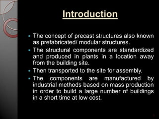
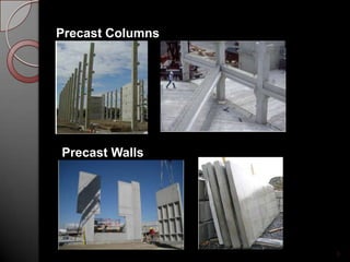
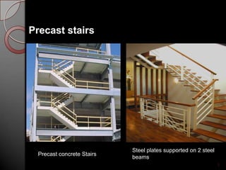
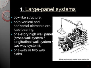
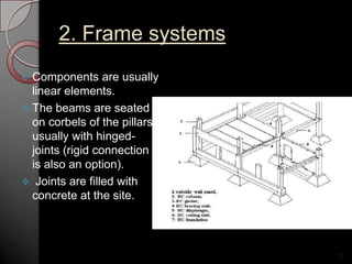
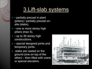
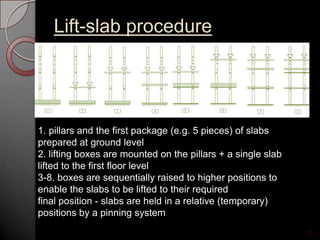
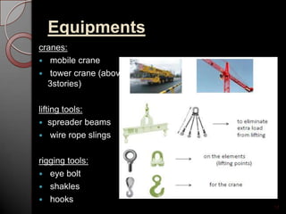
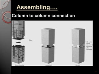
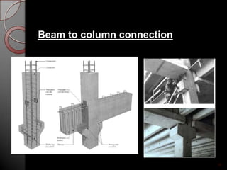
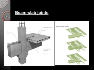
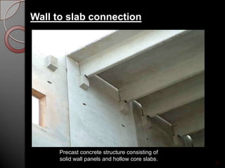
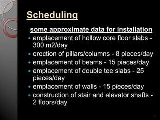
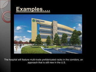
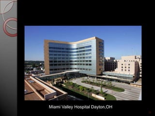
This document provides an overview of prefabricated modular structures. It discusses the introduction and features of prefabricated structures, comparing them to site-cast structures. It outlines the design concept, components, types of precast systems including large panel, frame, and lift-slab systems. It also discusses design considerations, equipment used, assembly process, scheduling, advantages including reduced costs and time, limitations, and concludes with examples of prefabricated hospital structures.


