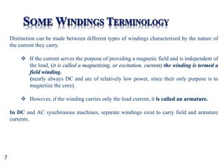
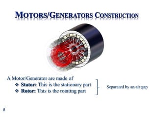
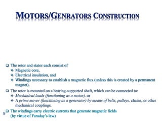
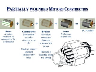
This document provides information about direct current (DC) motors, including:
- The three main types of DC motors: shunt wound, series wound, and separately excited and their characteristics.
- The principles of operation, construction, and torque-speed characteristics of DC motors.
- How to calculate torque, speed, induced emf, and other parameters for DC motors.
- Applications of the different DC motor types.
- Circuit diagrams and equations for analyzing DC motor performance.


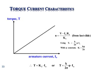
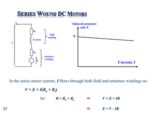
![34
K
R
I
V
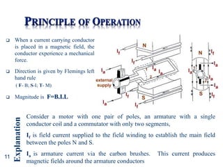
n
1
a
a
n]
K
-
[V
R
K
T 1
a
2
We had:
a
a
R
n
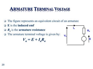
K
V
I 1
The torque-speed curve shows that shunt motors can be used to drive fairly constant
speed from no load to full torque
Therefore, ideal for use with machine tools, pumps, compressors etc.](https://image.slidesharecdn.com/unit7-dcmotors-230315084421-abc07faa/85/Unit7-DC_Motors-ppt-34-320.jpg)
![35
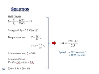
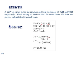
A 220V dc shunt motor has an armature resistance of 0.8 and field winding
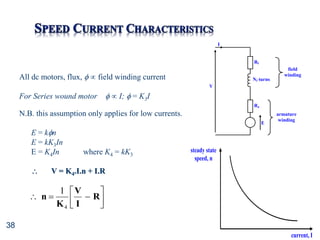
resistance of 220. The motor field characteristic [k versus field current] is
shown in Figure
a) Calculate the field current
If the motor drives a constant load torque of 17.5Nm, calculate
b) armature current
c) speed
Field current
(A)
0.5 1.5
0.0 1.0
2
4
6
k (Vs/rev)](https://image.slidesharecdn.com/unit7-dcmotors-230315084421-abc07faa/85/Unit7-DC_Motors-ppt-35-320.jpg)