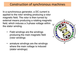
1. A synchronous generator produces power by inducing a 3-phase voltage in its stator windings via a rotating magnetic field created by its rotor.
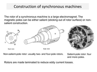
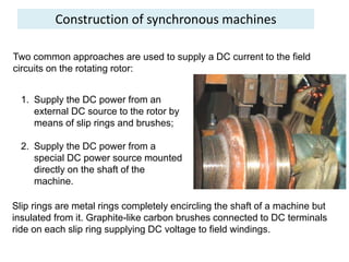
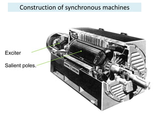
2. The rotor contains field windings that are supplied with DC current to produce the magnetic field.
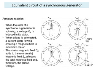
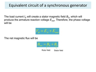
3. When load is applied, armature reaction causes the induced voltage to differ from the output voltage based on the load power factor.