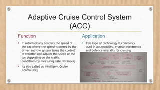
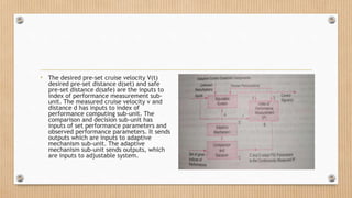
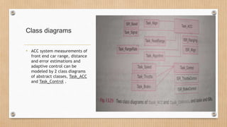
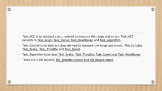
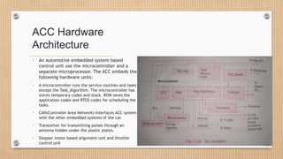
Case Study of an Embedded
System for an Adaptive Cruise
Control (ACC) in a Car
• Embedded
Systems in
Automobiles
• What is ACC
System, its
functions and
requirements?
• Working, ACC
Algorithm and
Hardware
Architecture
Embedded Systems in
Automobiles
• Automobiles have many
Embedded Systems called
ECU’s.
• A car may have the following
types of ECU’s embedded in
it.
• Engine control, Speed control
and braking systems, Safety
systems, Infotainment
systems etc.
Types of
ECU’S
Adaptive Cruise Control System
(ACC)
Function
• It automatically controls the speed of
the car where the speed is preset by the
driver and the system takes the control
of throttle and adjusts the speed of the
car depending on the traffic
conditions(by measuring safe distances).
• Its also called as Intelligent Cruise
Control(ICC)
Application
• This type of technology is commonly
used in automobiles, aviation electronics
and defence aircrafts for cruising
Requirements
Inputs and Outputs
Control Panel, Signals and
Notifications
Design Metrics, Test and
validation conditions
Inputs and
Outputs
• Inputs:
1. Present alignment of Radar (or laser)
beam emitter.
2. Delay interval in reflected pulse with
respect to transmitted pulse from
emitter.
3. Throttle position.
4. Speed from speedometer.
5. Brake status for brake activities from
brake pedal.
• Outputs:
• Transmitted pulse at regular intervals
• Alarms
• Range and speed messages
• Brake control
• Output to pedal system for applying
emergency brakes and driver for taking
charge of cruising from ACC system
Control Panel, Signals
and event notifications
• Control Panel:
• Switch cum display for ‘ON’, ‘OFF’,
‘RESUME’, ‘COAST’ and
‘SET/ACCELERATE’.
• The driver activates or deactivates, the
ACC system by pressing ‘ON’/‘OFF’
respectively.
• S/he sets the cruise speed by
‘SET/ACCELERATE’ switch. The driver
hands over or resumes the ACC by
pressing ‘COAST’ or ‘RESUME’
respectively.
• A switch glows green or red as per the
status when ACC activates.
• Signals and event notifications:
• User commands given as signals from
switches/ buttons. User control inputs
for ACC on, off, coast, resume,
set/accelerate buttons.
• Brake event (Brake taping to disable the
ACC system, as alternative to “cancel”
button at front panel.
• Safe/Unsafe distance notifications.
Design metrics, Test and
Validation conditions
• Design Metrics:
• Resolution: 2m inter car distance
• Performance: Safe distance setting 75m
to 200m.
• Process Deadline: Less than 1s response
on observation of un-safe distance of
front end car.
• User interface: Graphics at LCD or touch
screen display on LCD.
• Test and Validation Conditions:
• Test in dense as well as light traffic
conditions.
• Tested on plains, hills and valley roads.
• All user commands must function
correctly.
Working
• An ACC car system moves in a cruise
mode at a preset speed. A radar or laser
emits signals at regular intervals. These
signals are reflected from the vehicle in
front. When reflected signal received
earlier than expected from minimum
safe distance, it notifies the presence of
another vehicle to the system. The ACC
system then decelerates and the car
slows down. It accelerates again to the
preset speed when condition permit.
• New systems apply the brakes also and
deploy a Collision Mitigation Braking
(CMB) system. The CMB alerts the driver
if the object is at less than 100m
distance. If the driver still doesn’t
react, the system retracts, locks the
seatbelts and brakes hard.
Adaptive control
algorithm adapts and
functions
• An adaptive control means an
algorithm, the parameters in
which adapts to the present
status of the control inputs in
place of constant set of
mathematical parameters in
algorithmic equations.
• For an ACC system, an
adjustable system sub-unit
generates output control
signal to throttle valve.
• The desired pre-set cruise velocity V(t)
desired pre-set distance d(set) and safe
pre-set distance d(safe) are the inputs to
index of performance measurement sub-
unit. The measured cruise velocity v and
distance d has inputs to index of
performance computing sub-unit. The
comparison and decision sub-unit has
inputs of set performance parameters and
observed performance parameters. It sends
outputs which are inputs to adaptive
mechanism sub-unit. The adaptive
mechanism sub-unit sends outputs, which
are inputs to adjustable system.
Class diagrams
• ACC system measurements of
front end car range, distance
and error estimations and
adaptive control can be
modeled by 2 class diagrams
of abstract classes, Task_ACC
and Task_Control .
• Task_ACC is an abstract class, derived to measure the range and errors. Task_ACC
extends to Task_Align, Task_Signal, Task_ReadRange and Task_Algorithm.
• Task_Control is an abstract class derived to measure the range and errors. This includes
Task_Brake, Task_Throttle and Task_Speed.
• Task_Algorithm interfaces Task_Brake, Task_Throttle, Task_Speed and Task_ReadRange.
• There are 2 ISR objects, ISR_ThrottleControl and ISR_BrakeControl.
ACC Hardware
Architecture
• An automotive embedded system based
control unit use the microcontroller and a
separate microprocessor. The ACC embeds the
following hardware units:
• A microcontroller runs the service routines and tasks
except the Task_Algorithm. The microcontroller has
stores temporary codes and stack. ROM saves the
application codes and RTOS codes for scheduling the
tasks.
• CAN(Controller Area Network) interfaces ACC system
with the other embedded systems of the car.
• Transceiver for transmitting pulses through an
antenna hidden under the plastic plates.
• Stepper motor based alignment unit and throttle
control unit

Case study of Adaptive Cruise Control

  • 1.
    Case Study ofan Embedded System for an Adaptive Cruise Control (ACC) in a Car
  • 2.
    • Embedded Systems in Automobiles •What is ACC System, its functions and requirements? • Working, ACC Algorithm and Hardware Architecture
  • 3.
    Embedded Systems in Automobiles •Automobiles have many Embedded Systems called ECU’s. • A car may have the following types of ECU’s embedded in it. • Engine control, Speed control and braking systems, Safety systems, Infotainment systems etc.
  • 4.
  • 5.
    Adaptive Cruise ControlSystem (ACC) Function • It automatically controls the speed of the car where the speed is preset by the driver and the system takes the control of throttle and adjusts the speed of the car depending on the traffic conditions(by measuring safe distances). • Its also called as Intelligent Cruise Control(ICC) Application • This type of technology is commonly used in automobiles, aviation electronics and defence aircrafts for cruising
  • 6.
    Requirements Inputs and Outputs ControlPanel, Signals and Notifications Design Metrics, Test and validation conditions
  • 7.
    Inputs and Outputs • Inputs: 1.Present alignment of Radar (or laser) beam emitter. 2. Delay interval in reflected pulse with respect to transmitted pulse from emitter. 3. Throttle position. 4. Speed from speedometer. 5. Brake status for brake activities from brake pedal. • Outputs: • Transmitted pulse at regular intervals • Alarms • Range and speed messages • Brake control • Output to pedal system for applying emergency brakes and driver for taking charge of cruising from ACC system
  • 8.
    Control Panel, Signals andevent notifications • Control Panel: • Switch cum display for ‘ON’, ‘OFF’, ‘RESUME’, ‘COAST’ and ‘SET/ACCELERATE’. • The driver activates or deactivates, the ACC system by pressing ‘ON’/‘OFF’ respectively. • S/he sets the cruise speed by ‘SET/ACCELERATE’ switch. The driver hands over or resumes the ACC by pressing ‘COAST’ or ‘RESUME’ respectively. • A switch glows green or red as per the status when ACC activates. • Signals and event notifications: • User commands given as signals from switches/ buttons. User control inputs for ACC on, off, coast, resume, set/accelerate buttons. • Brake event (Brake taping to disable the ACC system, as alternative to “cancel” button at front panel. • Safe/Unsafe distance notifications.
  • 9.
    Design metrics, Testand Validation conditions • Design Metrics: • Resolution: 2m inter car distance • Performance: Safe distance setting 75m to 200m. • Process Deadline: Less than 1s response on observation of un-safe distance of front end car. • User interface: Graphics at LCD or touch screen display on LCD. • Test and Validation Conditions: • Test in dense as well as light traffic conditions. • Tested on plains, hills and valley roads. • All user commands must function correctly.
  • 10.
    Working • An ACCcar system moves in a cruise mode at a preset speed. A radar or laser emits signals at regular intervals. These signals are reflected from the vehicle in front. When reflected signal received earlier than expected from minimum safe distance, it notifies the presence of another vehicle to the system. The ACC system then decelerates and the car slows down. It accelerates again to the preset speed when condition permit. • New systems apply the brakes also and deploy a Collision Mitigation Braking (CMB) system. The CMB alerts the driver if the object is at less than 100m distance. If the driver still doesn’t react, the system retracts, locks the seatbelts and brakes hard.
  • 11.
    Adaptive control algorithm adaptsand functions • An adaptive control means an algorithm, the parameters in which adapts to the present status of the control inputs in place of constant set of mathematical parameters in algorithmic equations. • For an ACC system, an adjustable system sub-unit generates output control signal to throttle valve.
  • 12.
    • The desiredpre-set cruise velocity V(t) desired pre-set distance d(set) and safe pre-set distance d(safe) are the inputs to index of performance measurement sub- unit. The measured cruise velocity v and distance d has inputs to index of performance computing sub-unit. The comparison and decision sub-unit has inputs of set performance parameters and observed performance parameters. It sends outputs which are inputs to adaptive mechanism sub-unit. The adaptive mechanism sub-unit sends outputs, which are inputs to adjustable system.
  • 13.
    Class diagrams • ACCsystem measurements of front end car range, distance and error estimations and adaptive control can be modeled by 2 class diagrams of abstract classes, Task_ACC and Task_Control .
  • 14.
    • Task_ACC isan abstract class, derived to measure the range and errors. Task_ACC extends to Task_Align, Task_Signal, Task_ReadRange and Task_Algorithm. • Task_Control is an abstract class derived to measure the range and errors. This includes Task_Brake, Task_Throttle and Task_Speed. • Task_Algorithm interfaces Task_Brake, Task_Throttle, Task_Speed and Task_ReadRange. • There are 2 ISR objects, ISR_ThrottleControl and ISR_BrakeControl.
  • 15.
    ACC Hardware Architecture • Anautomotive embedded system based control unit use the microcontroller and a separate microprocessor. The ACC embeds the following hardware units: • A microcontroller runs the service routines and tasks except the Task_Algorithm. The microcontroller has stores temporary codes and stack. ROM saves the application codes and RTOS codes for scheduling the tasks. • CAN(Controller Area Network) interfaces ACC system with the other embedded systems of the car. • Transceiver for transmitting pulses through an antenna hidden under the plastic plates. • Stepper motor based alignment unit and throttle control unit