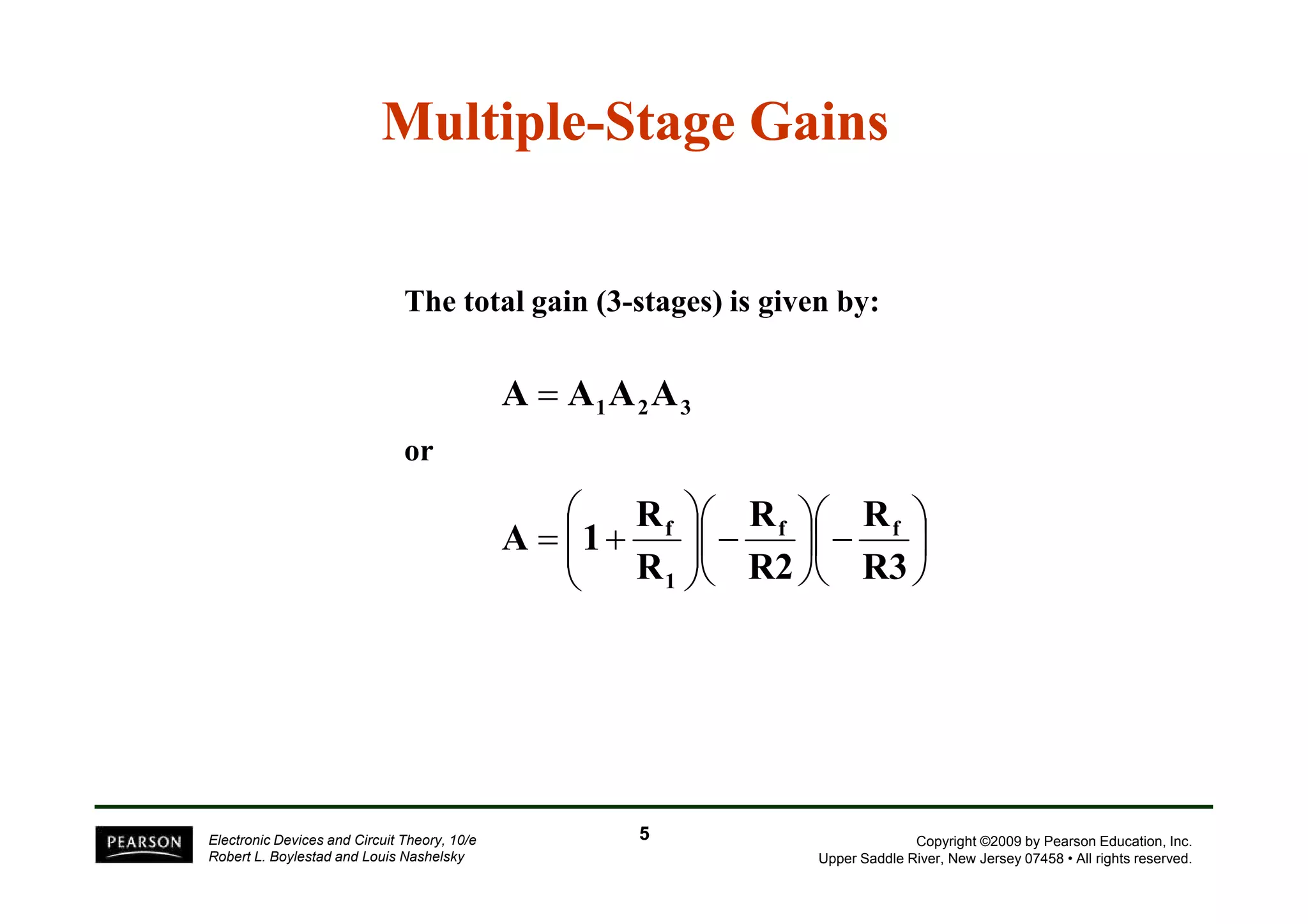
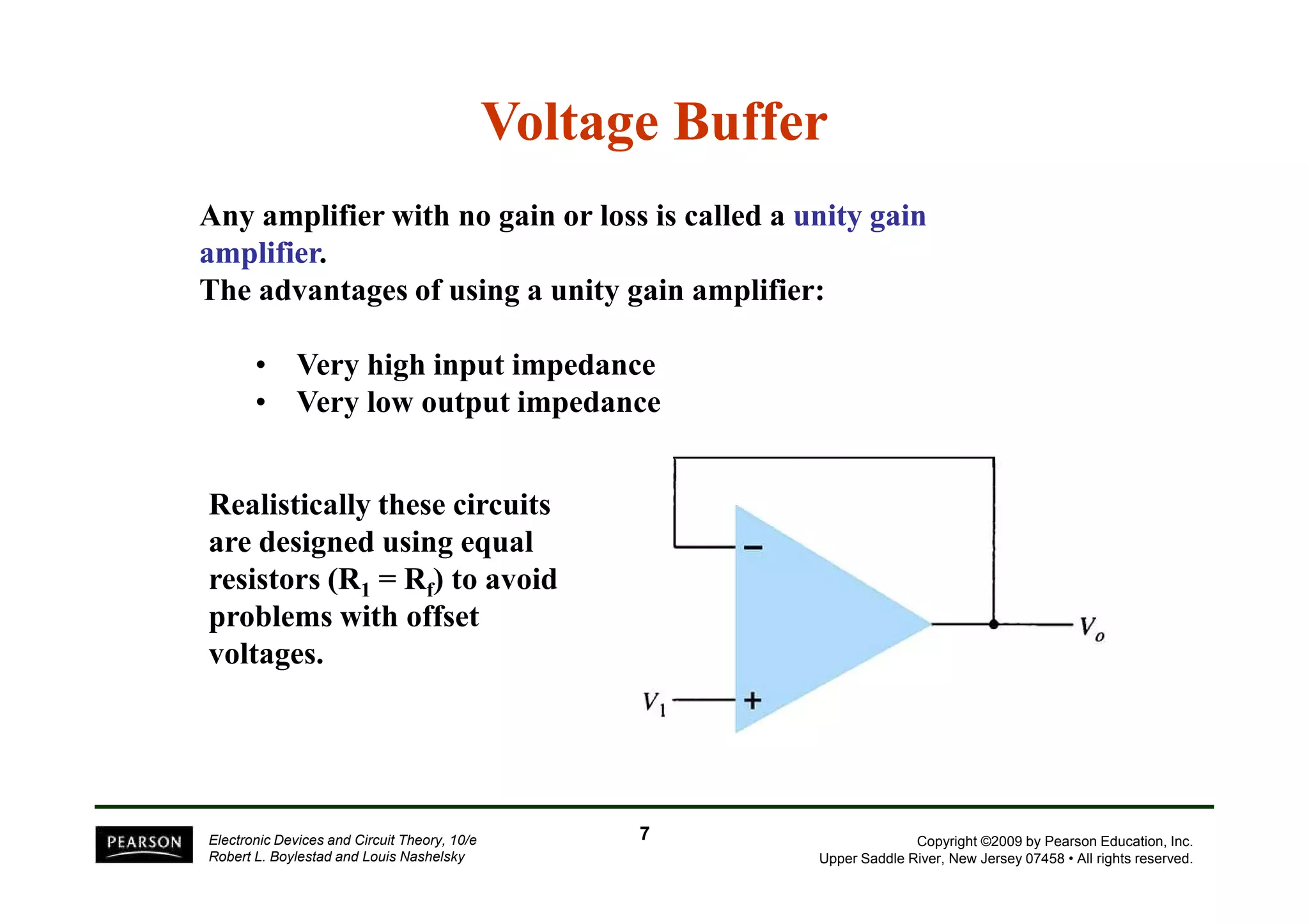
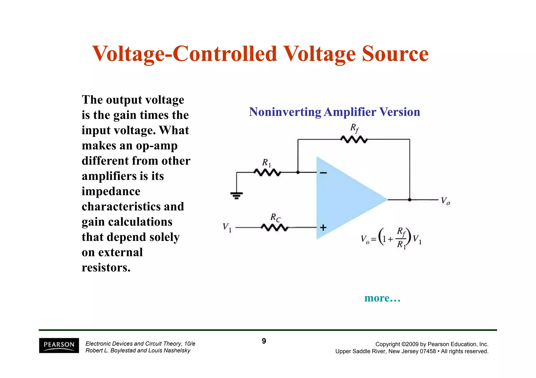
Download as PDF, PPTX
![Voltage Summing
The output is the sum
of individual signals
times the gain:
R
= − f
+ f
V
+ f
V
R
V
R
V
Copyright ©2009 by Pearson Education, Inc.
Upper Saddle River, New Jersey 07458 • All rights reserved.
Electronic Devices and Circuit Theory, 10/e
Robert L. Boylestad and Louis Nashelsky
[Formula 14.3]
3
3
2
2
1
1
o R
R
R
6](https://image.slidesharecdn.com/electronic-devices-and-circuit-theory-10th-ed-boylestad-chapter-11-141002064043-phpapp01/75/Electronic-devices-and-circuit-theory-10th-ed-boylestad-chapter-11-6-2048.jpg)
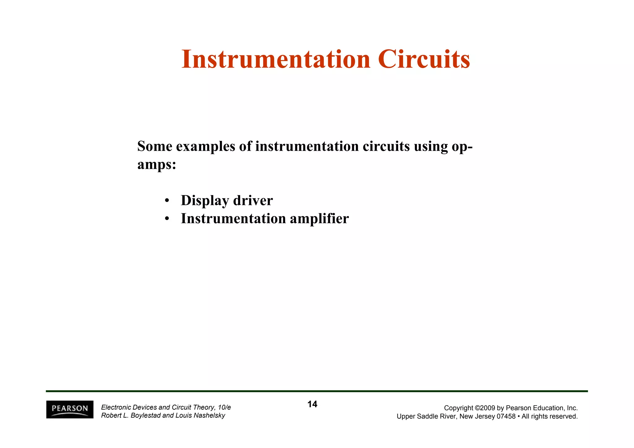
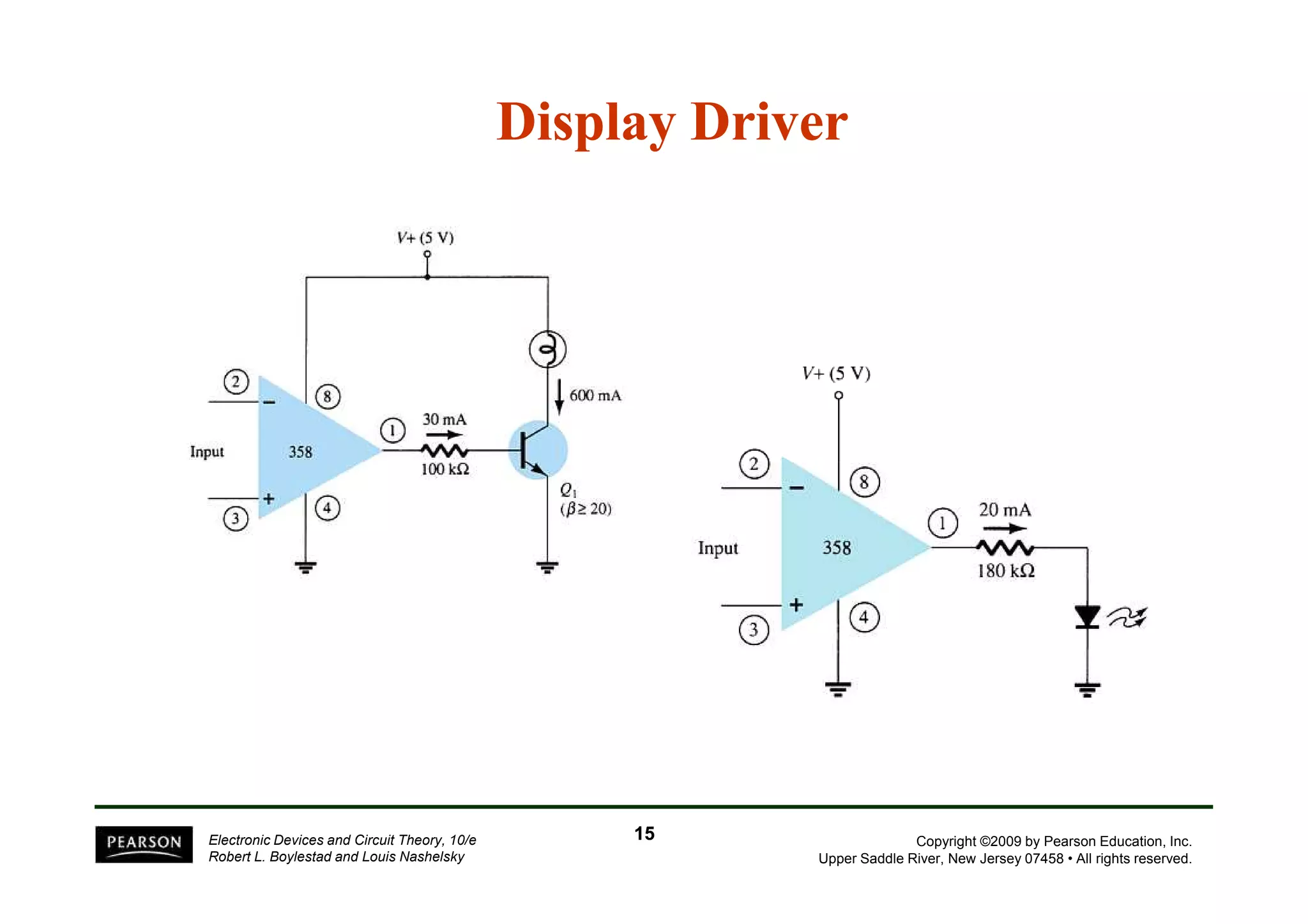
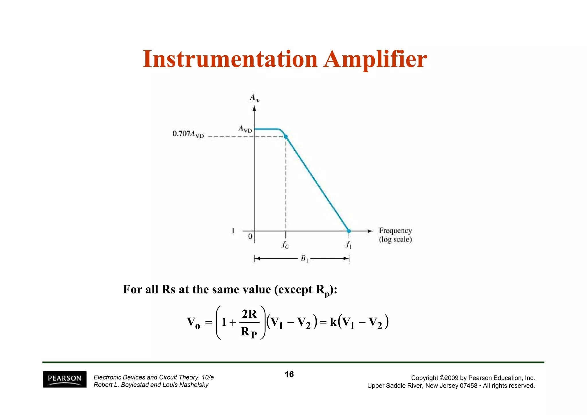

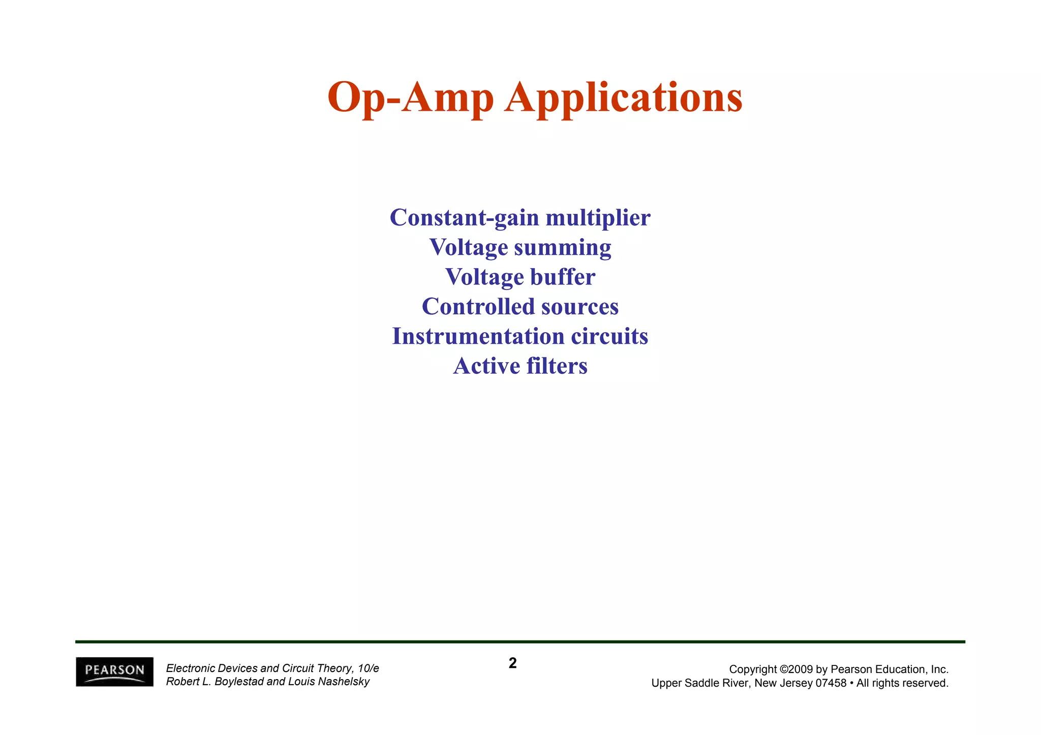
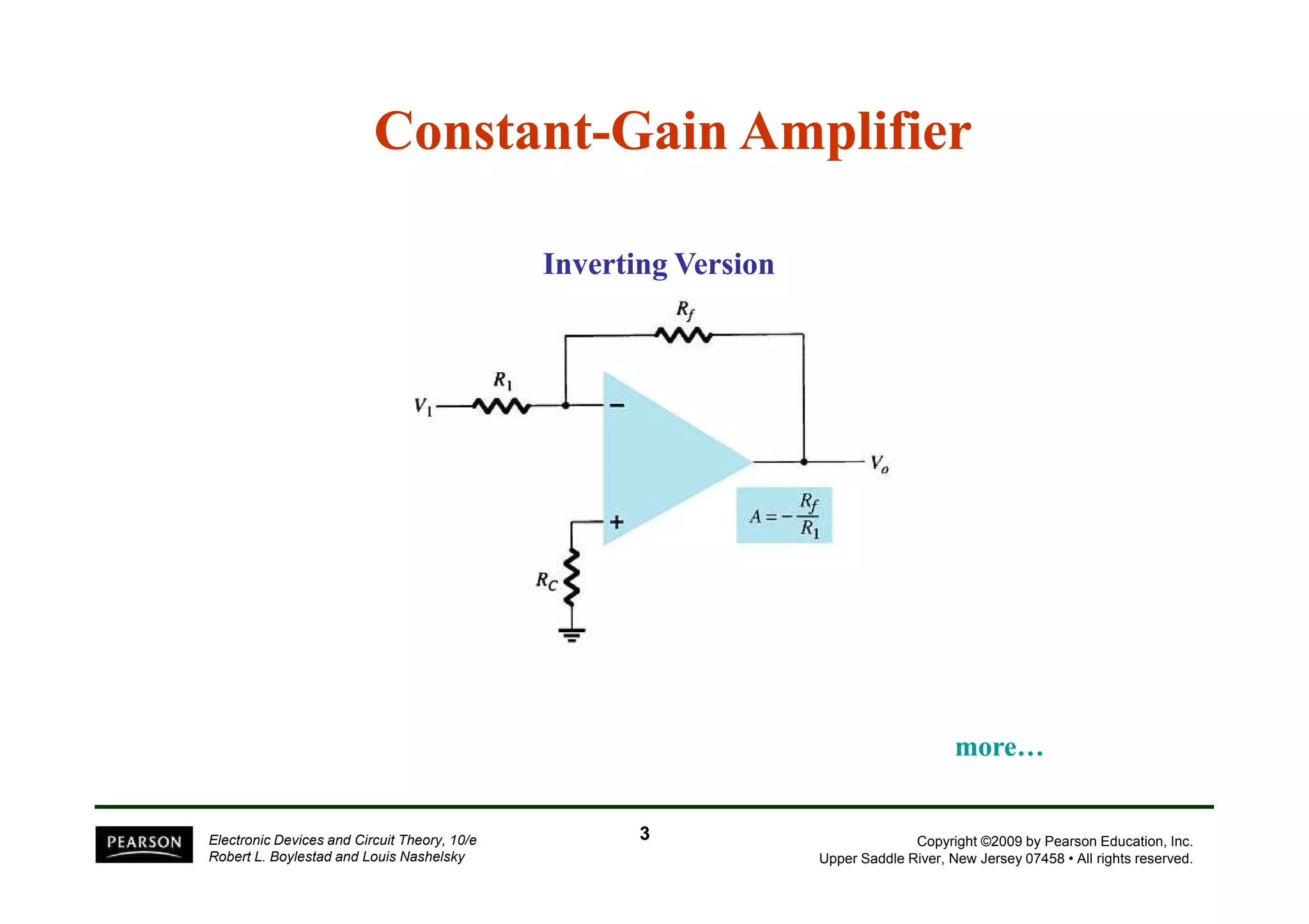
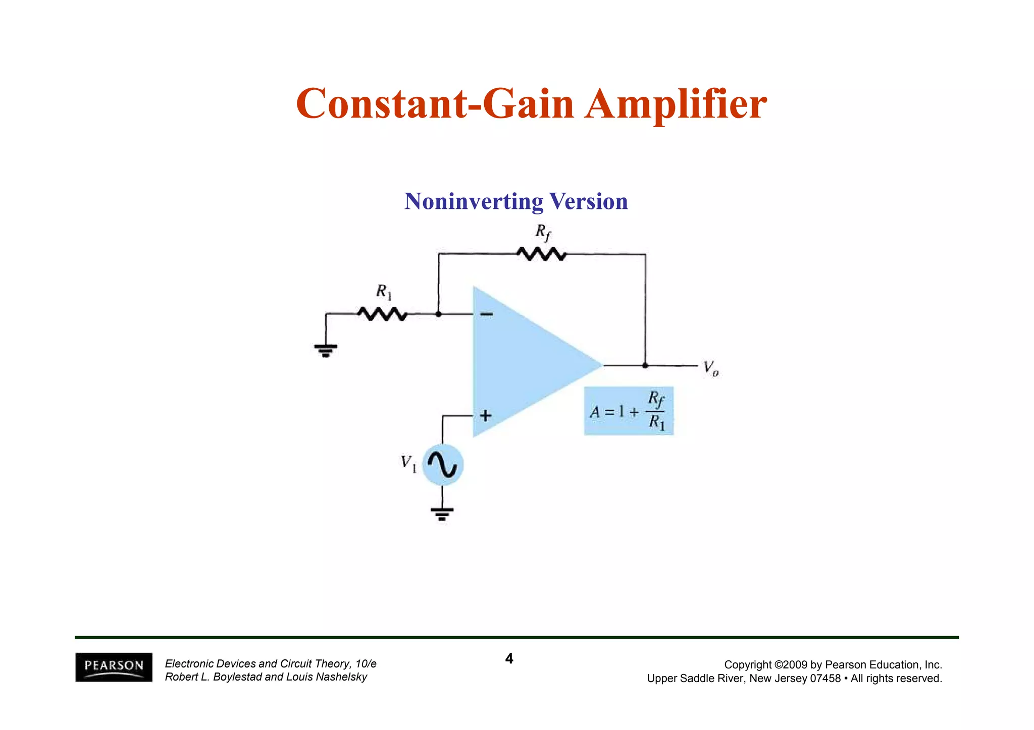
This document discusses various op-amp applications including constant-gain amplifiers, voltage summing, voltage buffers, controlled sources, instrumentation circuits, and active filters. It provides circuit diagrams and equations for calculating gain, cutoff frequencies, and other parameters. Applications include non-inverting and inverting amplifiers, voltage followers, voltage-controlled voltage sources, and first-order high-pass, low-pass, and bandpass filters.


