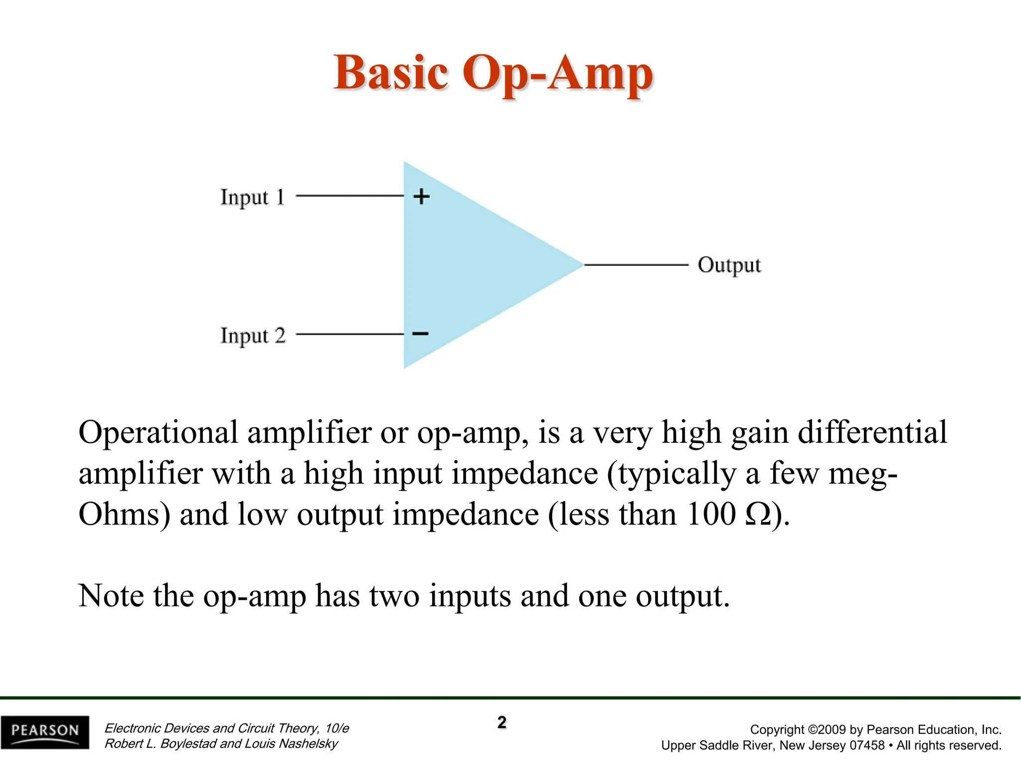
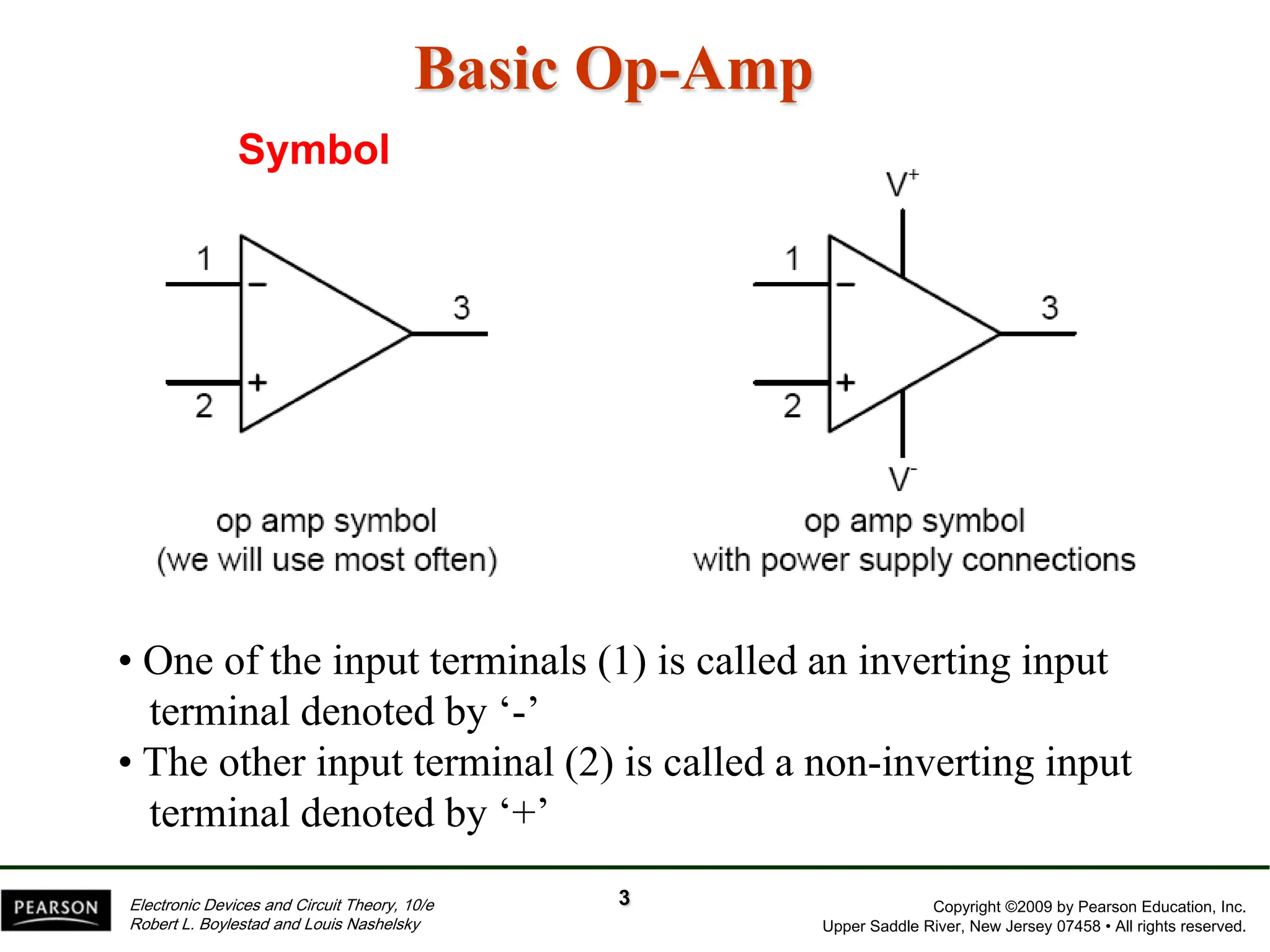
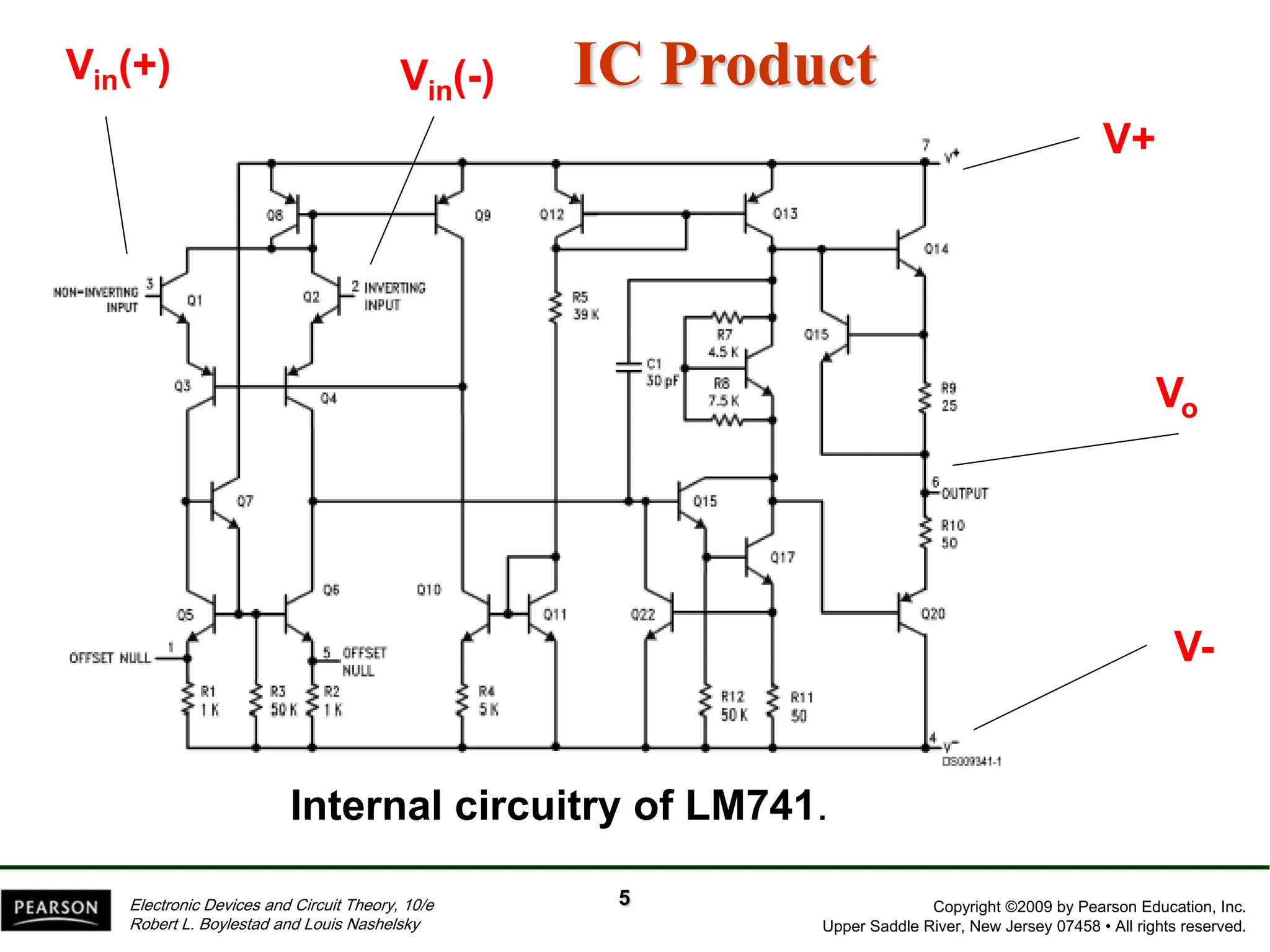
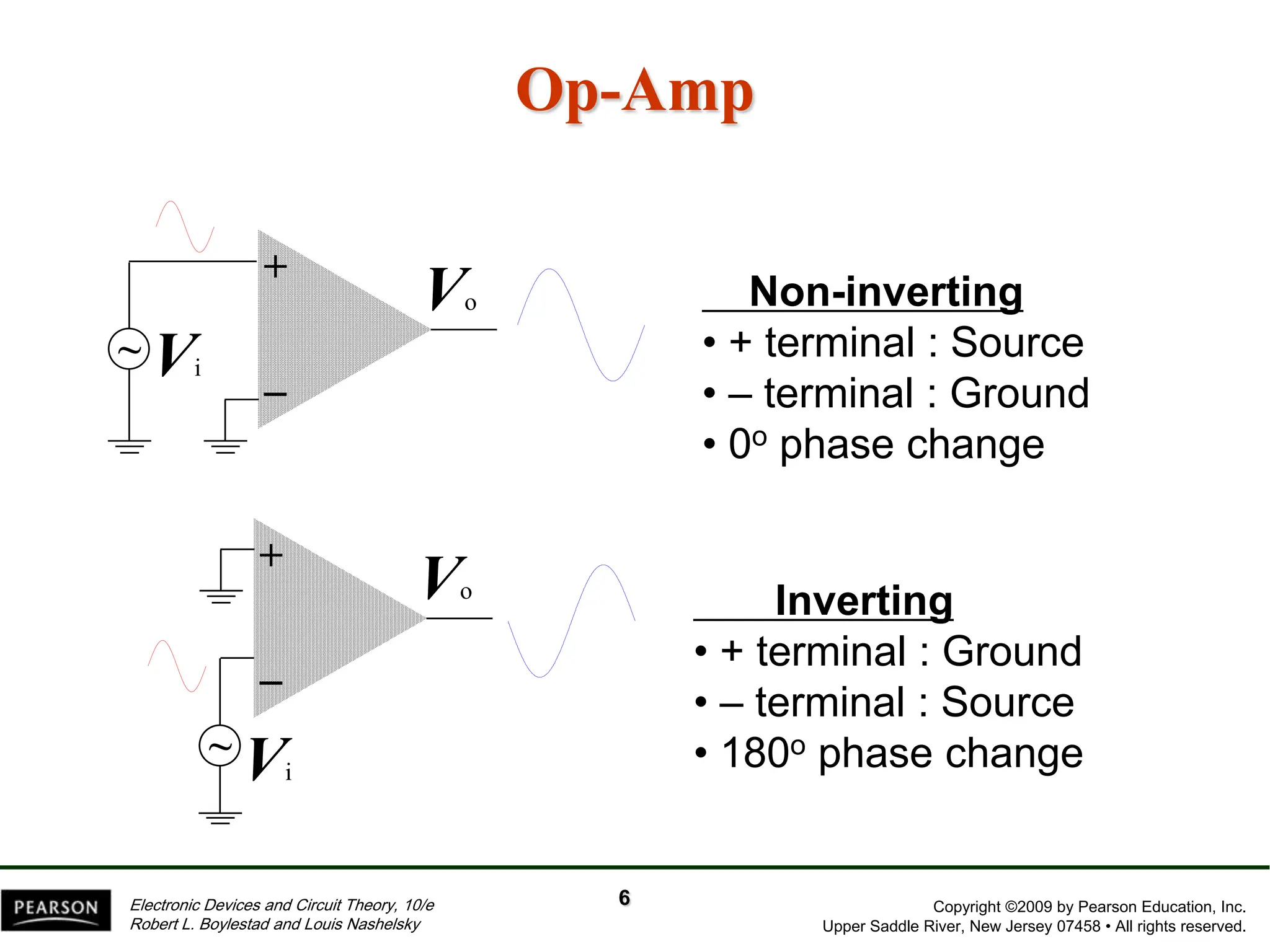
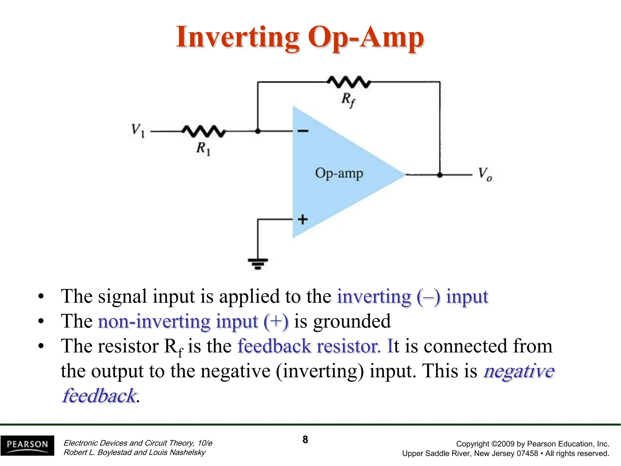
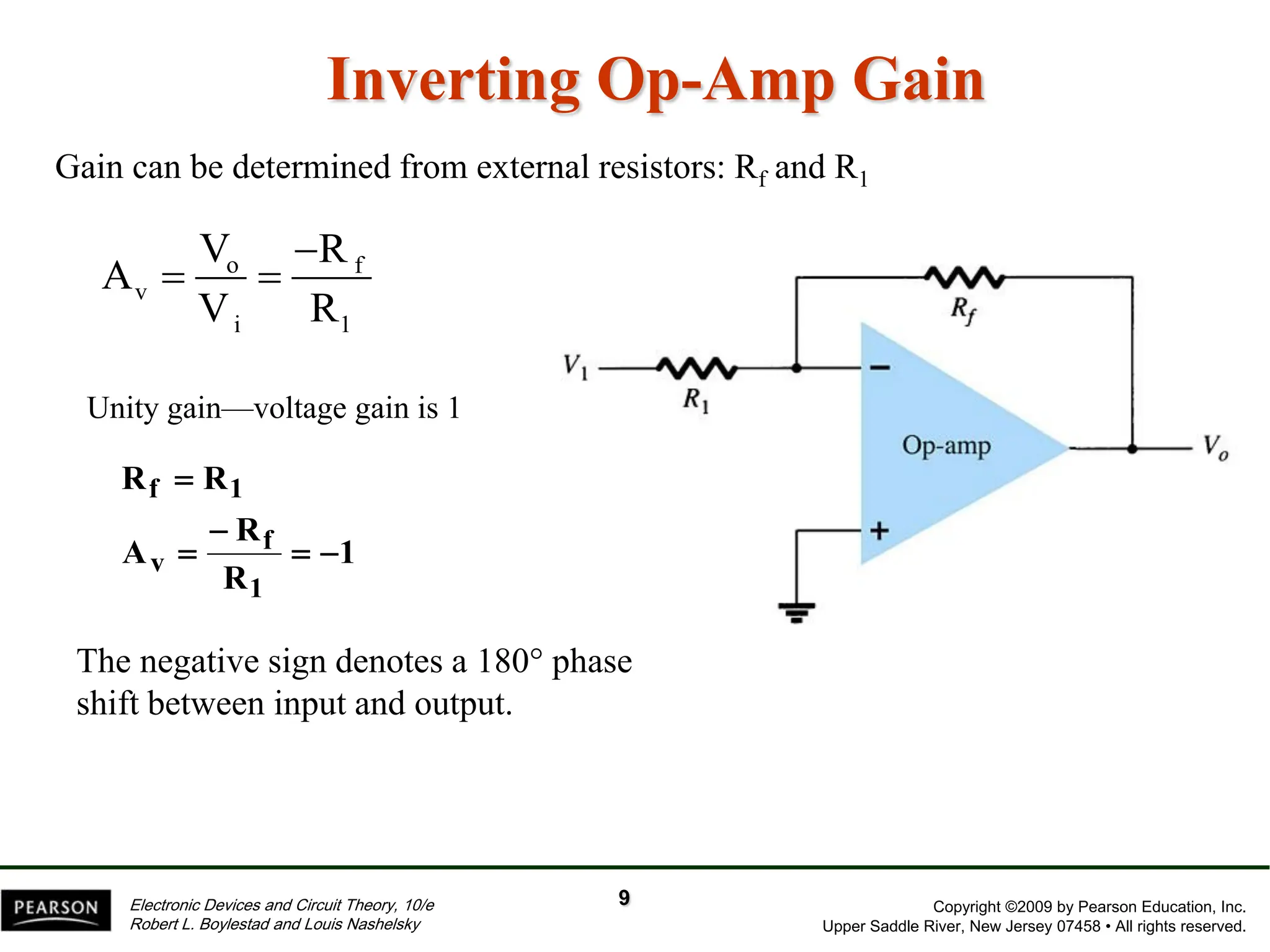
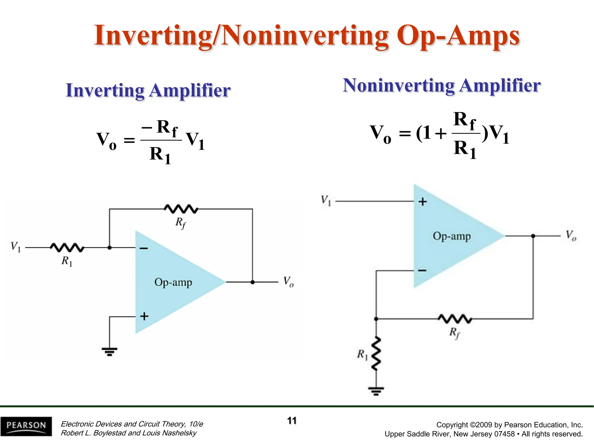
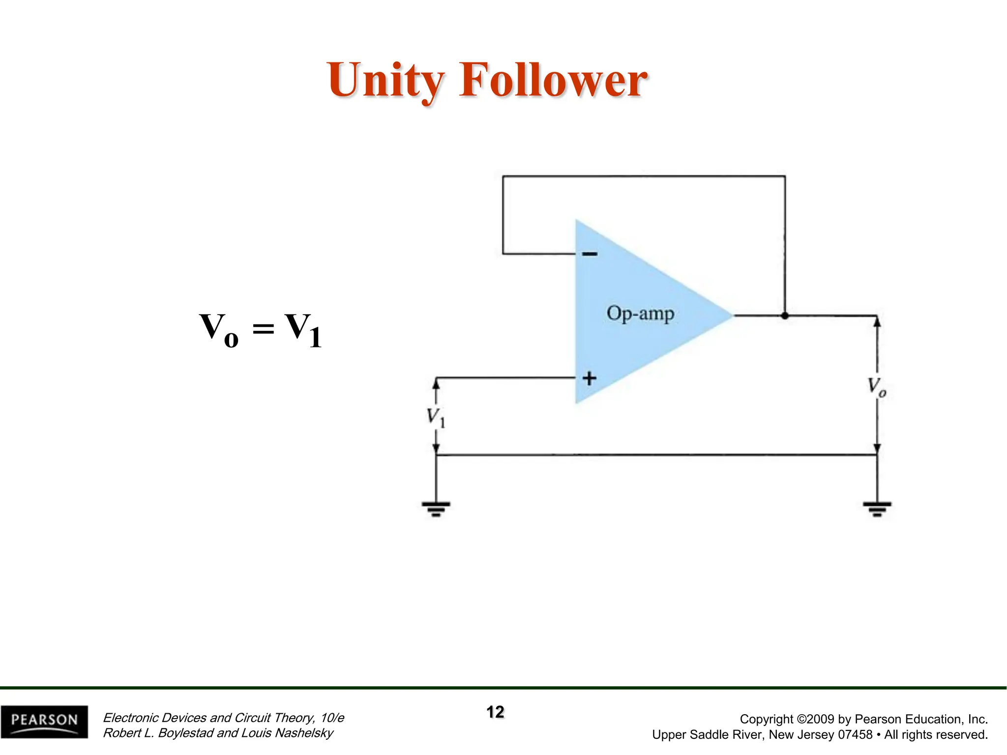
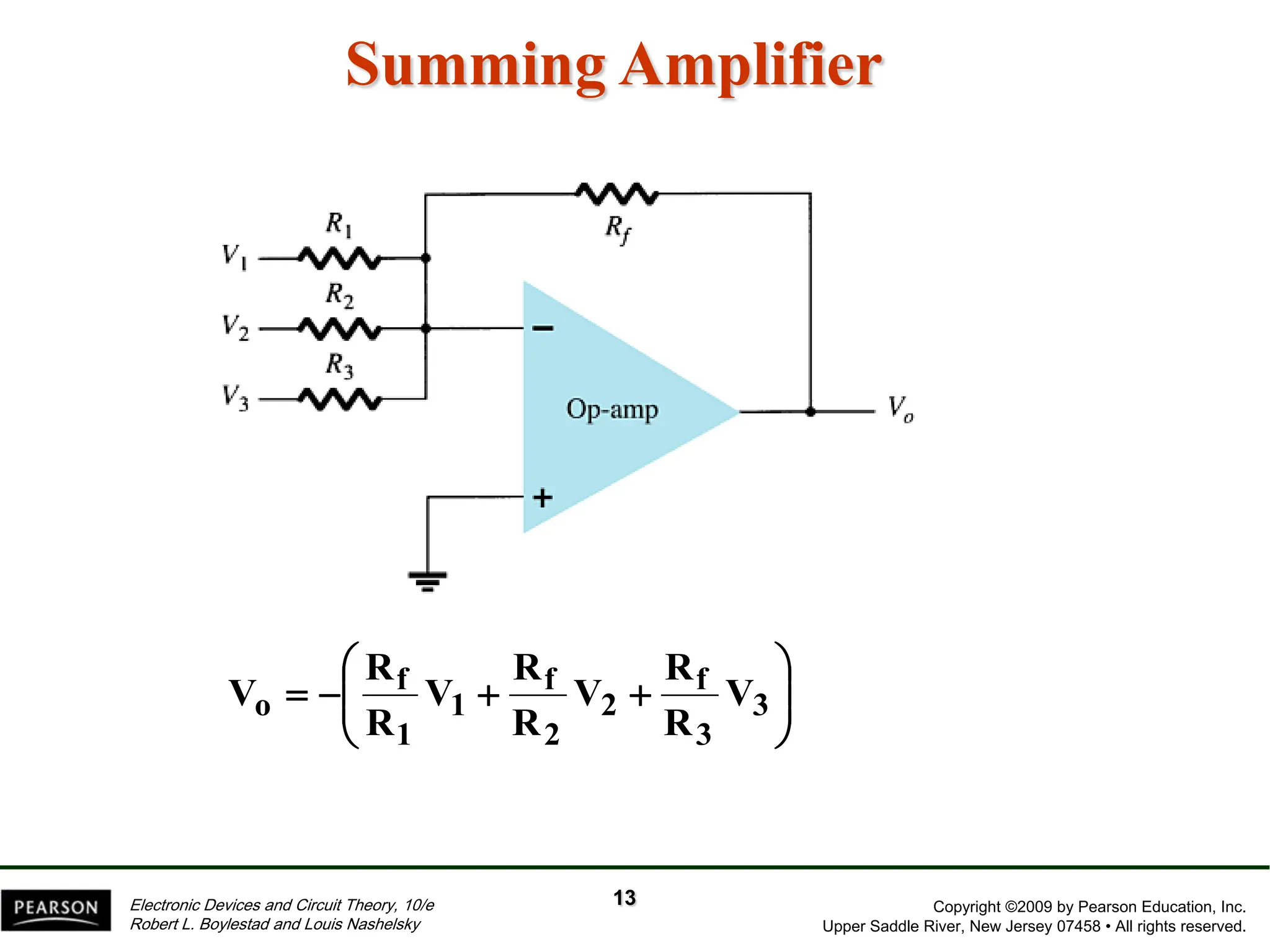
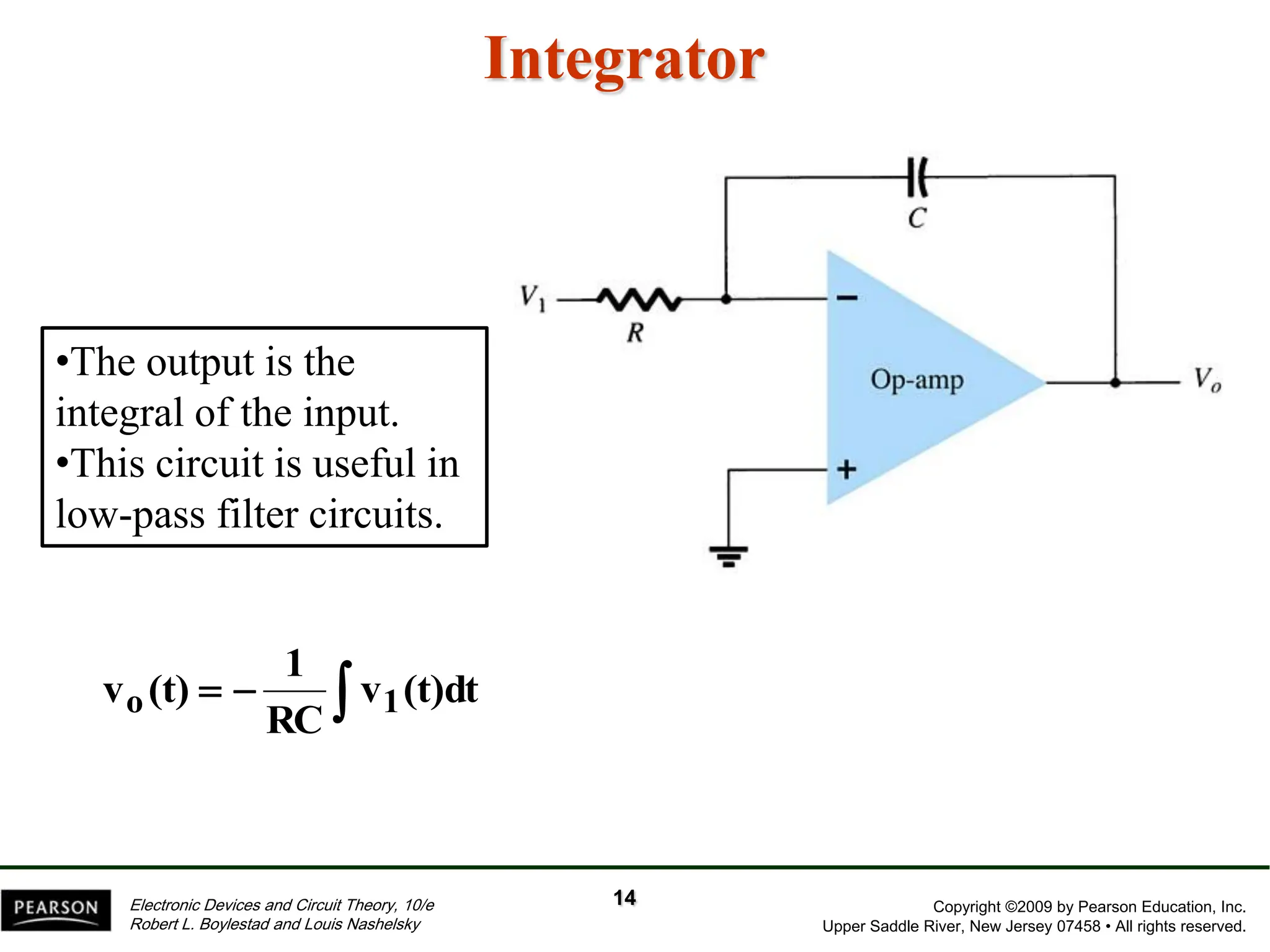
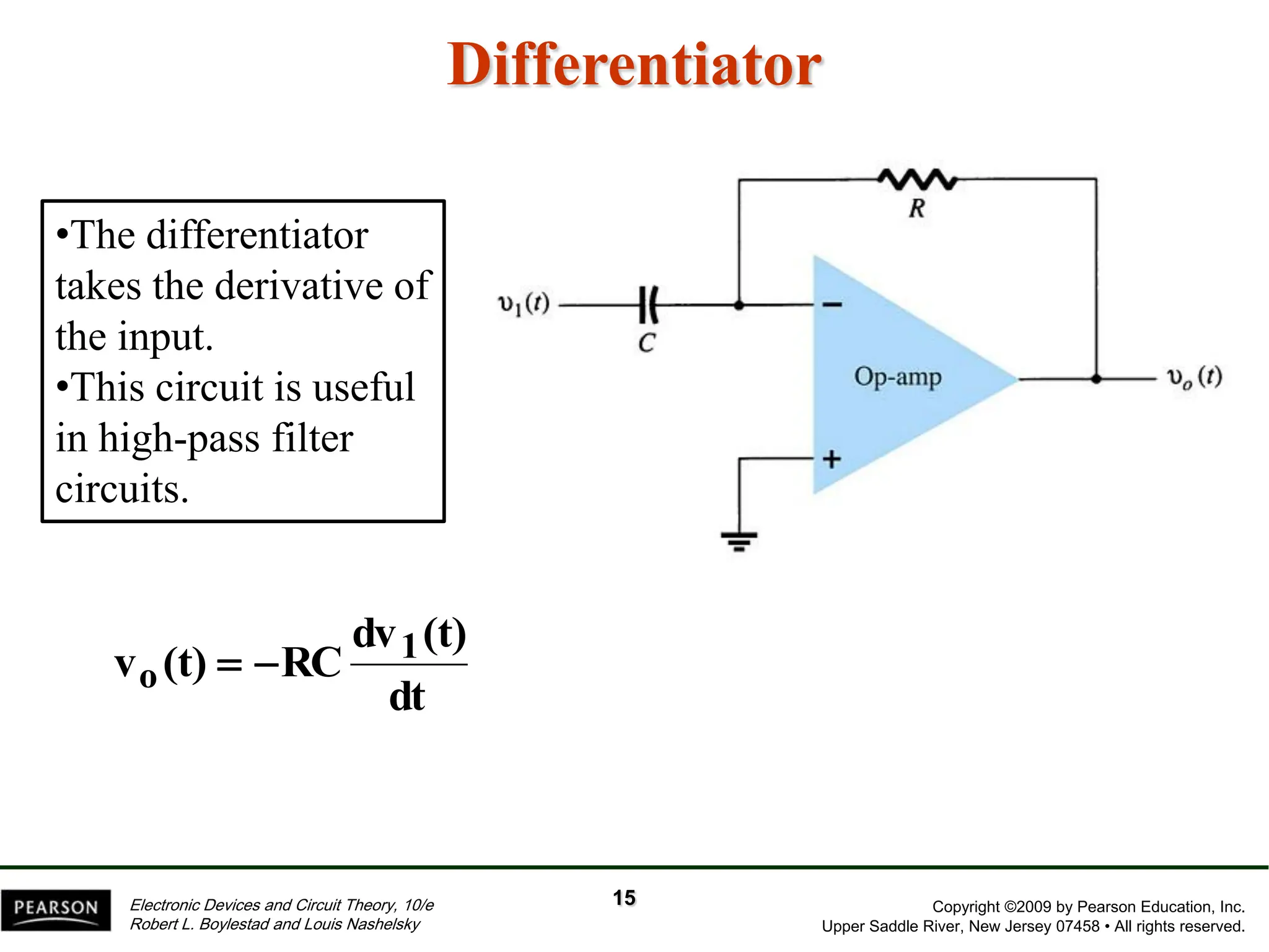
Chapter 10:
Operational Amplifiers
Copyright ©2009 by Pearson Education, Inc.
Upper Saddle River, New Jersey 07458 • All rights reserved.
Electronic Devices and Circuit Theory, 10/e
Robert L. Boylestad and Louis Nashelsky
Basic Op-Amp
Operational amplifier or op-amp, is a very high gain differential
amplifier with a high input impedance (typically a few meg-
Ohms) and low output impedance (less than 100 W).
Note the op-amp has two inputs and one output.
2
Copyright ©2009 by Pearson Education, Inc.
Upper Saddle River, New Jersey 07458 • All rights reserved.
Electronic Devices and Circuit Theory, 10/e
Robert L. Boylestad and Louis Nashelsky
Basic Op-Amp
3
Symbol
• One of the input terminals (1) is called an inverting input
terminal denoted by ‘-’
• The other input terminal (2) is called a non-inverting input
terminal denoted by ‘+’
Copyright ©2009 by Pearson Education, Inc.
Upper Saddle River, New Jersey 07458 • All rights reserved.
Electronic Devices and Circuit Theory, 10/e
Robert L. Boylestad and Louis Nashelsky
IC Product
4
+

1
2
3
4
8
7
6
5
OUTPUT A
-IN A
+IN A
V
V+
OUTPUT B
-IN B
+IN B
+

Dual op-amp 1458 device
Copyright ©2009 by Pearson Education, Inc.
Upper Saddle River, New Jersey 07458 • All rights reserved.
Electronic Devices and Circuit Theory, 10/e
Robert L. Boylestad and Louis Nashelsky
IC Product
5
V+
V-
Vo
Vin(-)
Internal circuitry of LM741.
Vin(+)
Copyright ©2009 by Pearson Education, Inc.
Upper Saddle River, New Jersey 07458 • All rights reserved.
Electronic Devices and Circuit Theory, 10/e
Robert L. Boylestad and Louis Nashelsky
Op-Amp
6
+

Vo
~ Vi
+

Vo
~
Vi
Non-inverting
• + terminal : Source
• – terminal : Ground
• 0o phase change
Inverting
• + terminal : Ground
• – terminal : Source
• 180o phase change
Copyright ©2009 by Pearson Education, Inc.
Upper Saddle River, New Jersey 07458 • All rights reserved.
Electronic Devices and Circuit Theory, 10/e
Robert L. Boylestad and Louis Nashelsky
Op-Amp Gain
Op-Amps have a very high gain. They can be connected open-
loop or closed-loop.
• Open-loop refers to a configuration where there is no
feedback from output back to the input. In the open-loop
configuration the gain can exceed 10,000.
• Closed-loop configuration reduces the gain. In order to
control the gain of an op-amp it must have feedback. This
feedback is a negative feedback. A negative feedback
reduces the gain and improves many characteristics of the
op-amp.
7
Copyright ©2009 by Pearson Education, Inc.
Upper Saddle River, New Jersey 07458 • All rights reserved.
Electronic Devices and Circuit Theory, 10/e
Robert L. Boylestad and Louis Nashelsky
Inverting Op-Amp
• The signal input is applied to the inverting (–) input
• The non-inverting input (+) is grounded
• The resistor Rf is the feedback resistor. It is connected from
the output to the negative (inverting) input. This is negative
feedback.
8
Copyright ©2009 by Pearson Education, Inc.
Upper Saddle River, New Jersey 07458 • All rights reserved.
Electronic Devices and Circuit Theory, 10/e
Robert L. Boylestad and Louis Nashelsky
Inverting Op-Amp Gain
Gain can be determined from external resistors: Rf and R1
Unity gain—voltage gain is 1
The negative sign denotes a 180 phase
shift between input and output.
o f
v
i 1
V R
A
V R

 
1
R
R
A
R
R
1
f
v
1
f





9
Copyright ©2009 by Pearson Education, Inc.
Upper Saddle River, New Jersey 07458 • All rights reserved.
Electronic Devices and Circuit Theory, 10/e
Robert L. Boylestad and Louis Nashelsky
Practical Op-Amp Circuits
Inverting amplifier
Noninverting amplifier
Unity follower
Summing amplifier
Integrator
Differentiator
10
Copyright ©2009 by Pearson Education, Inc.
Upper Saddle River, New Jersey 07458 • All rights reserved.
Electronic Devices and Circuit Theory, 10/e
Robert L. Boylestad and Louis Nashelsky
Inverting/Noninverting Op-Amps
1
1
f
o V
R
R
V


Inverting Amplifier Noninverting Amplifier
1
1
f
o V
)
R
R
1
(
V 

11
Copyright ©2009 by Pearson Education, Inc.
Upper Saddle River, New Jersey 07458 • All rights reserved.
Electronic Devices and Circuit Theory, 10/e
Robert L. Boylestad and Louis Nashelsky
Unity Follower
1
o V
V 
12
Copyright ©2009 by Pearson Education, Inc.
Upper Saddle River, New Jersey 07458 • All rights reserved.
Electronic Devices and Circuit Theory, 10/e
Robert L. Boylestad and Louis Nashelsky
Summing Amplifier











 3
3
f
2
2
f
1
1
f
o V
R
R
V
R
R
V
R
R
V
13
Copyright ©2009 by Pearson Education, Inc.
Upper Saddle River, New Jersey 07458 • All rights reserved.
Electronic Devices and Circuit Theory, 10/e
Robert L. Boylestad and Louis Nashelsky
Integrator
•The output is the
integral of the input.
•This circuit is useful in
low-pass filter circuits.


 (t)dt
v
RC
1
(t)
v 1
o
14
Copyright ©2009 by Pearson Education, Inc.
Upper Saddle River, New Jersey 07458 • All rights reserved.
Electronic Devices and Circuit Theory, 10/e
Robert L. Boylestad and Louis Nashelsky
Differentiator
•The differentiator
takes the derivative of
the input.
•This circuit is useful
in high-pass filter
circuits.
dt
(t)
dv
RC
(t)
v 1
o 

15

Chapter10_Electronic Devices and Circuit Theory.pdf

  • 1.
  • 2.
    Copyright ©2009 byPearson Education, Inc. Upper Saddle River, New Jersey 07458 • All rights reserved. Electronic Devices and Circuit Theory, 10/e Robert L. Boylestad and Louis Nashelsky Basic Op-Amp Operational amplifier or op-amp, is a very high gain differential amplifier with a high input impedance (typically a few meg- Ohms) and low output impedance (less than 100 W). Note the op-amp has two inputs and one output. 2
  • 3.
    Copyright ©2009 byPearson Education, Inc. Upper Saddle River, New Jersey 07458 • All rights reserved. Electronic Devices and Circuit Theory, 10/e Robert L. Boylestad and Louis Nashelsky Basic Op-Amp 3 Symbol • One of the input terminals (1) is called an inverting input terminal denoted by ‘-’ • The other input terminal (2) is called a non-inverting input terminal denoted by ‘+’
  • 4.
    Copyright ©2009 byPearson Education, Inc. Upper Saddle River, New Jersey 07458 • All rights reserved. Electronic Devices and Circuit Theory, 10/e Robert L. Boylestad and Louis Nashelsky IC Product 4 +  1 2 3 4 8 7 6 5 OUTPUT A -IN A +IN A V V+ OUTPUT B -IN B +IN B +  Dual op-amp 1458 device
  • 5.
    Copyright ©2009 byPearson Education, Inc. Upper Saddle River, New Jersey 07458 • All rights reserved. Electronic Devices and Circuit Theory, 10/e Robert L. Boylestad and Louis Nashelsky IC Product 5 V+ V- Vo Vin(-) Internal circuitry of LM741. Vin(+)
  • 6.
    Copyright ©2009 byPearson Education, Inc. Upper Saddle River, New Jersey 07458 • All rights reserved. Electronic Devices and Circuit Theory, 10/e Robert L. Boylestad and Louis Nashelsky Op-Amp 6 +  Vo ~ Vi +  Vo ~ Vi Non-inverting • + terminal : Source • – terminal : Ground • 0o phase change Inverting • + terminal : Ground • – terminal : Source • 180o phase change
  • 7.
    Copyright ©2009 byPearson Education, Inc. Upper Saddle River, New Jersey 07458 • All rights reserved. Electronic Devices and Circuit Theory, 10/e Robert L. Boylestad and Louis Nashelsky Op-Amp Gain Op-Amps have a very high gain. They can be connected open- loop or closed-loop. • Open-loop refers to a configuration where there is no feedback from output back to the input. In the open-loop configuration the gain can exceed 10,000. • Closed-loop configuration reduces the gain. In order to control the gain of an op-amp it must have feedback. This feedback is a negative feedback. A negative feedback reduces the gain and improves many characteristics of the op-amp. 7
  • 8.
    Copyright ©2009 byPearson Education, Inc. Upper Saddle River, New Jersey 07458 • All rights reserved. Electronic Devices and Circuit Theory, 10/e Robert L. Boylestad and Louis Nashelsky Inverting Op-Amp • The signal input is applied to the inverting (–) input • The non-inverting input (+) is grounded • The resistor Rf is the feedback resistor. It is connected from the output to the negative (inverting) input. This is negative feedback. 8
  • 9.
    Copyright ©2009 byPearson Education, Inc. Upper Saddle River, New Jersey 07458 • All rights reserved. Electronic Devices and Circuit Theory, 10/e Robert L. Boylestad and Louis Nashelsky Inverting Op-Amp Gain Gain can be determined from external resistors: Rf and R1 Unity gain—voltage gain is 1 The negative sign denotes a 180 phase shift between input and output. o f v i 1 V R A V R    1 R R A R R 1 f v 1 f      9
  • 10.
    Copyright ©2009 byPearson Education, Inc. Upper Saddle River, New Jersey 07458 • All rights reserved. Electronic Devices and Circuit Theory, 10/e Robert L. Boylestad and Louis Nashelsky Practical Op-Amp Circuits Inverting amplifier Noninverting amplifier Unity follower Summing amplifier Integrator Differentiator 10
  • 11.
    Copyright ©2009 byPearson Education, Inc. Upper Saddle River, New Jersey 07458 • All rights reserved. Electronic Devices and Circuit Theory, 10/e Robert L. Boylestad and Louis Nashelsky Inverting/Noninverting Op-Amps 1 1 f o V R R V   Inverting Amplifier Noninverting Amplifier 1 1 f o V ) R R 1 ( V   11
  • 12.
    Copyright ©2009 byPearson Education, Inc. Upper Saddle River, New Jersey 07458 • All rights reserved. Electronic Devices and Circuit Theory, 10/e Robert L. Boylestad and Louis Nashelsky Unity Follower 1 o V V  12
  • 13.
    Copyright ©2009 byPearson Education, Inc. Upper Saddle River, New Jersey 07458 • All rights reserved. Electronic Devices and Circuit Theory, 10/e Robert L. Boylestad and Louis Nashelsky Summing Amplifier             3 3 f 2 2 f 1 1 f o V R R V R R V R R V 13
  • 14.
    Copyright ©2009 byPearson Education, Inc. Upper Saddle River, New Jersey 07458 • All rights reserved. Electronic Devices and Circuit Theory, 10/e Robert L. Boylestad and Louis Nashelsky Integrator •The output is the integral of the input. •This circuit is useful in low-pass filter circuits.    (t)dt v RC 1 (t) v 1 o 14
  • 15.
    Copyright ©2009 byPearson Education, Inc. Upper Saddle River, New Jersey 07458 • All rights reserved. Electronic Devices and Circuit Theory, 10/e Robert L. Boylestad and Louis Nashelsky Differentiator •The differentiator takes the derivative of the input. •This circuit is useful in high-pass filter circuits. dt (t) dv RC (t) v 1 o   15