Downloaded 983 times

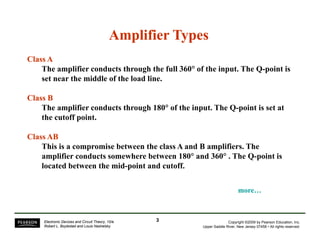
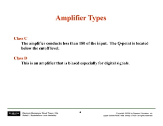


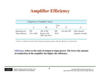
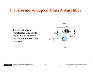
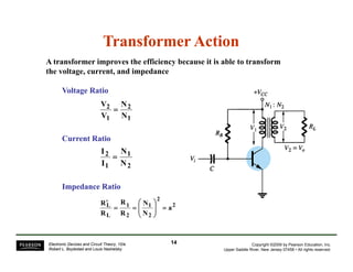
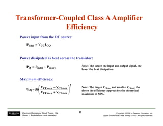
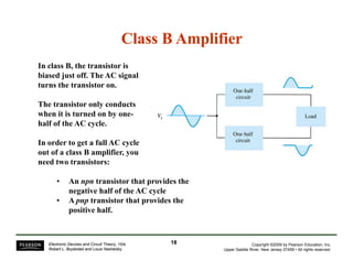

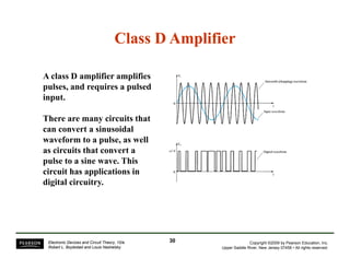

This document discusses different classes of power amplifiers. Class A amplifiers conduct over the full 360 degrees of the input cycle but have low efficiency around 25%. Class B amplifiers conduct over 180 degrees and have higher efficiency of 78.5% but require two transistors for a full output cycle. Class AB is a compromise between the two. Class C conducts less than 180 degrees and uses a tuned circuit for output. Class D is for digital signals and requires pulse conversion circuits. Transformer coupling can improve class A efficiency to 50% by spreading out voltage and current swings.