Download as PDF, PPTX

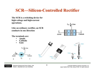
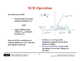
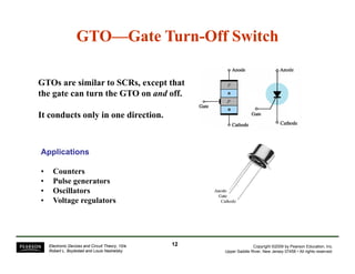
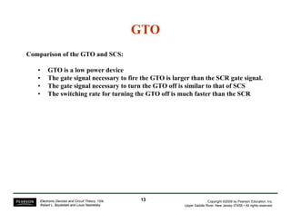
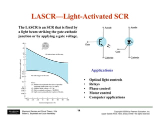
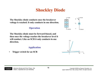
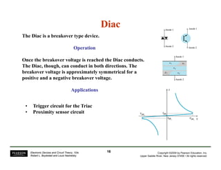
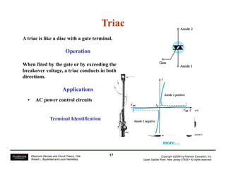
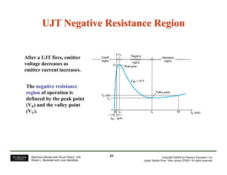
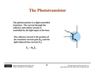
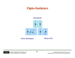
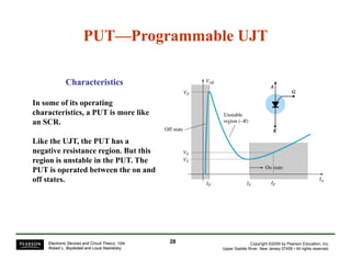

The document discusses several types of semiconductor devices used for switching and control applications, including silicon-controlled rectifiers (SCRs), silicon-controlled switches (SCSs), gate turn-off switches (GTOs), light-activated SCRs (LASCRs), diacs, triacs, unijunction transistors (UJTs), programmable UJTs (PUTs), phototransistors, and opto-isolators. Key points about SCRs are that they conduct in one direction and can be turned on by applying a gate voltage while forward biased or off by removing the anode-cathode voltage. SCSs and GTOs are similar but can be turned on and off through


