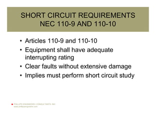
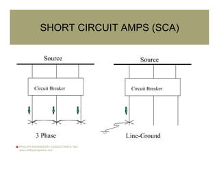
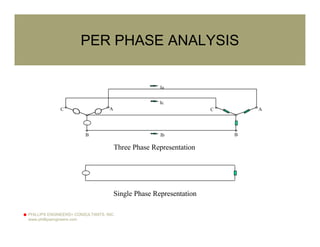
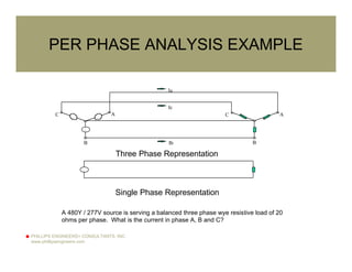
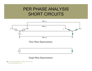
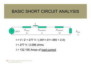
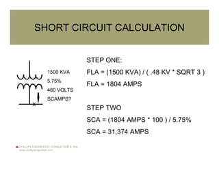
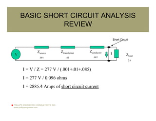
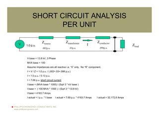
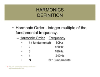
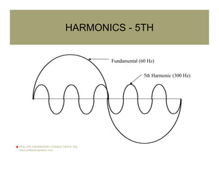
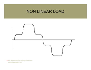
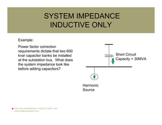
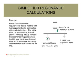
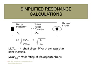
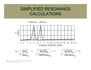
PHILLIPS ENGINEERS+ CONSULTANTS, INC.
www.phillipsengineers.com
ELECTRIC POWER CALCULATIONS
ROCKY MOUNTAIN
ELECTRICAL LEAGUE
OCTOBER 24, 2002
K. James Phillips, Jr., P.E.
jphillips@phillipsengineers.com
PHILLIPS ENGINEERS+ CONSULTANTS, INC.
www.phillipsengineers.com
ELECTRIC POWER CALCULATIONS
• OVERVIEW
• PER PHASE
• SHORT CIRCUIT
• PER UNIT
• HARMONICS
PHILLIPS ENGINEERS+ CONSULTANTS, INC.
www.phillipsengineers.com
WHY ELECTRIC POWER CALCULATIONS
• USED TO PREDICT
OUTCOMES
• SHORT CIRCUITS
• HARMONICS
• VOLTAGES
• LOADS
PHILLIPS ENGINEERS+ CONSULTANTS, INC.
www.phillipsengineers.com
THE BASICS
• ALL ELECTRICAL THEORY RELATES
BACK TO THE BASICS
• Volts, Amps, Ohms
II
Z
V
V = I * Z
Z = V / I
I = V / Z
PHILLIPS ENGINEERS+ CONSULTANTS, INC.
www.phillipsengineers.com
SERIES COMBINATIONS
Z1
Z2
Z
PHILLIPS ENGINEERS+ CONSULTANTS, INC.
www.phillipsengineers.com
COMPLEX IMPEDANCE
R
X
Z
0
X = Z * Sin 0
R = X
X/R
Z = R2+X2
PHILLIPS ENGINEERS+ CONSULTANTS, INC.
www.phillipsengineers.com
SHORT CIRCUIT REQUIREMENTS
NEC 110-9 AND 110-10
• Articles 110-9 and 110-10
• Equipment shall have adequate
interrupting rating
• Clear faults without extensive damage
• Implies must perform short circuit study
PHILLIPS ENGINEERS+ CONSULTANTS, INC.
www.phillipsengineers.com
AIC RATINGS
CIRCUIT BREAKER SHORT CIRCUIT
TYPE RATING
QOB 10,000
QOB-H 22,000
QOB-VH 42,000
PHILLIPS ENGINEERS+ CONSULTANTS, INC.
www.phillipsengineers.com
SHORT CIRCUIT AMPS (SCA)
Source
Circuit Breaker
Source
3 Phase
Circuit Breaker
Line-Ground
PHILLIPS ENGINEERS+ CONSULTANTS, INC.
www.phillipsengineers.com
PER PHASE ANALYSIS
~
~
~
~
A
B
C A
B
C
Ia
Ib
Ic
~
Three Phase Representation
Single Phase Representation
PHILLIPS ENGINEERS+ CONSULTANTS, INC.
www.phillipsengineers.com
PER PHASE ANALYSIS EXAMPLE
~
~
~
~
A
B
C A
B
C
Ia
Ib
Ic
~
Three Phase Representation
Single Phase Representation
A 480Y / 277V source is serving a balanced three phase wye resistive load of 20
ohms per phase. What is the current in phase A, B and C?
PHILLIPS ENGINEERS+ CONSULTANTS, INC.
www.phillipsengineers.com
PER PHASE ANALYSIS
SHORT CIRCUITS
~
~
~
~
A
B
C A
B
C
Ia
Ib
Ic
~
Three Phase Representation
Single Phase Representation
PHILLIPS ENGINEERS+ CONSULTANTS, INC.
www.phillipsengineers.com
DATA
SOURCE IMPEDANCE
• THEVENIN
EQUIVALANT
IMPEDANCE
PHILLIPS ENGINEERS+ CONSULTANTS, INC.
www.phillipsengineers.com
DATA
TRANSFORMER IMPEDANCE
• TRANSFORMER
IMPEDANCE
PHILLIPS ENGINEERS+ CONSULTANTS, INC.
www.phillipsengineers.com
DATA
CONDUCTOR IMPEDANCE
• CONDUCTOR
IMPEDANCE
PHILLIPS ENGINEERS+ CONSULTANTS, INC.
www.phillipsengineers.com
BASIC SHORT CIRCUIT ANALYSIS
I = V / Z = 277 V / (.001+.01+.085 + 2.0)
I = 277 V / 2.096 ohms
I = 132.156 Amps of load current
I
V
Zsource
.001
Ztransformer
.01
Zconductor
.085
Zload
2.0
277 V
PHILLIPS ENGINEERS+ CONSULTANTS, INC.
www.phillipsengineers.com
BASIC SHORT CIRCUIT ANALYSIS
I = V / Z = 277 V / (.001+.01+.085)
I = 277 V / 0.096 ohms
I = 2885.4 Amps of short circuit current
IZsource
.001
Ztransformer
.01
Zconductor
.085
Zload
2.0
Short Circuit
V
PHILLIPS ENGINEERS+ CONSULTANTS, INC.
www.phillipsengineers.com
SCA < AIC
CALCULATED
SHORT CIRCUIT
AMPS MUST BE
LESS THAN AIC
RATING
PHILLIPS ENGINEERS+ CONSULTANTS, INC.
www.phillipsengineers.com
CALCULATION TRICK
TRANSFORMER IMPEDANCE
• VOLTAGE
• %Z
• KVA
PHILLIPS ENGINEERS+ CONSULTANTS, INC.
www.phillipsengineers.com
CALCULATION TRICK
TRANSFORMER IMPEDANCE
Transformer
Variable voltage source
Short Circuit
A
Percent Impedance = Percent rated primary
voltage that causes rated base/ambient full
load current to flow in the secondary of a
short circuited transformer.
i.e.. 5.75 percent primary voltage causes
full load current in short circuited secondary,
the percent impedance is 5.75%
%Z = 100%
FLA SCA
SCA = (FLA * 100)
%Z
PHILLIPS ENGINEERS+ CONSULTANTS, INC.
www.phillipsengineers.com
SHORT CIRCUIT CALCULATION
EXAMPLE:
1500 KVA TRANSFORMER
5.75% IMPEDANCE
480 VOLT SECONDARY
1500 KVA
5.75%
480 VOLTS
SCAMPS?
X
PHILLIPS ENGINEERS+ CONSULTANTS, INC.
www.phillipsengineers.com
SHORT CIRCUIT CALCULATION
STEP ONE:
FLA = (1500 KVA) / ( .48 KV * SQRT 3 )
FLA = 1804 AMPS
STEP TWO
SCA = (1804 AMPS * 100 ) / 5.75%
SCA = 31,374 AMPS
1500 KVA
5.75%
480 VOLTS
SCAMPS?
X
PHILLIPS ENGINEERS+ CONSULTANTS, INC.
www.phillipsengineers.com
PROBLEM WITH IMPEDANCE ON TWO
SIDES OF TRANSFORMER
10 : 1 RATIO
X
20 OHMS
0.8 OHMS
Z1(VIEWED FROM SECONDARY)
= Z1 * (1 / 10)2 = 20 Ù * .01 = .002 Ù
Z2(VIEWED FROM SECONDARY)
= Z2 * (10 / 1)2 = 0.8 Ù * 100 = 80 Ù
PHILLIPS ENGINEERS+ CONSULTANTS, INC.
www.phillipsengineers.com
WHY PER UNIT?
• Calculations that involve impedances at
several voltage levels via transformers,
can become complicated due to the
transformer turns ratio.
• Per unit eliminates need to “reflect”
impedances to different voltages.
PHILLIPS ENGINEERS+ CONSULTANTS, INC.
www.phillipsengineers.com
PER UNIT EXAMPLE
Example:
A base number of 500 is used. The following is a
summary of per unit values for various numbers:
Number Per Unit Per Cent
250 0.5 p.u. 50%
500 1.0 p.u. 100%
1000 2.0 p.u 200%
PHILLIPS ENGINEERS+ CONSULTANTS, INC.
www.phillipsengineers.com
BASE QUANTITIES
Current (p.u.) = Actual Current
Base Current
Voltage (p.u.) = Actual Voltage
Base Voltage
Impedance (p.u.) = Actual Impedance
Base Impedance
Power (p.u.) = Actual Power
Base Power
PHILLIPS ENGINEERS+ CONSULTANTS, INC.
www.phillipsengineers.com
BASE QUANTITIES
• The per unit system requires two base
quantities to be selected:
– Base kVA - Fixed Quantity
– Base Voltage - Variable Based on Voltage
• Two base quantities are calculated:
– Base Impedance - function of base voltage
– Base Current - function of base voltage
PHILLIPS ENGINEERS+ CONSULTANTS, INC.
www.phillipsengineers.com
BASE KVA
(SELECTED)
BASE KVA (MVA):
In electric power systems, the base quantity that
remains constant throughout the system is the base
kVA. The kVA base is not affected by voltage levels
or transformer turns ratios. The amount of kVA
entering the primary of a transformer is the same as
the kVA leaving the secondary of the transformer
(neglecting transformer losses).
Any arbitrary number may be selected as the kVA
base, however, most electric utilities use a 100,000
kVA base commonly referred to as a 100 MVA base.
PHILLIPS ENGINEERS+ CONSULTANTS, INC.
www.phillipsengineers.com
BASE VOLTAGE
(SELECTED)
BASE VOLTAGE:
The base voltage will vary depending on the voltage
level of the system. The base voltage is generally
the nominal voltage of a particular voltage level.
PER UNIT VOLTAGE
V p.u. = V actual / V base V actual = V base * V p.u.
Example:
V base = 13.8 kV
V actual = 13.4 kV
V p.u. = 13.4 kV / 13.8 kV = 0.97 p.u.
PHILLIPS ENGINEERS+ CONSULTANTS, INC.
www.phillipsengineers.com
BASE CURRENT
(CALCULATED)
• I base = MVAbase * 1000 / (sqrt 3 * kVbase)
• I base = kVAbase / (sqrt 3 * kVbase)
PER UNIT CURRENT
I p.u. = I actual / I base I actual = I base * I p.u.
Example:
Bases: 100 MVA, 13.8 kV
I base = (100 MVA * 1000) / (sqrt 3 * 13.8 kV) = 4183 Amps
Actual Amps = 2500 Amps
I p.u. = I actual / I base = 2500 / 4183 = 0.598 p.u.
PHILLIPS ENGINEERS+ CONSULTANTS, INC.
www.phillipsengineers.com
BASE IMPEDANCE
(CALCULATED)
• Z base = kVbase
2 / MVA base
Per Unit Impedance:
Bases: 100 MVA, 13.8kV
Actual Impedance = 0.32 + j0.27 ohms
Z base = 13.8 kV2 / 100 MVA = 1.90 ohms
Z p.u. = 0.168 + j0.142 p.u.
PHILLIPS ENGINEERS+ CONSULTANTS, INC.
www.phillipsengineers.com
TABLE OF BASE VALUES
100 MVA - NOMINAL VOLTAGES
Voltage (kV) Impedance
(Ohms)
Current
(Amps)
765 5852.25 75.47
500 2500.00 115.47
345 1190.25 167.35
230 529.00 251.02
138 190.40 418.37
115 132.25 502.04
69 47.61 836.74
34.5 11.90 1673.48
23 5.29 2510.22
13.8 1.90 4183.70
PHILLIPS ENGINEERS+ CONSULTANTS, INC.
www.phillipsengineers.com
BASIC SHORT CIRCUIT ANALYSIS
REVIEW
I = V / Z = 277 V / (.001+.01+.085)
I = 277 V / 0.096 ohms
I = 2885.4 Amps of short circuit current
IZsource
.001
Ztransformer
.01
Zconductor
.085
Zload
2.0
Short Circuit
V
PHILLIPS ENGINEERS+ CONSULTANTS, INC.
www.phillipsengineers.com
SHORT CIRCUIT ANALYSIS
PER UNIT
Zload
V base = 13.8 kV, 3 Phase
MVA base = 100
Assume impedances are all reactive i.e. “X” only. No “R” component.
I = V / Z = 1.0 p.u. / (.002+.03+.098 p.u.)
I = 1.0 p.u. / 0.13 p.u.
I = 7.69 p.u. short circuit current
I base = (MVA base * 1000) / (Sqrt 3 * kV base )
I base = ( 100 MVA * 1000 ) / (Sqrt 3 * 13.8 kV)
I base = 4183.7 Amps
I actual = I p.u. * I base I actual = 7.69 p.u. * 4183.7 Amps I actual = 32,172.6 Amps
IV
Zsource
.002p.u.
Ztransformer
.03p.u.
Zconductor
.098p.u.
1.0 p.u.
PHILLIPS ENGINEERS+ CONSULTANTS, INC.
www.phillipsengineers.com
HARMONICS
DEFINITION
• Harmonic Order - integer multiple of the
fundamental frequency.
– Harmonic Order Frequency
• 1 ( fundamental) 60Hz
• 2 120Hz
• 3 180Hz
• 4 240Hz
• N N * Fundamental
PHILLIPS ENGINEERS+ CONSULTANTS, INC.
www.phillipsengineers.com
HARMONICS - 5TH
5th Harmonic (300 Hz)
Fundamental (60 Hz)
PHILLIPS ENGINEERS+ CONSULTANTS, INC.
www.phillipsengineers.com
NON LINEAR LOAD
PHILLIPS ENGINEERS+ CONSULTANTS, INC.
www.phillipsengineers.com
SOURCE OF HARMONICS
THE LOAD
• Solid State Motor
Drives
• Rectifiers
• UPS systems
• Computer power
supplies
• Fluorescent lighting
electronic ballast's
PHILLIPS ENGINEERS+ CONSULTANTS, INC.
www.phillipsengineers.com
FREQUENCY SPECTRUM
1 3 5 7 9 11
Harmonic Order
Magnitude
PHILLIPS ENGINEERS+ CONSULTANTS, INC.
www.phillipsengineers.com
HARMONIC RELATED PROBLEMS
• Blown Capacitors / Capacitors Fuses
• Transformer Overheating
• Neutral Overheating
• Motor / Generator Overheating
• Equipment Misoperation
• Circuit Breaker Misoperation
• Communication Interference
PHILLIPS ENGINEERS+ CONSULTANTS, INC.
www.phillipsengineers.com
EFFECTS OF CAPACITORS
• Without capacitors, the
circuit is predominantly
inductive.
• When capacitors are
added, an L-C circuit
results.
PHILLIPS ENGINEERS+ CONSULTANTS, INC.
www.phillipsengineers.com
SYSTEM IMPEDANCE
INDUCTIVE ONLY
Example:
Power factor correction
requirements dictate that two 600
kvar capacitor banks be installed
at the substation bus. What does
the system impedance look like
before adding capacitors?
Short Circuit
Capacity = 30MVA
Harmonic
Source
PHILLIPS ENGINEERS+ CONSULTANTS, INC.
www.phillipsengineers.com
SYSTEM IMPEDANCE
INDUCTIVE ONLY
Frequency (harmonic order)
Z
(Ohms
)
1 2 3 4 5 6 7 8 9 10 11 12 13 14 15 16 17
Z = jwl, w = 2pi*f, f = frequency
PHILLIPS ENGINEERS+ CONSULTANTS, INC.
www.phillipsengineers.com
SIMPLIFIED RESONANCE
CALCULATIONS
Example:
Power factor correction
requirements dictate that two 600
kvar capacitor banks be installed
at the substation bus. The utility
short circuit current is 30 MVA
(36,084 Amps @ 480V). What is
the resonance frequency when
the 600 kvar bank is on line and
what is the resonance frequency
when both 600 kvar banks are on
line.
Short Circuit
Capacity = 30MVA
2 x 600 kvar
Capacitor BankHarmonic Source
5TH, 7TH, 11TH, 13TH
PHILLIPS ENGINEERS+ CONSULTANTS, INC.
www.phillipsengineers.com
SIMPLIFIED RESONANCE
CALCULATIONS
MVAsc = short circuit MVA at the capacitor
bank location.
Mvarcap = Mvar rating of the capacitor bank
Source
Impedance
Power
Factor
Capacitor
Harmonic
Source
XL XC
hr = MVAsc = Xc
Mvarcap Xsc
PHILLIPS ENGINEERS+ CONSULTANTS, INC.
www.phillipsengineers.com
SIMPLIFIED RESONANCE
CALCULATIONS
Frequency (harmonic order)
Z
(Ohms
)
1 2 3 4 5 6 7 8 9 10 11 12 13 14 15 16 17
1200 kvar 600 kvar
hr = MVAsc =
Mvarcap
30 MVAsc = 7
0.600 Mvarcap
30 MVAsc = 5
1.200 Mvarcap
PHILLIPS ENGINEERS+ CONSULTANTS, INC.
www.phillipsengineers.com
RESULTS
• PRODUCES SEVERE DISTORTION
• DESIGN CAPACITOR AS HARMONIC
FILTER
PHILLIPS ENGINEERS+ CONSULTANTS, INC.
www.phillipsengineers.com
IEEE-519
• Sets limits for
voltage and current
distortion at PCC
• PCC is the point of
common coupling
PHILLIPS ENGINEERS+ CONSULTANTS, INC.
www.phillipsengineers.com
QUESTIONS ???
CONTACT INFORMATION:
PHILLIPS ENGINEERS + CONSULTANTS, INC.
4450 BELDEN VILLAGE ST., N.W. SUITE 309
CANTON, OHIO 44718
Tel: 330.491.0261
Fax: 330.491.0265
jphillips@phillipsengineers.com
DESIGN ENGINEERING
ANALYSIS
FEASABILITY
MANAGEMENT
TRAINING

Electric power calculations

  • 1.
    PHILLIPS ENGINEERS+ CONSULTANTS,INC. www.phillipsengineers.com ELECTRIC POWER CALCULATIONS ROCKY MOUNTAIN ELECTRICAL LEAGUE OCTOBER 24, 2002 K. James Phillips, Jr., P.E. jphillips@phillipsengineers.com
  • 2.
    PHILLIPS ENGINEERS+ CONSULTANTS,INC. www.phillipsengineers.com ELECTRIC POWER CALCULATIONS • OVERVIEW • PER PHASE • SHORT CIRCUIT • PER UNIT • HARMONICS
  • 3.
    PHILLIPS ENGINEERS+ CONSULTANTS,INC. www.phillipsengineers.com WHY ELECTRIC POWER CALCULATIONS • USED TO PREDICT OUTCOMES • SHORT CIRCUITS • HARMONICS • VOLTAGES • LOADS
  • 4.
    PHILLIPS ENGINEERS+ CONSULTANTS,INC. www.phillipsengineers.com THE BASICS • ALL ELECTRICAL THEORY RELATES BACK TO THE BASICS • Volts, Amps, Ohms II Z V V = I * Z Z = V / I I = V / Z
  • 5.
    PHILLIPS ENGINEERS+ CONSULTANTS,INC. www.phillipsengineers.com SERIES COMBINATIONS Z1 Z2 Z
  • 6.
    PHILLIPS ENGINEERS+ CONSULTANTS,INC. www.phillipsengineers.com COMPLEX IMPEDANCE R X Z 0 X = Z * Sin 0 R = X X/R Z = R2+X2
  • 7.
    PHILLIPS ENGINEERS+ CONSULTANTS,INC. www.phillipsengineers.com SHORT CIRCUIT REQUIREMENTS NEC 110-9 AND 110-10 • Articles 110-9 and 110-10 • Equipment shall have adequate interrupting rating • Clear faults without extensive damage • Implies must perform short circuit study
  • 8.
    PHILLIPS ENGINEERS+ CONSULTANTS,INC. www.phillipsengineers.com AIC RATINGS CIRCUIT BREAKER SHORT CIRCUIT TYPE RATING QOB 10,000 QOB-H 22,000 QOB-VH 42,000
  • 9.
    PHILLIPS ENGINEERS+ CONSULTANTS,INC. www.phillipsengineers.com SHORT CIRCUIT AMPS (SCA) Source Circuit Breaker Source 3 Phase Circuit Breaker Line-Ground
  • 10.
    PHILLIPS ENGINEERS+ CONSULTANTS,INC. www.phillipsengineers.com PER PHASE ANALYSIS ~ ~ ~ ~ A B C A B C Ia Ib Ic ~ Three Phase Representation Single Phase Representation
  • 11.
    PHILLIPS ENGINEERS+ CONSULTANTS,INC. www.phillipsengineers.com PER PHASE ANALYSIS EXAMPLE ~ ~ ~ ~ A B C A B C Ia Ib Ic ~ Three Phase Representation Single Phase Representation A 480Y / 277V source is serving a balanced three phase wye resistive load of 20 ohms per phase. What is the current in phase A, B and C?
  • 12.
    PHILLIPS ENGINEERS+ CONSULTANTS,INC. www.phillipsengineers.com PER PHASE ANALYSIS SHORT CIRCUITS ~ ~ ~ ~ A B C A B C Ia Ib Ic ~ Three Phase Representation Single Phase Representation
  • 13.
    PHILLIPS ENGINEERS+ CONSULTANTS,INC. www.phillipsengineers.com DATA SOURCE IMPEDANCE • THEVENIN EQUIVALANT IMPEDANCE
  • 14.
    PHILLIPS ENGINEERS+ CONSULTANTS,INC. www.phillipsengineers.com DATA TRANSFORMER IMPEDANCE • TRANSFORMER IMPEDANCE
  • 15.
    PHILLIPS ENGINEERS+ CONSULTANTS,INC. www.phillipsengineers.com DATA CONDUCTOR IMPEDANCE • CONDUCTOR IMPEDANCE
  • 16.
    PHILLIPS ENGINEERS+ CONSULTANTS,INC. www.phillipsengineers.com BASIC SHORT CIRCUIT ANALYSIS I = V / Z = 277 V / (.001+.01+.085 + 2.0) I = 277 V / 2.096 ohms I = 132.156 Amps of load current I V Zsource .001 Ztransformer .01 Zconductor .085 Zload 2.0 277 V
  • 17.
    PHILLIPS ENGINEERS+ CONSULTANTS,INC. www.phillipsengineers.com BASIC SHORT CIRCUIT ANALYSIS I = V / Z = 277 V / (.001+.01+.085) I = 277 V / 0.096 ohms I = 2885.4 Amps of short circuit current IZsource .001 Ztransformer .01 Zconductor .085 Zload 2.0 Short Circuit V
  • 18.
    PHILLIPS ENGINEERS+ CONSULTANTS,INC. www.phillipsengineers.com SCA < AIC CALCULATED SHORT CIRCUIT AMPS MUST BE LESS THAN AIC RATING
  • 19.
    PHILLIPS ENGINEERS+ CONSULTANTS,INC. www.phillipsengineers.com CALCULATION TRICK TRANSFORMER IMPEDANCE • VOLTAGE • %Z • KVA
  • 20.
    PHILLIPS ENGINEERS+ CONSULTANTS,INC. www.phillipsengineers.com CALCULATION TRICK TRANSFORMER IMPEDANCE Transformer Variable voltage source Short Circuit A Percent Impedance = Percent rated primary voltage that causes rated base/ambient full load current to flow in the secondary of a short circuited transformer. i.e.. 5.75 percent primary voltage causes full load current in short circuited secondary, the percent impedance is 5.75% %Z = 100% FLA SCA SCA = (FLA * 100) %Z
  • 21.
    PHILLIPS ENGINEERS+ CONSULTANTS,INC. www.phillipsengineers.com SHORT CIRCUIT CALCULATION EXAMPLE: 1500 KVA TRANSFORMER 5.75% IMPEDANCE 480 VOLT SECONDARY 1500 KVA 5.75% 480 VOLTS SCAMPS? X
  • 22.
    PHILLIPS ENGINEERS+ CONSULTANTS,INC. www.phillipsengineers.com SHORT CIRCUIT CALCULATION STEP ONE: FLA = (1500 KVA) / ( .48 KV * SQRT 3 ) FLA = 1804 AMPS STEP TWO SCA = (1804 AMPS * 100 ) / 5.75% SCA = 31,374 AMPS 1500 KVA 5.75% 480 VOLTS SCAMPS? X
  • 23.
    PHILLIPS ENGINEERS+ CONSULTANTS,INC. www.phillipsengineers.com PROBLEM WITH IMPEDANCE ON TWO SIDES OF TRANSFORMER 10 : 1 RATIO X 20 OHMS 0.8 OHMS Z1(VIEWED FROM SECONDARY) = Z1 * (1 / 10)2 = 20 Ù * .01 = .002 Ù Z2(VIEWED FROM SECONDARY) = Z2 * (10 / 1)2 = 0.8 Ù * 100 = 80 Ù
  • 24.
    PHILLIPS ENGINEERS+ CONSULTANTS,INC. www.phillipsengineers.com WHY PER UNIT? • Calculations that involve impedances at several voltage levels via transformers, can become complicated due to the transformer turns ratio. • Per unit eliminates need to “reflect” impedances to different voltages.
  • 25.
    PHILLIPS ENGINEERS+ CONSULTANTS,INC. www.phillipsengineers.com PER UNIT EXAMPLE Example: A base number of 500 is used. The following is a summary of per unit values for various numbers: Number Per Unit Per Cent 250 0.5 p.u. 50% 500 1.0 p.u. 100% 1000 2.0 p.u 200%
  • 26.
    PHILLIPS ENGINEERS+ CONSULTANTS,INC. www.phillipsengineers.com BASE QUANTITIES Current (p.u.) = Actual Current Base Current Voltage (p.u.) = Actual Voltage Base Voltage Impedance (p.u.) = Actual Impedance Base Impedance Power (p.u.) = Actual Power Base Power
  • 27.
    PHILLIPS ENGINEERS+ CONSULTANTS,INC. www.phillipsengineers.com BASE QUANTITIES • The per unit system requires two base quantities to be selected: – Base kVA - Fixed Quantity – Base Voltage - Variable Based on Voltage • Two base quantities are calculated: – Base Impedance - function of base voltage – Base Current - function of base voltage
  • 28.
    PHILLIPS ENGINEERS+ CONSULTANTS,INC. www.phillipsengineers.com BASE KVA (SELECTED) BASE KVA (MVA): In electric power systems, the base quantity that remains constant throughout the system is the base kVA. The kVA base is not affected by voltage levels or transformer turns ratios. The amount of kVA entering the primary of a transformer is the same as the kVA leaving the secondary of the transformer (neglecting transformer losses). Any arbitrary number may be selected as the kVA base, however, most electric utilities use a 100,000 kVA base commonly referred to as a 100 MVA base.
  • 29.
    PHILLIPS ENGINEERS+ CONSULTANTS,INC. www.phillipsengineers.com BASE VOLTAGE (SELECTED) BASE VOLTAGE: The base voltage will vary depending on the voltage level of the system. The base voltage is generally the nominal voltage of a particular voltage level. PER UNIT VOLTAGE V p.u. = V actual / V base V actual = V base * V p.u. Example: V base = 13.8 kV V actual = 13.4 kV V p.u. = 13.4 kV / 13.8 kV = 0.97 p.u.
  • 30.
    PHILLIPS ENGINEERS+ CONSULTANTS,INC. www.phillipsengineers.com BASE CURRENT (CALCULATED) • I base = MVAbase * 1000 / (sqrt 3 * kVbase) • I base = kVAbase / (sqrt 3 * kVbase) PER UNIT CURRENT I p.u. = I actual / I base I actual = I base * I p.u. Example: Bases: 100 MVA, 13.8 kV I base = (100 MVA * 1000) / (sqrt 3 * 13.8 kV) = 4183 Amps Actual Amps = 2500 Amps I p.u. = I actual / I base = 2500 / 4183 = 0.598 p.u.
  • 31.
    PHILLIPS ENGINEERS+ CONSULTANTS,INC. www.phillipsengineers.com BASE IMPEDANCE (CALCULATED) • Z base = kVbase 2 / MVA base Per Unit Impedance: Bases: 100 MVA, 13.8kV Actual Impedance = 0.32 + j0.27 ohms Z base = 13.8 kV2 / 100 MVA = 1.90 ohms Z p.u. = 0.168 + j0.142 p.u.
  • 32.
    PHILLIPS ENGINEERS+ CONSULTANTS,INC. www.phillipsengineers.com TABLE OF BASE VALUES 100 MVA - NOMINAL VOLTAGES Voltage (kV) Impedance (Ohms) Current (Amps) 765 5852.25 75.47 500 2500.00 115.47 345 1190.25 167.35 230 529.00 251.02 138 190.40 418.37 115 132.25 502.04 69 47.61 836.74 34.5 11.90 1673.48 23 5.29 2510.22 13.8 1.90 4183.70
  • 33.
    PHILLIPS ENGINEERS+ CONSULTANTS,INC. www.phillipsengineers.com BASIC SHORT CIRCUIT ANALYSIS REVIEW I = V / Z = 277 V / (.001+.01+.085) I = 277 V / 0.096 ohms I = 2885.4 Amps of short circuit current IZsource .001 Ztransformer .01 Zconductor .085 Zload 2.0 Short Circuit V
  • 34.
    PHILLIPS ENGINEERS+ CONSULTANTS,INC. www.phillipsengineers.com SHORT CIRCUIT ANALYSIS PER UNIT Zload V base = 13.8 kV, 3 Phase MVA base = 100 Assume impedances are all reactive i.e. “X” only. No “R” component. I = V / Z = 1.0 p.u. / (.002+.03+.098 p.u.) I = 1.0 p.u. / 0.13 p.u. I = 7.69 p.u. short circuit current I base = (MVA base * 1000) / (Sqrt 3 * kV base ) I base = ( 100 MVA * 1000 ) / (Sqrt 3 * 13.8 kV) I base = 4183.7 Amps I actual = I p.u. * I base I actual = 7.69 p.u. * 4183.7 Amps I actual = 32,172.6 Amps IV Zsource .002p.u. Ztransformer .03p.u. Zconductor .098p.u. 1.0 p.u.
  • 35.
    PHILLIPS ENGINEERS+ CONSULTANTS,INC. www.phillipsengineers.com HARMONICS DEFINITION • Harmonic Order - integer multiple of the fundamental frequency. – Harmonic Order Frequency • 1 ( fundamental) 60Hz • 2 120Hz • 3 180Hz • 4 240Hz • N N * Fundamental
  • 36.
    PHILLIPS ENGINEERS+ CONSULTANTS,INC. www.phillipsengineers.com HARMONICS - 5TH 5th Harmonic (300 Hz) Fundamental (60 Hz)
  • 37.
    PHILLIPS ENGINEERS+ CONSULTANTS,INC. www.phillipsengineers.com NON LINEAR LOAD
  • 38.
    PHILLIPS ENGINEERS+ CONSULTANTS,INC. www.phillipsengineers.com SOURCE OF HARMONICS THE LOAD • Solid State Motor Drives • Rectifiers • UPS systems • Computer power supplies • Fluorescent lighting electronic ballast's
  • 39.
    PHILLIPS ENGINEERS+ CONSULTANTS,INC. www.phillipsengineers.com FREQUENCY SPECTRUM 1 3 5 7 9 11 Harmonic Order Magnitude
  • 40.
    PHILLIPS ENGINEERS+ CONSULTANTS,INC. www.phillipsengineers.com HARMONIC RELATED PROBLEMS • Blown Capacitors / Capacitors Fuses • Transformer Overheating • Neutral Overheating • Motor / Generator Overheating • Equipment Misoperation • Circuit Breaker Misoperation • Communication Interference
  • 41.
    PHILLIPS ENGINEERS+ CONSULTANTS,INC. www.phillipsengineers.com EFFECTS OF CAPACITORS • Without capacitors, the circuit is predominantly inductive. • When capacitors are added, an L-C circuit results.
  • 42.
    PHILLIPS ENGINEERS+ CONSULTANTS,INC. www.phillipsengineers.com SYSTEM IMPEDANCE INDUCTIVE ONLY Example: Power factor correction requirements dictate that two 600 kvar capacitor banks be installed at the substation bus. What does the system impedance look like before adding capacitors? Short Circuit Capacity = 30MVA Harmonic Source
  • 43.
    PHILLIPS ENGINEERS+ CONSULTANTS,INC. www.phillipsengineers.com SYSTEM IMPEDANCE INDUCTIVE ONLY Frequency (harmonic order) Z (Ohms ) 1 2 3 4 5 6 7 8 9 10 11 12 13 14 15 16 17 Z = jwl, w = 2pi*f, f = frequency
  • 44.
    PHILLIPS ENGINEERS+ CONSULTANTS,INC. www.phillipsengineers.com SIMPLIFIED RESONANCE CALCULATIONS Example: Power factor correction requirements dictate that two 600 kvar capacitor banks be installed at the substation bus. The utility short circuit current is 30 MVA (36,084 Amps @ 480V). What is the resonance frequency when the 600 kvar bank is on line and what is the resonance frequency when both 600 kvar banks are on line. Short Circuit Capacity = 30MVA 2 x 600 kvar Capacitor BankHarmonic Source 5TH, 7TH, 11TH, 13TH
  • 45.
    PHILLIPS ENGINEERS+ CONSULTANTS,INC. www.phillipsengineers.com SIMPLIFIED RESONANCE CALCULATIONS MVAsc = short circuit MVA at the capacitor bank location. Mvarcap = Mvar rating of the capacitor bank Source Impedance Power Factor Capacitor Harmonic Source XL XC hr = MVAsc = Xc Mvarcap Xsc
  • 46.
    PHILLIPS ENGINEERS+ CONSULTANTS,INC. www.phillipsengineers.com SIMPLIFIED RESONANCE CALCULATIONS Frequency (harmonic order) Z (Ohms ) 1 2 3 4 5 6 7 8 9 10 11 12 13 14 15 16 17 1200 kvar 600 kvar hr = MVAsc = Mvarcap 30 MVAsc = 7 0.600 Mvarcap 30 MVAsc = 5 1.200 Mvarcap
  • 47.
    PHILLIPS ENGINEERS+ CONSULTANTS,INC. www.phillipsengineers.com RESULTS • PRODUCES SEVERE DISTORTION • DESIGN CAPACITOR AS HARMONIC FILTER
  • 48.
    PHILLIPS ENGINEERS+ CONSULTANTS,INC. www.phillipsengineers.com IEEE-519 • Sets limits for voltage and current distortion at PCC • PCC is the point of common coupling
  • 49.
    PHILLIPS ENGINEERS+ CONSULTANTS,INC. www.phillipsengineers.com QUESTIONS ??? CONTACT INFORMATION: PHILLIPS ENGINEERS + CONSULTANTS, INC. 4450 BELDEN VILLAGE ST., N.W. SUITE 309 CANTON, OHIO 44718 Tel: 330.491.0261 Fax: 330.491.0265 jphillips@phillipsengineers.com DESIGN ENGINEERING ANALYSIS FEASABILITY MANAGEMENT TRAINING