This document provides an introduction to per unit calculations for electrical circuits and systems. It explains that per unit calculations allow representations of system elements like transformers, impedances, loads and generations to become more uniform by converting all values to a common base. Key points:
- Per unit values are ratios of actual values to a chosen base value of the same quantity. Common bases include voltage, current, impedance and power.
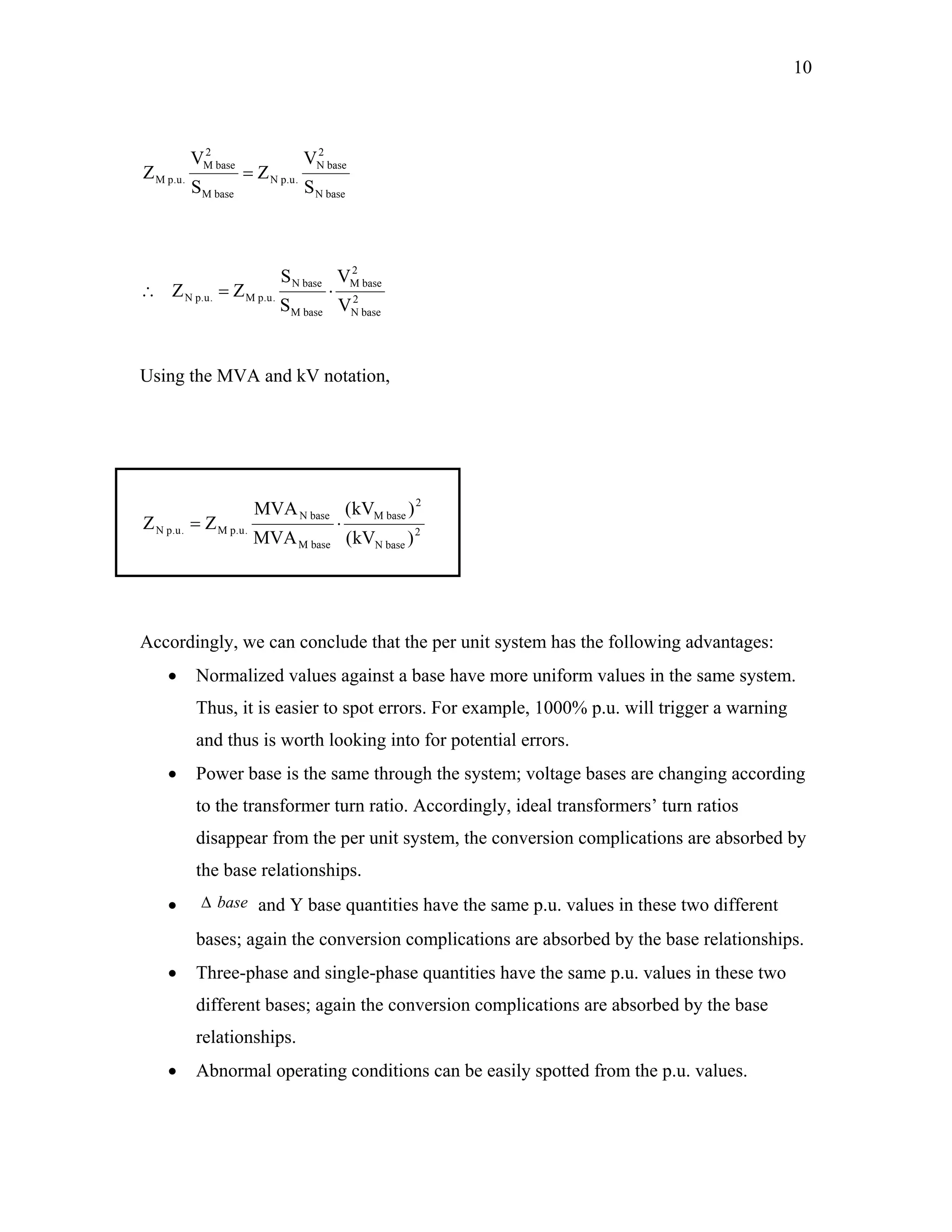
- Per unit calculations absorb complications from differing voltage bases that occur with transformers and other equipment.
- Per unit representations retain phase angle information but present values in a more uniform way that simplifies calculations.
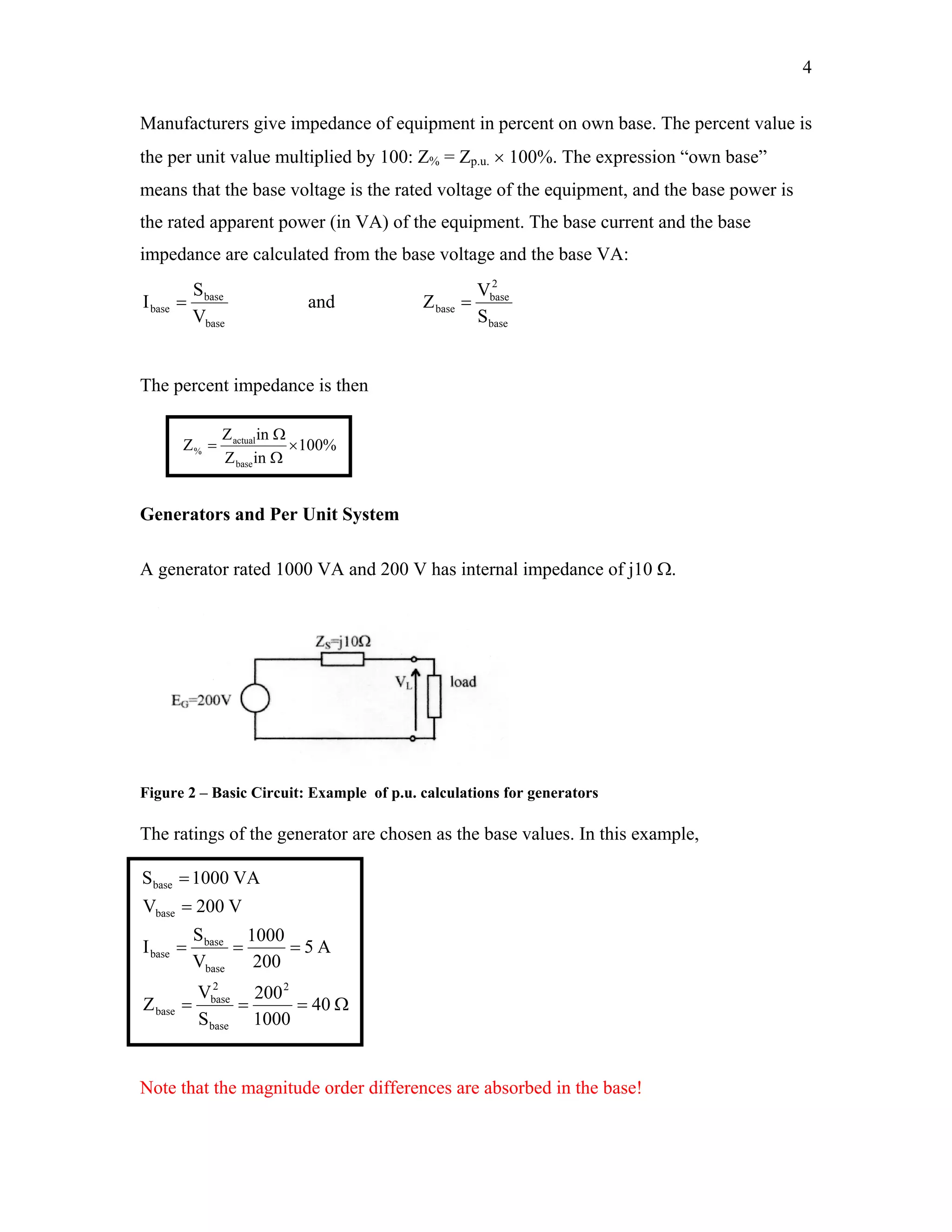
- Generators, transformers and other equipment can be represented by their per unit impedances to
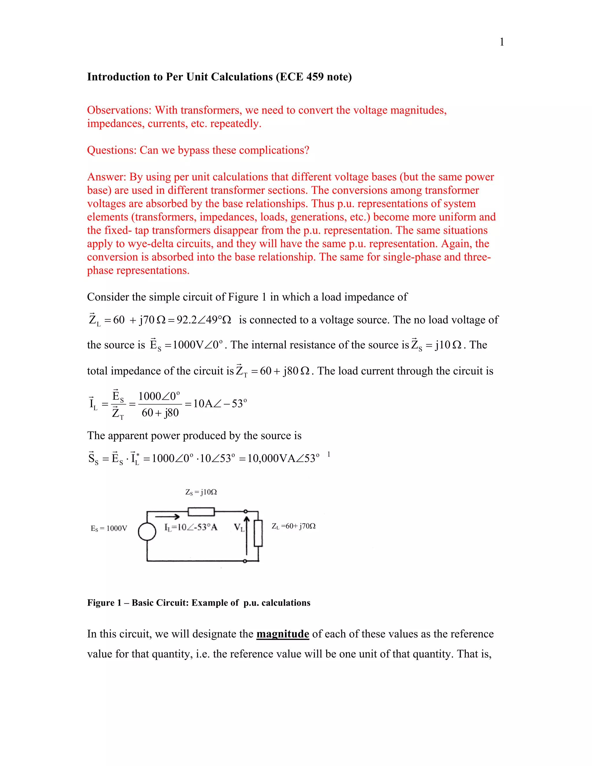
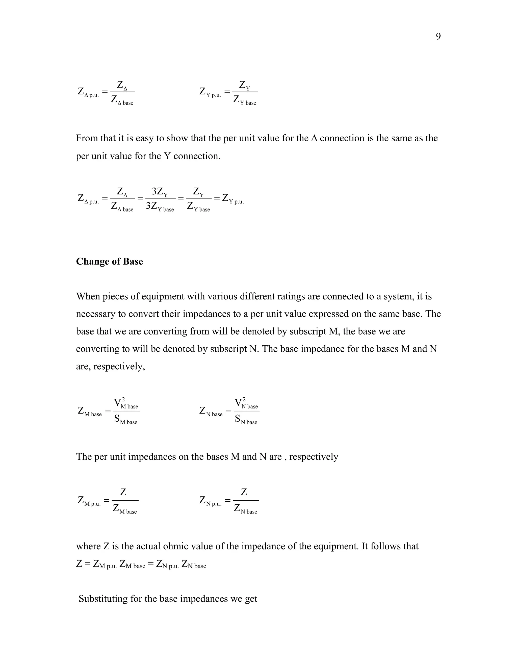


![Eb cvoltages[1]](https://cdn.slidesharecdn.com/ss_thumbnails/ebcvoltages1-140206131744-phpapp02-thumbnail.jpg?width=640&height=640&fit=bounds)


![[LEC-03] Per Unit Calculations (Part-1).pdf](https://cdn.slidesharecdn.com/ss_thumbnails/lec-03perunitcalculationspart-1-241104145204-f700e749-thumbnail.jpg?width=640&height=640&fit=bounds)